STK Professional Audio VM6S-DRVH User manual
VM6S-DRVH, New 400W high power
VM6S-DRVH, 새로운 400와트 고출력
VM 시리즈 포타블 타입 파워드 믹서
사용설명서
VM series Powered Mixer
OWNER'S MANUAL
CD,
10A 5A
270W
1/3 Power

2
VM6S-DRVH, new 400W high power
VM6S-DRVH, 400와트 고출력 파워드 믹서
VM series Powered Mixer
1. Introduction
l
제품 소개
Table of Contents
l
목 차
1. Introduction l 제품 소개.......................................................................................................................................
2-3
2. Important Safety Instructions l 안전을 위한 주의 사항 .................................................................
3-4
3. Important Operating Instructions l 제품 동작시 주의 사항 ........................................................
5-6
4. Warranty Information l 제품 보증에 대해서............................................................................................
7-8
5. Panel Description l 각 부의 명칭 ..................................................................................................................
9-13
6. Connecting Your System l 올바른 연결 방법.......................................................................................
14-15
7. Care and Maintenance l 올바른 제품 관리..............................................................................................
16
8. System Hookup Diagram l 시스템 연결 구성도...................................................................................
17
9. Block Diagram l 회로의 구성도.......................................................................................................................
18
10.
Specications l 제품 규격..................................................................................................................................
19-20
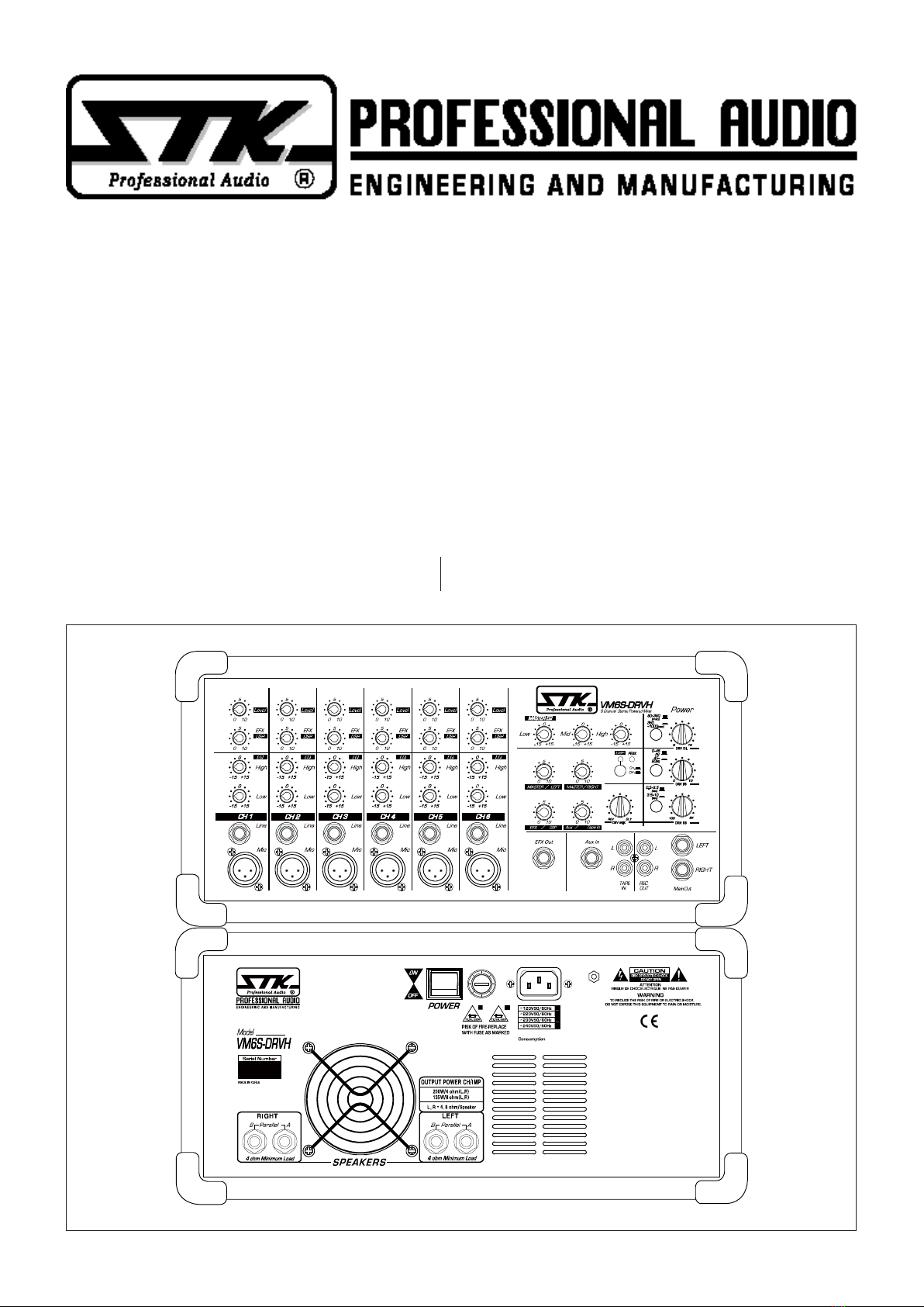
Congratulations and thank you for choosing a STK PROFESSIONAL AUDIO powered mixer.
The new 400W RMS high power VM6S-DRVH power mixer offers solid, feature-packed performance in a compact,
economical format. The VM6S-DRVH features 6 independent channels, each channel incorporates a low impedance,
XLR input and a high impedance quarter inch phone jack inputs.
Separate active high, and low equalization, and STK DRV technology post DSP/effect sends are also provided for
each channel on the VM version. The DRV technology DSP have super maximum time range for ultra clean delay and
reverb effect sounds, also can mixing to maximum ratio(zero to 100%) for reverb and delay level.
VM series Powered Mixer

1. 사용 설명서를 꼭 읽어주세요
제품을 사용하기 전에 본 설명서의 안전과 작동에 관한 모든 기능
설명들을 반드시 읽어 보십시오.
2. 사용 설명서를 잘 보관하세요
안전과 작동에 관한 설명은 나중에 참고하게 될 경우가 있으므로
잘 보관해서 유용하게 사용하십시오.
3. 주의 및 경고사항
사용 설명서에 나타나 있는 모든 주의사항들은 반드시 지켜야 합
니다.
4. 사용법을 지켜주세요
본 설명서의 사용법에 관한 모든 내용들은 반드시 지켜야 합니다.
5. 수분과 습기주의
제품은 물기 또는 습기가 많은 곳에 설치하면 감전의 원인이 됩니
다. (욕조, 세면기, 부엌, 세탁기, 젖은 바닥, 수영장의 풀 근처, 습지
등)
6. 열주의
제품은 전열기구 혹은 열을 발생하는 그 밖의 기구들로부터 떨어
진 곳에 설치되어야 합니다. 설치 전 반드시 주변을 확인하시어 건
조한 장소에 제품을 설치해 주십시오.
3
1. Introduction
l
제품 소개
Ⅱ Important Safety Instructions
l
안전을 위한 주의 사항
1. Read Instructions
All the safety and operating instructions should be read before
the appliance is operated.
2. Retain Instructions
The safety and operating instructions should be retained for
future reference.
3. Heed Warnings
All warnings on this appliance and in the operating
instructions should be adhered to.
4. Follow Instructions
All instructions should be followed.
5. Water and Moisture
This appliance should not be used near water- for example,
near a bathtub, sink, laundry tub, in a wet basement, near a
swimming pool, etc.
6. Heat
This appliance should be situated away from heat sources such
as radiators, heat registers, stoves, or other appliances (including
ampliers) that produce heat.
7. Power Sources
This appliance should be connected to a power supply only
of the type described in the operating instructions or as
STK 프로페셔널 오디오의 파워믹서를 선택해주셔서 감사드립니다. 새로운 400와트 고출력 VM6S-DRVH 믹서는 내
구성이 뛰어나며, 컴팩트하고 경제적인 포맷에 뛰어난 성능을 담은 제품입니다.
VM6S-DRVH는 6개의 독립적인 입력 채널을 특징으로 하며, 각 채널은 XLR입력으로 들어오는 낮은 임피던스와 1/4
인치 폰 잭으로 들어오는 높은 임피던스 입력소스 일체형의 특징을 가지고 있습니다. 새로운 DRVH 버전은 분리된 액
티브 하이, 로우 이퀄리제이션과 STK DRV 기술이 사용된 포스트 DSP/이펙트 샌드가 각 채널마다 제공됩니다. 더불어
STK DRV 프로세서는 깨끗한 음질의 최장 지연 시간의 딜레이와 리버브 음장을 생성하며 디레이와 리버브 음장 믹싱
비율을 제로에서 100%까지 원하는 대로 세팅해줍니다. VM6S-DRVH의 마스터 섹션은 메인 컨트롤을 제공함과 함께,
이펙트/AUX 출력, 그리고 AUX/CD 입력(이펙트 리턴)의 컨트롤을 제공합니다. 또한, 3 밴드의 액티브 이퀄리제이션
기능을 지니고 있습니다. 특히 EQ 섹션에서는 +/-15㏈ 컷/부스트를 실행할 수 있습니다. 새로운 VM6S-DRVH 파워믹
서는 사용이 쉽고 성능이 뛰어나서 단체 모임이나 회합 교육장소 특히 중, 소형 규모의 라이브 뮤직 공연 등에 이상적입
니다. 제품을 사용하시기 전에 본 사용설명서를 꼭 읽고 제품의 특징과 사용방법을 숙지하여 주시기 바랍니다.
The master section provides controls for main L&R, effect/aux send and Aux(effect)/CD inputs. Also the master
section features are three band EQ sections offer +/-15㏈cut and boost capability.
VM 6S-DRVH power mixers ideal for portable PA systems for venues and small medium live sound places. Please
take the time to read this manual before operation so that you fully understand the features and correct use of this ne
products.

marked on the appliance. If you are not sure of the type of
power supply to your home, consult your appliance dealer
or local power company. For appliances intended to operate
from battery power, or other sources, refer to the operating
instructions.
8. Polarization
If the appliance is equipped with a polarized alternating-
current line plug (a plug having one blade wider than the
other), this plug will t into the power outlet only one way.
This is a safety feature. If you are unable to insert the plug
fully into the outlet, try reversing the plug. If the plug should
still fail to t, contact your electrician to replace your obsolete
outlet. Do not defeat the safety purpose of the polarized plug.
9. Grounding
If the appliance is equipped with a 3-wire grounding-type
plug, a plug having a third (grounding) pin, this plug will only
t into a grounding-type power outlet. This is safety feature.
If you are unable to insert the plug into the outlet, contact
your electrician to replace your obsolete outlet. Do not defeat
the safety purpose of the grounding-type plug.
10. Power Cord Protection
Power supply cords should be routed so that they are not
likely to be walked on or pinched by items placed upon or
against them, paying particular attention to cords at plugs,
convenience receptacles, and the point where they exit from
the appliance.
11. Damage Requiring Service
Unplug this appliance from the wall outlet and refer servicing
to qualied service personnel under the following conditions:
a. When the power-supply cord or plug is damaged.
b. If liquid has been spilled, or objects have fallen into the
appliance.
c. If the appliance has been exposed to rain or water.
d. If the appliance does not operate normally by following
the operating Instructions. Adjust only those controls
that are covered by the operating instructions as an
improper adjustment of other controls may result in
damage and will often require extensive work by a
qualied technician to restore the appliance to its normal
operation.
e. If the appliance has been dropped or the cabinet has
been damaged.
f. When the appliance exhibits a distinct change in
performance-this indicates a need for service.
12. Servicing
Do not attempt to service this appliance yourself as opening
or removing covers may expose you to dangerous voltage
or other hazards. Refer all servicing to qualied service
personnel.
7. 전원주의
이 제품은 반드시 사용 설명서에 정해진 타입의 전원 또는 본체에
표시된 전원에 연결되어야 합니다. 만약 사용하려는 전원이 확실
치 않을 때는 전원 기구 판매자나 전원 공급자에게 문의하세요. 공
급되는 전원이 축전지 형태이거나 다른 방식이라면 제품 사용을
피해주세요.
8. 분극 플러그에 대한 주의
만약 전원기구가 극성이 있는 교류전원이라면(플러그 중 한 블레
이드가 다른 것에 비해 넓게 되어 있습니다.) 이 플러그는 오직 한
가지 방법으로 전원 아울렛에 끼워져야 합니다. 이것이 안전한 모
습입니다. 만약 플러그를 올바르게 끼울 수 없다면 플러그를 빼고
다시 시도해 보세요. 만약 그래도 안 된다면 전원 아울렛을 교체하
도록 전기 기사에게 문의하세요. 분극 플러그에 대한 주의사항을
반드시 지켜주세요.
9. 접지 플러그에 대한 주의
만약 전원기구가 3선 접지 타입의 플러그라면 세번째핀(접지핀)을
가지고 있을 것입니다. 이 플러그는 반드시 접지 타입 전원 아울렛
에 맞게 끼워져야 합니다. 이것이 안전한 모습입니다. 만약 이 플
러그를 전원아울렛에 올바르게 끼울 수 없다면 전원 아울렛을 교
체하도록 전기기사에게 문의하세요. 접지 플러그에 대한 주의사항
을 반드시 지켜주세요.
10. 전원 코드의 보호
전원 공급 코드는 플러그, 콘센트, 그리고 본 제품과 연결되는 지
점들에 특별한 주의를 기울이면서 정확한 방향으로 꽂혀야 합니
다. 그렇지 못한 경우에는 화재 및 제품 손상의 원인이 될 수 있습
니다.
11. 제품 손상 수리 서비스
본 제품에 다음과 같은 경우가 발생했을 때, 전문가에 의해서만 수
리를 받을 수 있습니다.
가. 전원공급 코드 혹은 플러그가 손상되었을 경우.
나. 제품 안으로 이 물질이 떨어졌거나 액체가 스며들었을 경우.
다. 제품이 빗물이나 물에 젖었을 경우.
라. 제품이 정상적으로 작동하지 않을 경우 사용설명서에 나와
있는 내용들을 조정해 보세요. 사용 설명서 외의 내용을 조
정할 경우 더 큰 고장의 원인이 될 수 있습니다.
마. 제품이 바닥에 떨어졌을 경우나 본체에 손상이 갔을 경우.
바. 제품이 작동 시 서비스를 필요로 하는 두드러진 변화를 보
일 경우.
12. 서비스
직접 제품을 분해하거나 커버를 벗겨낼 경우 감전 등 여러 위험을
초래할 수 있습니다. 반드시 모든 서비스는 본사의 직원에게 문의
해 주세요.
4
2. Important Safety Instructions
l
안전을 위한 주의 사항

5
3. Important Operating Instructions
l
제품 동작시 주의사항
READ THIS PAGE!!
Please take the time to read this manual before operation so
that you fully understand the features and correct use of this
ne product.
Before control start
1. Turn down the channel LEVEL, EFX/DSP and center the
channel EQ controls.
2. In the output section (right hand side), turn all the rotary
knobs "down," the switches "out".
3. Turn the POWER switch off.
Connections
If you already know how you want to connect the VM-6SDRVH,
go ahead and connect the inputs and outputs the way you
want them. If you just want to get sound through the Power
mixer, follow these steps:
1. Plug in the detachable line cord, connect it to an AC outlet,
and turn ON the POWER switch on the REAR panel.
2. Plug a microphone or other signal source into channel 1's
MIC or LINE input.
3. Hook up speakers to the VM-6SDRVH and turn it on and
master level control to set about 3/4 position.
Set the Levels
To set the channel LEVEL controls, please turn right the level
about one quarter of the way up. The following steps must be
performed one channel at a time.
1. Play something into the selected input. This could be an
instrument, a singing or speaking voice, or a line input
such as a CD player or tape recorder output. Be sure that
the volume of the input source is the same as it would be
during normal use. If it isn't, you might have to readjust
these levels during the middle of the set.
2. Adjust the channel's LEVEL[3] control so that the sounds
on the left/right speaker and stay before distortion of
speaker sound.
3. lf you'd like to apply some EQ, do so now and return to
step 2.
4. Repeat for each channel.
Instant Mixing
1. Leave the microphone plugged into channel 1 and connect
a keyboard, guitar or other instrument to channel 2.
Be sure to "Set the Levels" for channel 2 as described above.
2. To get sound out of the speakers, turn right channel 1 and
2 faders(levels) to the "5" mark, and slowly turn right the
MASTER level control to a comfortable listening level.
3. Sing and play. You're a star! Adjust the faders(levels) for
channel 1 and 2 to bring your voice and your instrument up
and down to create your own mix.
이 페이지를 꼭 읽어주세요!!
제품을 사용하시기 전에 본 사용 설명서를 꼭 읽고 제품의 특징과
사용방법을 숙지하여 주시기를 바랍니다.
시작하기 전에 (전원 케이블을 연결하기 전)
1. 채널 레벨을 최소로 내려주시고, EFX/DSP, 그리고 채널 EQ와
조절기를 중앙에 위치시켜 주십시오.
2. 출력부(제품의 오른쪽)의 모든 로터리-노브(돌리는 조절기)는
“최소”로 낮춰주시고 스위치들은 모두 꺼주십시오.
3. 전원 스위치가 꺼져있는지 확인해 주십시오.
제품의 연결
만약 이미 VM-6SDRVH를 어떻게 연결하는지 알고 계시고 어떤
연결을 원하는지 알고 계시다면 원하는 방법대로 입력부와 출력
부를 연결하시면 됩니다. 하지만 만약 파워 믹서를 통해 음향을 얻
는 방법을 잘 모르신다면 다음의 단계에 따르시면 됩니다.
1. 전원 코드를 연결하십시오. AC 아울렛 단자에 연결하시고, 제
품 전면부에 있는 전원 스위치를 켜주십시오.
2. 채널 1에 있는 마이크 또는 라인 입력부에 마이크나 다른 입력
신호를 연결 하십시오.
3. VM-6SDRVH와 스피커를 연결하고 전원을 켜십시오. 그리고
마스터 레벨 컨트롤을 대략 3/4 위치로 하세요.
레벨 설정하기
채널 레벨 조절은, 먼저 1/4 정도의 위치에 두고 들어보시면 됩니
다. 다음의 단계를 반드시 지켜주시기 바랍니다.
1. 선택한 입력부로 입력신호를 넣으십시오. 이는 악기가 될 수도
있고 노래하거나 연설하는 목소리가 될 수도 있습니다. 또는,
CD 플레이어나 테이프 레코더의 출력등과 같은 음향기기의 라
인 입력이 될 수도 있습니다. 입력 신호원의 출력 볼륨은 일반
적으로 사용하시는 정도로 해 주십시오. 만약 그렇지 않다면,
설정하던 중간에 또다시 레벨을 조절해야 합니다.
2. 채널 레벨[3]을 조절하여 좌, 우 스피커의 사운드를 확인하세
요. 그리고 반드시 사운드가 찌그러짐이 없는 위치에 레벨을 맞
추세요.
3. EQ를 활용하고 싶으시다면, 채널의 고음, 저음 레벨을 원하는
만큼 조절하시고 2번 항을 반복하세요.
4. 위 단계를 각 채널마다 반복하여 해주세요.
인스턴트 믹싱
1. 채널 1에 연결되어 있는 마이크로폰을 그대로 두고 키보드나
기타 또는 다른 악기를 채널 2에 연결하십시오. 채널 2의“레벨
설정하기”역시 위와 같은 방법으로 해주세요.
2. 스피커를 통해 음향을 듣기 위해 채널 1과 2의 레벨 페이더
(볼륨 조절기)를 돌려서“5”의 위치로 놓아 주십시오.
그리고 마스터 레벨 콘트롤을 듣기 좋은 수준으로 조절하여 주
십시오.
3. 노래하고 연주하십시오. 당신은 인기스타입니다! 레벨 콘트롤
을 조절하여 채널 1과 2에 당신의 목소리와 악기 연주 음향을
전달해 자신만의 믹스를 만드세요.

3. Important Operating Instructions
l
제품 동작시 주의사항
Other Nuggets of Wisdom
For optimum sonic performance, channel and MASTER
Control LEVEL should be set near the "5" (unity gain)
markings.
Always turn the MASTER LEVEL knob down before making
connections to and from VM-6SDRVH.
When you shut down your equipment, turn off the VM-6S
DRVH rst. When powering up, turn on the VM-6SDRVH
last.
Never listen to loud music for prolonged periods. Please see
the Safety Instructions on this page for all information on
hearing protection.
Save the shipping box! You may need it someday, and you
don't want to have to pay for another one. That's it for the
after service delivery, moving control room.
After that, you can take the grand tour of the power mixer,
with descriptions of every knob, button input, and output.
We encourage you to take the time to read all of the feature
descriptions, but at least you know it’s there if you have any
questions
추가적인 활용 방법
최적의 음향 성능을 위해 채널과 마스터 레벨 콘트롤은
“5 (유니티 게인)” 근처에 두는 것이 좋습니다.
VM-6SDRVH에 다른 기기를 연결할 때에는 항상 마스터 레벨
노브는 최소로 낮춰 주십시오.
장비의 전원을 끌 때에는 VM-6SDRVH의 전원을 가장 먼저 꺼주
십시오.
전원을 켤 때에는 VM-6SDRVH의 전원을 마지막으로 켜는 것이
좋습니다.
오랜 시간 동안 큰 소리로 음악을 듣는 것은 청각에 매우 위험합니
다.“안전을 위한 주의사항”을 읽고 청각 보호를 위한 안전한 음
악 감상을 하도록 하여 주시길 당부 드립니다.
제품 포장용 박스를 보관해 두시면 좋습니다! 사후 서비스 등을 위
해 제품을 운반할 일이 있을 때 유용합니다. 새것을 원하신다면 구
매하실 수도 있습니다.
자 이제, 파워 믹서로의 투어를 시작하겠습니다. 각각의 모든 노브
의 기능과 입력부, 출력부에 대해 알아보겠습니다. 시간을 들여 믹
서의 모든 특징들을 읽어보기를 권하는 바입니다. 사용 설명서를
모두 읽고 난 후에는 모든 궁금증이 해소되어 있을 것입니다.
6

UNPACKING
As a part of our system of quality control, every STK
product is carefully inspected before leaving the factory
to insure awless appearance.
After unpacking, please inspect for any physical
damage. Save the shipping carton and all packing
materials, as they were carefully designed to reduce the
possibility of transportation damage should the unit
again require packing and shipping.
In the event that damage has occurred, immediately
notify your dealer so that a written claim to cover the
damage can be initiated with the carrier. The right to
any claim against a public carrier can be forfeited if
the carrier is not promptly notied and if the shipping
carton and packing materials are not available for
inspection by the carrier. Save all packing materials until
the claim has been settled.
STK Customer Service Department
396-43, CHEONGCHEON-DONG, BUPYEONG-GU,
INCHEON, KOREA.
TEL : +82-(0)32-525-1788~1790
FAX : +82-(0)32-525-1784
www.stkpro.com
STK LIMITED 1 YEAR WARRANTY
STK electronics are warranted to be free from defects
in materials and workmanship under normal use for a
period of 1 year from date of original purchase.
During that period, STK will at its option, repair
or replace materials at no charge if product has been
delivered to STK by a STK dealer or STK Service Center
together with the original sales receipt or other proof of
purchase.
Warranty excludes fuses, exterior nish, normal wear,
failure due to abuse, or operation outside of specified
ratings. Warranty applies to original purchaser only.
This warranty gives you specic legal rights which vary
from state to state.
For more information about warranty repair,
please contact : Customer Service Dept., The STK
Professional Audio.
FOR YOUR RECORDS
All of us at STK thank you for your expression
of confidence in STK products. The unit you have
purchased is protected by a limited 1 year warranty. To
establish the warranty, be sure to fill out and mail the
warranty card attached to your product.
For you own protection, ll out the information below for you own records.
Other Information :
7
4. Warranty Information
Model Number :
Dealer :
Phone :
Serial Number :
Date Of Purchase :
Salesman :

4. 제품 보증에 대해서
제품 취급에 대해서
본 제품은 우수한 제품 설계과정을 마치고 엄밀한 품
질관리 및 검사과정을 거쳐서 생산된 제품입니다.
제품을 포장에서 꺼낸 후에는, 물리적 충격을 피해주
십시오. 포장상자와 모든 포장 재료들은 제품의 포장과
이동 중에 발생할 수 있는 충격을 완화할 수 있도록 설계
되어 있습니다.
서비스 등 다시 제품을 포장하고 이동해야 할 수 있으
므로 포장상자와 재료들을 보관해 주십시오. 만약 제품
에 충격이 가해졌을 시에는 즉시 판매원에게 알려 빠른
조치가 가능하도록 해주십시오.
운송업자와의 상품 인수 과정에서 손상된 포장용 상자
와 재료들은 운송업자에게 즉시 알리지 않으면 차후에
운송업자에게 불만을 제기할 수 없습니다. 모든 포장용
상자와 포장 용품을 잘 보관해 두시길 바랍니다.
STK 고객 서비스 팀
대한민국 인천 광역시 부평구 청천2동 396-43
TEL : 032-525-1788~1790
FAX : 032-525-1784
E-mail : stkcom@stkpro.com
www.stkpro.com
제품 보증기간은 1년입니다.
STK는 제품을 구입한 날짜로부터 1년 동안 무상으로
AS를 해드립니다. 제품 보증 기간 동안 STK 정식 판매원
이나 STK서비스 센터를 통해 영수증과 함께 본사로 배
달된 제품의 부품의 교환이나 수리는 모두 무료입니다.
퓨즈, 외부흠집 등의 제품의 하자 또는 규격과 다른 내
용 역시 보증내용에 포함됩니다. 보증은 실 구매자에 한
합니다. 이 보증은 국가에 따라 달라질 수 있습니다.
더 자세한 정보를 원하신다면 STK Professional
Audio 고객 서비스 팀에 문의해 주십시오.
FOR YOUR RECORDS
저희 제품을 구매해 주셔서 감사합니다. 구매하신 제
품은 1년간의 무상보증기간을 갖습니다. 보증카드를 작
성하셔서 제품과 함께 보내주시면 확실한 서비스를 받으
실 수 있습니다.
올바른 A/S를 받을 수 있도록 제품을 구입하신 후 아래 사항을 기록하여 보관하여 주시기 바랍니다.
기타 기록사항 :
모델 넘버 :
구입처 :
영업사원 :
시리얼 넘버 :
제품 구매일 :
전화번호 :
8
VM-6SDRVH / VRM-6SDRVH
Note: The operation of the VM6S-DRVH and VRM6S-
DRVH Stereo powered mixer is nearly identical. This manual
will help you understand and get the most out of all VM
series powered mixers.
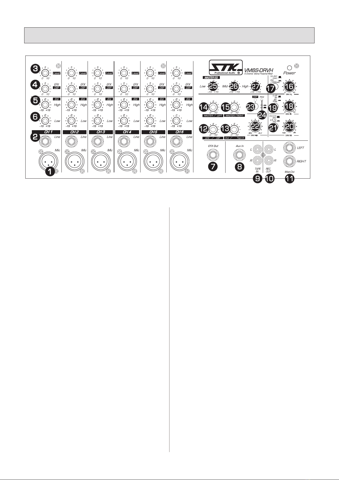
MONO INPUT CHANNELS
1. Mic In
This input accepts a standard XLR microphone connector
and low impedance microphone. Pin 1 is Shield, 2 is Hot and
3 is Cold.
2. Line In
This input accepts a 1/4inch two conductor plug and is
suitable for unbalanced line level sources. Tip is Hot(+),
sleeve is Shield(ground).
3. Level
The channel level control provides continuously variable
adjustment of the channel output level to the main mixing
buss.
4. EFX(DSP)
The channel EFX(DSP) control varies the amount of channel
signal sent to the D.S.P, as well as to the EFX out jack.
5. High
The high frequency shelving control is set at 10kHz. You
can increase or attenuate frequencies 10kHz(and above)up
to 15dB. There is a detente in the 0 position indicating a fat
response.
6. Low
The low frequency shelving control is set at 100Hz. You can
increase or attenuate frequencies 100Hz(and below) up to 15dB.
A detente is provided in the 0 position indicating a at response.
5. Panel Descriptions
l
각 부의 명칭
REV DLY
DRV MIX
50~350
PEAK
45~
90
(%)
350
~1000
(msc)
0~45
(%)
(msc)
0.5~3.5
(sec)
3.5~10
(sec)
010
010
DRV RB
DRV DL
100 8K
DRV FB
VM6S-DRVH
CD,
참고: VM6S-DRVH와 VRM6S-DRVH 스테레오 파워믹서의 동
작 방법은 거의 동일합니다. 이 사용설명서는 VM믹서의 모든 것
을 이해하고 사용하도록 도움을 드릴 것입니다.
모노 입력 채널
1. 마이크 입력
표준형 XLR 마이크로폰 컨넥터(잭)와 낮은 임피던스의 마이크로
폰을 연결하십시오. 핀 1번은 쉴드와 GND, Pin 2번은 핫(플러스)
그리고 핀 3번은 콜드(마이너스) 입니다.
2. 라인 입력
1/4인치 2 컨덕터 잭 플러그와 언밸런스드 라인 레벨 신호에 적합
한 플러그를 연결하십시오. 팁은 핫(플러스) 그리고 링은 쉴드와
GND 입니다.
3. 레벨
채널 볼륨 조절기로 메인 믹싱버스로 가는 채널 출력 레벨을 조절
할 수 있습니다.
4. EFX(DSP)
채널 EFX(DSP) 조절기는 이펙스 샌드 출력 잭으로 보내지는 신호
와 D.S.P로 보내지는 신호의 크기를 조절합니다.
5. 고음역 이퀄라이져
고음역 조절기는 10kHz로 설정되어 있습니다.
10kHz(대역)에서 15dB만큼 올리거나 내릴 수 있습니다.
조절기의 0 위치는 고음역이 평탄한 부분입니다.
6. 저음역 이퀄라이져
저음역 조절기는 100Hz에 설정되어 있습니다. 100Hz(대역)에서
15dB 만큼 올리거나 내릴 수 있으며 그 사이로 조절할 수 있습니
다. 조절기의 0 위치는 저음역이 평탄한 부분입니다.
9

7. EFX 출력
다양한 종류의 외부 이펙트 기기나 모니터 시스템 기기를 연결하
는 잭입니다. 각 채널의 이펙트 조절기로 조정된 신호는 이펙트
버스로 보내지며 EFX OUT 출력 크기가 조절됩니다. 조절된 신호
는 이 잭을 통해 출력됩니다.
8. Aux 입력
외부 이펙트 프로세서나 라인레벨 신호원 출력 잭을 이 잭에 연결
하십시오. 만약 이펙트 프로세서가 모노 출력을 가진 기기라면 모
노 출력은 AUX 입력 잭에 연결하십시오. 이 잭으로 들어오는 신
호들은 L, R버스로 전달됩니다.
9. Tape / CD 입력
RCA 잭 입력은 외부 입력신호를 메인 버스로 보내며 CD나 카세
트, DAT, MD 데크의 스테레오 출력과 연결될 수 있습니다.
10. Rec 출력
마스터 컨트롤을 통과하기 전의 L, R 버스 신호입니다.
11. 메인 L/R 출력
메인 마스터 컨트롤과 3밴드 이퀄라이저를 통과한 스테레오 버스
시그널 출력부입니다.
12. EFX(DSP)
EFX(DSP) 컨트롤로 자체 DSP의 이펙트 사운드 신호의 크기를 제
어할 수 있습니다. 제어된 신호는 L과 R버스로 전달 됩니다.
13. Aux 입력 /Tape 입력 컨트롤
테이프 입력과 AUX 입력으로 들어온 신호를 L과 R 메인 버스로
보내는 크기를 조절합니다.
14. 마스터 L
좌측 메인 출력 컨넥터쪽의 신호 크기를 조절합니다. 그리고, 좌측
내부 앰프의 볼륨 조절기로 사용됩니다.
5. Panel Descriptions
l
각 부의 명칭
7. EFX Out
The input of an external effectors or monitor system can be
connected to this jack. The signal adjusted by the EFFECT
control of each channel will be sent to the EFFECT bus, its
level adjusted of the EFFECT OUT, and output from this
jack.
8. Aux In
Connect these jacks to the output jacks of an external effects
processor or unbalanced line level sources. If the effect
processor has a mono output, can connect it to the AUX IN
jacks. Signal input to these jacks is sent to the L, R bus.
9. Tape /CD In
Use these jacks to connect a stereo device, such as a cassette
player or a CD player. The signal input to these jacks is sent
to the L, R bus.
10. Rec Out
This dual RCA output feeds a recording instrument with a
pre-master level control signal.
11. Main L/R Out
The Stereo bus signal which has passed through the main
MASTER Left/Right control and 3 band equalizer.
12. EFX(DSP)
The overall control effect sound level from the internal D.S.P.
the EFX levels of channel signal sent to the D.S.P, as well as
to the effects send circuitry.
13. Aux In /Tape In Control
This control varies the amount of the signal from the Tape or
'CD In' and 'Aux In' mixed back to the main bus.
14. Master Left
This control provides adjustment of signal to the left main
output connector, and serves as a volume control for the left
internal amplier.
REV DLY
DRV MIX
50~350
PEAK
45~
90
(%)
350
~1000
(msc)
0~45
(%)
(msc)
0.5~3.5
(sec)
3.5~10
(sec)
010
010
DRV RB
DRV DL
100 8K
DRV FB
VM6S-DRVH
CD,
10

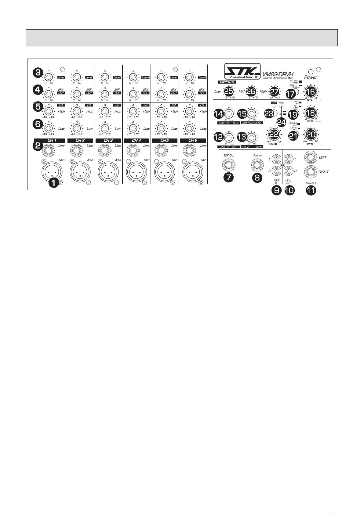
15. Master Right
This control provides adjustment of signal to the Right main
output connector, and serves as a volume control for the right
internal amplier.
16. Delay Time Adjust
This control adjusts the length of time between each delay
repetition.
17. Delay Time Range Select
This push control select delay time range from "50~350(msec)"
to "350~1000(msec)".
18. Delay Feedback Adjust
This control adjusts the number of repetition in the delay effect.
19. Delay Feedback Range Select
This push control select delay feedback range from
"0~45(%)" to "45~90(%)".
20. Reverb Time Adjust
This control adjusts the length of reverb time between each
reverbration.
21. Reverb Time Range Select
This push control select reverb time range from 0.5~3.5(sec)
or 3.5~10(sec).
22. Reverb and Delay Mix Balance Adjust
This control adjust mixing ratio the reverb effect level and
delay effect level to the main L/R bus.
23. DSP Switch/On Indicator
This push control activates/deactivates the DSP effects and LED.
24. DSP Peak Indicator
The purpose of the red PEAK LED is to indicate when
digital effect input signal is dangerously close to clipping.
Digital Signal Processor Function and Features
The STK digital effect processors gives the power to
create original sounds with a wide range of effects. Effect
patch(effect setting) can be stored in the internal memory,
calling up any patch is quick and easy by linear potentiometer.
FEATURES
* Stereo-Effect preset available divided by potentiometer.
* Easy program selection methods.
* Automatic input audio signal "overshooting" indication
circuit on-board.
* Usage of a 1M byte SRAM for superior quality stereo
reverb and delay sound.
* Usage of the famous ASAHIKASEI 24bit DSP with built
in 20 bit AD/DA stereo converter.
* 20bit delta sigma 64 x oversampling AD converter.
* 20bit delta sigma 128 x oversampling AD converter.
* 64 x oversampling ADC digital lter.
* 128 x oversampling DAC digital lter.
* CD-quality professional sound reality.
15. 마스터 R
좌측 메인 출력 컨넥터쪽의 신호 크기를 조절합니다. 그리고, 우측
내부 앰프의 볼륨 조절기로 사용됩니다.
16. 딜레이 타임 조절기
딜레이 효과음 지연 시간을 조절합니다.
17. 딜레이 타임 범위 선택
스위치를 누르면 딜레이 타임 범위를 "50~350(msec)"에서
"350~1000(msec)"까지 선택 할 수 있습니다.
18. 딜레이 피드백 조절기
딜레이 효과음의 반복 시간을 조절합니다.
19. 딜레이 피드백 범위 선택
스위치를 누르면 딜레이 피드백 범위를 "0~45(%)"에서
"45~90(%)"까지 선택 할 수 있습니다.
20. 리버브 타임 조절기
리버브 효과음 잔향 지연 시간을 조절합니다. .
21. 리버브 타임 범위 선택
스위치를 누르면 리버브 타임 범위를 "0.5~3.5(sec)"에서
"3.5~10(sec)"까지 선택 할 수 있습니다.
22. 리버브와 딜레이 믹스 밸런스 조절기
리버브 또는 딜레이 효과음의 상호 믹싱 비율을 조절하여 L과 R
메인 버스로 보냅니다.
23. DSP 스위치와 동작 표시등
DSP 이펙트를 활성화/비활성화 하는 스위치 동작 상태를 알려줍
니다.
24. DSP 피크 표시등
디지털 이팩트 입력 신호가 클리핑에 가까워져 사운드가 나빠지
면 피크 등이 켜집니다.
디지털 시그널 프로세서의 기능과 특징
STK 디지털 리버브는 넓은 범위의 이펙트와 함께 오리지널 사운
드를 창조할 수 있는 힘을 제공합니다.
이펙트 패치(이펙트 설정)는 내부 메모리에 저장될 수 있으며, 패
치를 로딩 하는 것은 리니어 전위차계에 의해 쉽고 빠르게 할 수
있습니다.
특징
* 전위차계(포텐시오메타)로 나뉜 스테레오-이펙트 선(미리) 설치
가능.
* 쉬운 프로그램 선택 방법.
* 입력 오디오 신호 "오버슈팅" 자동 알림 회로.
* 고품질 스테레오 잔향과 지연 사운드를 위한 1M 바이트 SRAM
사용.
* 내장형 20 비트 AD/DA 스테레오 컨버터와
유명한 ASAHIKASEI 24비트 DSP 사용.
* 20비트 델타 시그마 64 x 오버 샘플링 AD 컨버터.
* 20비트 델타 시그마 128 x 오버 샘플링 AD 컨버터.
* 64 x 오버샘플링 ADC 디지털 필터.
* 128 x 오버샘플링 ADC 디지털 필터.
* 리얼리티가 뛰어난 프로페셔널 CD 음향.
5. Panel Descriptions
l
각 부의 명칭
11
어플리케이션
* 긴 시간의 지연과 이슬람 사원 용도급의 반복 능력.
* 환상적인 아시아형 가라오케 사운드 시스템.
* 깨끗하고 밝은 에코 피드백과 유럽형 가라오케
보컬 사운드에 맞춘 딜레이.
* 키보드, 기타 그리고 콤보.
25. 저역 채널 이퀄리제이션 컨트롤
저역 EQ 조절기는 연속적으로 다양하게 활성화되는 쉘빙 이퀄리
제이션에서 100Hz에서 +/-15dB로 이득을 조절하여 L과 R 출력으
로 보내집니다.
26. 중역 채널 이퀄리제이션 컨트롤
중역 EQ 조절기는 연속적으로 다양하게 활성화되는 피킹 이퀄리
제이션에서 2.5kHz에서 +/-15dB로 이득을 조절하여 L과 R 출력
으로 보냅니다.
27. 고역 채널 이퀄리제이션 컨트롤
고역 EQ 조절기는 연속적으로 다양하게 활성화되는 쉘빙 이퀄리
제이션에서 10kHz에서 +/-15dB로 이득을 조절하여 L과 R 출력으
로 보냅니다.
5. Panel Descriptions
l
각 부의 명칭
REV DLY
DRV MIX
50~350
PEAK
45~
90
(%)
350
~1000
(msc)
0~45
(%)
(msc)
0.5~3.5
(sec)
3.5~10
(sec)
010
010
DRV RB
DRV DL
100 8K
DRV FB
VM6S-DRVH
CD,
APPLICATIONS
* Long time delay and repeat for moslem church.
* Fantastic Karaoke sound system for Asian.
* Very clean and bright echo feedback and delay for european
karaoke vocal sound.
* Keyboard, guitar and combos.
25. Low Frequency Equalization Control
The low EQ control alters the low frequency response of the
combined overall signal of the main L.R bus providing
+/-15dB at 100Hz of continuously variable active shelving
equalization.
26. Mid Frequency Equalization Control
The Mid EQ control alters the mid frequency response of the
combined overall signal of the main L.R bus providing
+/-15dB at 2.5kHz of continuously variable active peaking
equalization.
27. High Frequency Equalization Control
The High EQ control alters the high frequency response of
the combined overall signal of the main L.R bus providing
+/-15dB at 10kHz of continuously variable active shelving
equalization.
12

1. 전원 스위치
AC메인 파워를 제품에 공급하는 스위치입니다. 스위치가 위쪽(on
위치)이면 전원이 들어가며 전원 표시등이 켜지게 됩니다.
2. 퓨즈
퓨즈는 퓨즈 홀더에 위치해 있습니다. (섹션 10 제품 규격을 참고
하세요.)
3. IEC 소켓
VM 시리즈 파워드 믹서에 AC 전원을 공급하기 위해 AC 전원 코
드를 연결하는 부분입니다. 각 모델에 맞는 전원 선을 소켓에 끼워
주세요.
4. 오른쪽 출력
2개의 병렬 스피커 출력 잭에 표준형 1/4"2-컨덕터 폰 플러그를
끼우십시오. 4옴에서 출력 200와트를 제공하며 8옴에서 135와트의
출력을 공급합니다. 4옴 이하의 로드 임피던스는 추가적인 파워를
끌어오지 않을 것이며 기기를 보호(PRT) 모드로 전환 시킬 것입니
다.
5. 왼쪽 출력
2개의 병렬 스피커 출력 잭에 표준형 1/4"2-컨덕터 폰 플러그를
끼우십시오. 4옴에서 출력 200와트를 제공하며 8옴에서 135와트의
출력을 공급합니다. 4옴 이하의 로드 임피던스는 추가적인 파워를
끌어오지 않을 것이며 기기를 보호(PRT) 모드로 전환 시킬 것입니
다.
1. Power Switch
This switch controls the AC mains power to your powered
mixer. Power is on when the switch is in the on(up)
position and is conrmed when the power LED indicator is
illuminated.
2. FUSE
The fuse is located in the fuse holder.
(See Section Ⅷ Specications for the correct values.)
3. IEC Socket
This is where you connect the supplied AC line cord to
provide AC power to the all VM series powered mixer. Plug
the line cord into an AC socket properly congured for your
particular model.
4. Right Out
These two parallel speaker output jacks accept standard 1/4
"
two-conductor phone plugs, providing 200 watts of power at
4 ohms, or 135watts at 8 ohms.
Load impedances less than 4 ohms will not draw additional
power and may cause the unit to go into protect mode.
5. Left Out
These two parallel speaker output jacks accept standard 1/4
"
two-conductor phone plugs, providing 200 watts of power at
4 ohms, or 135watts at 8 ohms.
Load impedances less than 4 ohms will not draw additional
power and may cause the unit to go into protect mode.
5. Panel Descriptions
l
각 부의 명칭
321
2
135
REAR PANEL l 후면부
13

6. Connecting Your System
l
올바른 설치 방법
A. 컨넥터
본 제품은 여러 개의 입, 출력 컨넥터(잭)를 사용합니다.
1. XLR 입력 잭
전기적 밸런스드 입력부에 표준형 XLR 돌출형 컨넥터(잭)를 끼웁
니다.
핀1=ground, 핀2=hot 또는 positive(+)
핀3=cold 또는 negative (-). (그림 1 참고)
이 컨넥터(잭)들은 낮은 임피던스의 마이크로폰에 활용됩니다. 높
은 임피던스의 마이크로 폰을 사용하신다면, 1/4"컨넥터(잭)가
장착된 코드를 사용하시는 것이 좋습니다.
이 경우, 마이크로폰을 라인 입력으로 끼워 충당하는 것이 되며 성
능과 음량은 최대 성능에 못 미치게 줄어들게 됩니다. 고품질의 낮
은 임피던스를 가진 마이크를 사용하시길 권하는 바입니다.
2. 1/4″폰 입력 잭
tip/sleeve 잭에 일반적인 돌출형 폰 플러그를 사용하는 언밸런스
드 라인 레벨 시그널을 끼워 주세요. (그림 2 참고)
3. 스피커 출력 잭
스피커 출력 잭은 1/4″2 컨덕터 잭입니다.
파워 출력과 기능은 사용하는 특정 잭이나 와이어에 따라 달라집
니다. (그림 3 참고)
4. RCA 폰 잭
RCA 잭에 언밸런스드 돌출형 핀 컨넥터(잭)를 끼워 주세요.
(그림 4 참고)
A. CONNECTORS
Your powered mixers uses several types of input and output
connectors.
1. XLR Input jacks
Electronically balanced inputs accept a standard XLR
male connector. Pin1=ground, pin2=hot or positive(+) and
pin3=cold or negative (-) (see Figure 1).
These connectors should be utilized for low impedance
microphones. If you are using a high impedances microphone,
it will likely have a cord with a 1/4
"connector on it. In this
case, it would be appropriate to plug such microphones into a
line input, however performance, and gain may be lessened.
for best performance. We recommend you invest in one of
the many higher quality, law impedance mics available on the
market, or alternatively, purchase an impedance matching
transformer from your dealer.
2. 1/4″Phone Input Jacks
These tip / sleeve jacks accept an unbalanced line level signal
using a normal male phone plug. (See Figure 2)
3. Speaker Output Jacks
The speaker output jacks are 1/4″two conductor jacks. Their
power output and function are dependent upon the particular
unit that you are using. (See Figure 3)
4. RCA Phone Jacks
The RCA jacks accept unbalanced male pin connectors.
(See Figure 4)
Figure 1. Female Three Pin Connector Figure 2. Unbalanced 1/4'' Connector
Figure 4. RCA JACKFigure 3. SPEAKER JACKS
1. GROUND
(shield)
2. HOT +
3. COLD -
1 2
3
POSITIVE(+)
GROUND(shield)
POSITIVE(+)
NEGATIVE(-)
14

6. Connecting Your System
l
올바른 설치 방법
B. BASIC OPERATION MODES
Before you begin your connections, you must decide how you
will congure your sound system, 4 ohm or 8 ohm. Below are
system variations that can be used with your powered mixer.
Carefully consider all of them to decide which system you
will use.
NOTE : The VM Mixers feature exible patching options
which make possible more variations of setup than are
presented here. Once familiarized with the unit's capabilities,
you should be able to achieve practically any setup you desire.
1. Powered Stereo 8 ohm
The basic stereo setup: One or more input devices such as a
microphone, keyboard, CD player, or tape deck: An optional
external effects processor:
2 of 8 ohm speaker systems connected to each of the left and
right sides of the output.
2. Power Stereo 4 ohm
The basic stereo setup : One or more input devices such as a
microphone, keyboard, CD player, or tape deck: An optional
external effects processor :
2 of 8 ohm parallel speaker systems connected to the left
output and 2 of 8 ohm parallel speaker systems connected to
right output.
3.Connect the speakers
When connecting your speakers using 1/4" jack method,
be sure to pay close attention to proper polarity. Although
connecting your speaker systems out of phase using the wrong
polarity will not damage your speakers, it will affect the
quality of sound. When using bare wire connections, be sure
that your connections are "clean". If any strands of wire from
one connector are allowed to touch the adjacent connector,
damage to your amplier and sound system could occur.
WARNING: Operating your VM powered mixer at an
output impedance less than 4 ohms/side can damage your
unit and void your warranty!
B. 기본 동작 모드
시스템 연결에 앞서, 시스템 구성을 4옴 혹은 8옴 중 무엇으로 할
지 결정해야 합니다. 다음의 예들은 본 제품으로 가능한 연결들을
보여주고 있습니다. 사용하는 목적에 맞게 사용하려는 시스템 구
성을 선택해 주세요.
참고 : VM 믹서는 본 사용 설명서에 나와 있는 연결들 외에
도 다양한 구성이 가능한 유연한 패치 옵션을 특징으로 합니
다. 기기에 익숙해지면, 다양한 시스템 구성을 원하시는 대
로 하실 수 있습니다.
1. 파워드 스테레오 8옴
기본 스테레오 설치입니다: 마이크로폰, 키보드, CD 플레이어 테
이프 데크 등의 외부 입력기기, 추가적인 외부 이펙트 프로세서,
스테레오로 동작하는 좌, 우 출력부에 각각 연결된 하나씩의 8옴
스피커, 추가적인 외부 파워드 모니터 시스템으로 구성되어 있습
니다.
2. 파워드 스테레오 4 옴
기본 스테레오 설치입니다 : 마이크로폰, 키보드, CD 플레이어 테
이프 데크 등의 외부 입력기기, 추가적인 외부 이펙트 프로세서,
스테레오로 동작하는 좌, 우 출력부에 각각 병렬 연결된 2조씩의 8
옴 스피커, 추가적인 외부 파워드 모니터 시스템으로 구성되어 있
습니다.
3. 스피커 연결
스피커 연결은 표준 규격에 맞는 1/4인치 잭 컨넥터를 사용할 수
있습니다. 연결이 잘 되어 있다면 안전하고 확실하게 높은 파워의
신호를 전달합니다. 가능한 모든 사고를 예방하기 위해서 연결이
확실히 이뤄지기 전에는 절대 전원을 연결하지 마십시오. 또한, 어
떤 방식의 연결을 선택하셨던 간에 올바르게 극성을 연결하도록
주의를 기울이십시오. 극성을 잘못 연결했음에도 불구하고 스피커
에 손상을 입히지 않는다면 반드시 음질에 문제가 생길 것입니다.
베어 와이어(연심투명선)를 사용하여 연결할 경우 간단하고 깔끔
하게 연결이 잘 되었는지 확인해야 합니다. 만약 한 가닥이라도 접
속단자에 인접하여 단자를 건드리게 된다면 앰프에 손상을 입힐
것이며 다른 사운드 시스템에도 손상을 입히게 됩니다.
주의: 4 옴 이하에서 VM 파워드 믹서를 동작시 킬 경우 기기에 손
상을 입힐 수 있으며 이는 보증 대상에서 제외됩니다.
15

Your VM Mixer is built to provide years of dependable
service under demanding circumstances. It requires no
internal maintenance but a common sense approach to
its use will help you enjoy long and reliable operation.
Here are some tips:
1. Power Requirements
Your powered mixer is capable of 110-120V AC or 220-240V
AC operation allowing world-wide usage.
It is pre-wired at the factory for the correct voltage in your
country. It is possible to change the mains voltage but it is an
internal operation that can only be performed by an
experienced technician.
Contact your dealer or service center for more information.
2. Periodic Cleaning
Keep the unit clean by wiping frequently with a damp, soft
cloth. Use a mild detergent cleaner if necessary, Applied to
the cloth, but not directly to the mixer. Do not use solvents
or the other chemicals to clean the unit. A large(dry) paint
brush is useful to remove cumulated dust from between the
many control knobs on the mixer.
If you accidentally spill liquid onto or into the unit,
disconnect the power cord and allow the unit to dry
thoroughly before attempting to use it.
3. Connecting Cables
Use only high quality connecting cables with your VM mixer.
Faulty or suspicious cables should be replaced to avoid
possible deterioration of your sound quality.
4. Connections
Check cable connections frequently, if you move your
equipment often, check input and output jack condition to
be sure they have not sustained any transportation damage,
in temporary installations, such as live performances,
check all cable connections before each performance In
permanent installations, verify the operation of all cables and
connections often. It is much easier to dead with a poor cable
or connection before a performance or recording session
than during it.
VM 믹서는 수요환경에 따라 신뢰할 만한 성능과 서비스로 수년간
제공되어온 고품질 파워 믹서입니다. 내부적으로 추가적인 유지방
법이 필요한 것은 아니지만, 일반 상식적인 방법으로 제품의 수명
을 길게 하고 신뢰할 만한 동작을 유지할 수 있습니다.
다음을 참고하십시오.
1. 요구 전력
본 파워드 믹서는 110-120V AC 나 220-240V AC에서 동작하도록
설계되었습니다. 이는 제조 라인 생산시 미리 결정되어 고정된 것
입니다. 메인 전압을 바꾸는 것은 가능하지만 내부 동작의 변경은
오직 관련 기술자만이 할 수 있습니다.
더 자세한 정보를 원하시면 판매자나 서비스 센터에 문의해 주십
시오.
2. 주기적으로 청소해 주세요.
주기적으로 마른 걸레나 부드러운 천을 이용해 기기를 닦아 주십
시오. 필요하시다면 약한 성분의 세제를 천에 묻혀서 사용 하셔도
좋습니다. 그러나 기기에 세제를 직접 사용하지는 마세요. 솔벤트
나 기타 화학 약품을 사용 하셔서는 안됩니다. 큰 페이트 붓(마른
것)을 사용해 각 조절기들 사이의 먼지를 털어내는 것도 좋습니다.
기기에 액체를 쏟았을 경우에는 전원 코드의 연결을 해제하시고
기기가 마를 때까지 기다린 후에 사용 하십시오.
3. 케이블 연결
VM 믹서 에는 좋은 품질의 연결 케이블을 사용해 주세요. 케이블
을 잘못 연결하거나 좋지 않은 품질의 불량 케이블을 사용 하실 경
우 음질에 문제가 생길 수 있습니다.
4. 기기의 연결
자주 기기를 옮기신다면 케이블 체크를 자주 해 주십시오. 입출력
잭을 자주 확인 하시고 이동 중 생길 수 있는 손상은 없는지 체크
해 주십시오. 라이브 공연 등과 같이 일시적으로 설치하실 때에는
공연 시작 전에 반드시 모든 케이블 연결을 잘 확인 해 주십시오.
또한 모든 케이블의 기능을 잘 구분해 놓으시면 연결 오류로 인해
생기는 문제를 빠르게 조치하실 수 있습니다.
7. Care and Maintenance
l
올바른 제품 관리
16
Ⅰ Introduction
l
제품 소개
8. System Hookup Diagram
l
시스템 연결 구성도
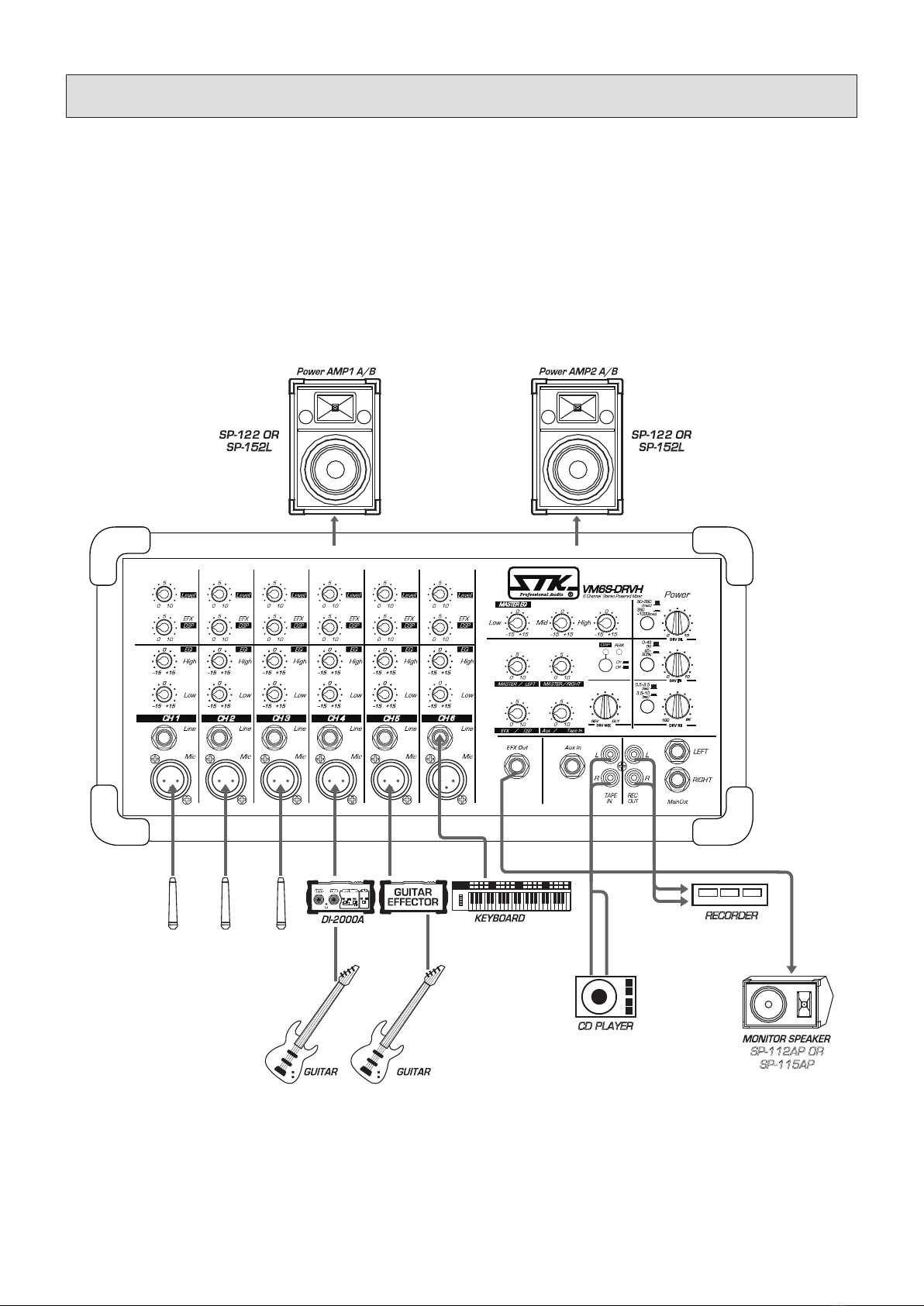
As a band with VM6S-DRVH l VM6S-DRVH 라이브 연주
VM6S-DRVH 라이브 연출 시스템에 적합하게 사용한 예입니다.
Here is an example of using the VM6S-DRVH as a compact system for a band.
DRV MIX
50~350
PEAK
45~
90
(%)
350
~1000
(msc)
0~45
(%)
(msc)
0.5~3.5
(sec)
3.5~10
(sec)
010
010
DRV RB
DRV DL
REV DLY
100 8K
DRV FB
VM6S-DRVH
CD,
RECORDER
152L 152L
CD PLAYER
SP-112AP OR
SP-115AP
17

Ⅰ Introduction
l
제품 소개
9. Block Diagram
l
회로의 구성도
18

10. Specications
l
제품 규격
(1) Sensitivity is the lowest level that will produce a full power output, or the nominal output level when
the unit is set to maximum gain.
(2) XLR connectors are balanced. Phone jacks are unbalanced.
(3) Specications subject to change without notice.
NOTES :
MODEL VM6S-DRVH
Power Output Level(EIA)
l
최대출력
RL 4Ω
RL 8Ω
2 x 180W (THD 0.1%) / 2 x 220W (THD 1%)
2 x 130W (THD 0.1%) / 2 x 145W (THD 1%)
Total Harmonic Distortion
l
왜율
f=1㎑, Rated output RL 4Ω
Rated output RL 8Ω
Main output +4㏈m/600Ω
0.05%
0.05%
0.08%
Frequency Response
l
주파수 응답
20㎐~20㎑, 8Ω, 1 watt
CH In to Main Out @+4㏈m
+1, -2㏈
+1, -2㏈
Hum and Noise
l
전원 및 내부 노이즈
20㎐~20㎑, Rs=1500Ω
-110㏈ Equivalent input noise
-70㏈ Residual output noise (SP OUT)
-97㏈ Residual output noise (MAIN OUT)
Cross Talk
l
크로스 토크
60㏈ at 1㎑, adjacent channel inputs.
60㏈ at 1㎑, Input to Output.
Equalization
l
채널 이퀄리제이션
± 15㏈ shelving
± 15㏈ shelving
High : 10kHz
Low : 100Hz
Master Equalization
l
마스터 이퀄리제이션
±15㏈ maximum boost or cut in each of three bands.
High : 10kHz shelving ±15dB
Mid : 2.5kHz peaking ±15dB
Low : 100Hz shelving ±15dB
Protection circuit
l
보호 회로
Short circuit current limit
DC protection at speaker output
Power ON/OFF transient
AC line fuse
Indicators
l
표시등 Power(Green)
DC offset voltage
l
파워 출력 중점 직류 전압 ≥DC10 ㎷
Dimension (W×D×H)
l
외형치수 390×241×198 mm
Weight
l
제품 무게 (포장포함/제품) 8.96 ㎏ / 8.58 ㎏
Power Consumption
l
소비전력
300W
FUSE 120V...............10A
220V~240V....T5A
Connector
l
사용 커넥터
Bal XLR input
Unbal 1/4" input
Unbal 1/4" output
(1) 감도는 가장 낮은 레벨로 풀 파워 출력을 내거나 유닛이 최대 게인으로 설정된 상태의 명목 출력 레벨을 뜻합니다.
(2) XLR 컨넥터는 밸런스드입니다. 폰잭은 언밸런스드입니다.
(3) 제품 사양은 제품의 품질과 성능 향상을 위해 예고 없이 바뀔 수 있습니다.
참고 :
19
10. Specications
l
제품 규격
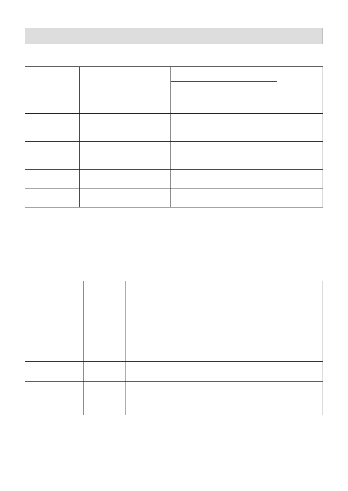
Input specications l 입력부 규격
Output specications l 출력부 규격
(1) Sensitivity is the lowest level that will produce a full power output, or the nominal output level when the unit is set to maximum
gain.
(2) XLR connectors are balanced. Phone jacks are unbalanced.
(1) All connectors are unbalanced.
(2) In these specications, when dB represents a specic voltage, 0 dB is referenced to 0.775 Vrms.
NOTES :
NOTES :
Input terminals
l
입력 터미널
Actual Load
Impedance
l
내부 순저항
For use
with nominal
l
외부 접속 저항
Input level
l
입력레벨
Connector
in mixer
l
사용 커넥터
Sensitivity
l
감도
Nominal(limit)
l
표준
Max. before
clip (main out)
l
최대
MIC IN
l
마이크 입력
LOW IMPEDANCE 4 kohms 600
ohms mic
-50 dBu
(2.45 mV) ±1 dB -34 dBu
(15.5 mV) XLR Jack
LINE IN
l
라인입력
LINE IMPEDANCE 4 kohms 600
ohms lines
-20 dBu
(77.5 mV) ±1 dB -14 dBu
(154 mV) Phone Jack
AUX IN
l
억스입력 10 kohms 600
ohms lines
-10 dBu
(245.0 mV) ±1 dB 6 dBu
(1.5 mV) Phone Jack
TAPE IN
l
테이프 입력 10 kohms 600
ohms lines
-10 dBu
(245.0 mV) ±1 dB 6 dB
(1.5 mV) RCA Jack
(1) 감도는 가장 낮은 레벨로 풀 파워 출력을 내거나 유닛이 최대 게인으로 설정된 상태의 명목 출력 레벨을 뜻합니다.
(2) XLR 컨넥터는 밸런스드입니다. 폰잭은 언밸런스드입니다.
1) 모든 컨넥터는 언밸런스드입니다.
2) 본 사양에서 dB는 특정 전압을 나타냅니다. 0dB는 0.775Vrms입니다.
참고 :
참고 :
Output terminals
l
출력 터미널
Actual Load
Impedance
l
내부 순저항
For use with
nominal
l
외부 접속 저항
Onput level
l
출력레벨 Connector in mixer
l
사용 커넥터
Nominal
l
표준
Max. before clip
l
최대 가용 출력
SPEAKER OUT
l
스피커 출력 0.08 ohm
4 ohms SP 180W X 2 200W X 2 Phone Jack
8 ohms SP 120W X 2 135W X 2 Phone Jack
MAIN L, R OUT
l
메인 L, R 출력 600 ohm 10k ohms lines +4dBu
(1.2 V)
+20 dBu
(8.3 V) Phone Jack
EFX SEND
l
이팩트 샌드 출력 600 ohm 10k ohms lines +4dBu
(1.2 V)
+20 dBu
(8.3 V) Phone Jack
TAPE OUT
l
테이프 출력 600 ohm 10k ohms lines -10dBu
(245 mV)
+12 dBu
(3.07 V) RCA Jack
20
Table of contents
Other STK Professional Audio Music Mixer manuals

STK Professional Audio
STK Professional Audio VX-804FX User manual

STK Professional Audio
STK Professional Audio VX1443-FDR User manual

STK Professional Audio
STK Professional Audio SM-16S DDR PowerPlus User manual

STK Professional Audio
STK Professional Audio VM 6 User manual

STK Professional Audio
STK Professional Audio VM11T-DRV User manual

STK Professional Audio
STK Professional Audio VX-804FXH User manual

STK Professional Audio
STK Professional Audio VX-2442 User manual

STK Professional Audio
STK Professional Audio VM-11T DRV User manual

STK Professional Audio
STK Professional Audio SM-16SDDR User manual

STK Professional Audio
STK Professional Audio VX1443-FDR User manual


