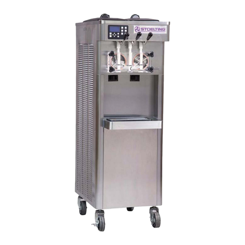
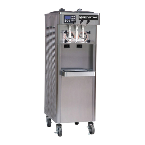
Stoelting CC Series User manual

Model CC101, CC202, CC303, CC404
OWNERS MANUAL
Manual No. 513642 Rev.2


This manual provides basic information about the machine. Instructions and suggestions are
given covering its operation and care.
The illustrations and specifications are not binding in detail. We reserve the right to make
changes to the machine without notice, and without incurring any obligation to modify or pro-
vide new parts for machines built prior to date of change.
DO NOTATTEMPT to operate the machine until instructions and safety precautions in this
manual are read completely and are thoroughly understood. If problems develop or questions
arise in connection with installation, operation, or servicing of the machine, contact the com-
pany at the following location:
STOELTING Ph: 800-558-5807
502 Hwy. 67
Kiel, WI 53042 Fax: 920-894-7029
© 2012 Stoelting, LLC, All Rights Reserved
Owner’s Manual
For CC Series
Continuous Flow Machines

Safety Alert Symbol:
This symbol Indicates danger, warning or caution.
Attention is required in order to avoid serious per-
sonal injury. The message that follows the symbol
contains important information about safety.
Signal Word:
Signal words are distinctive words used throughout
this manual that alert the reader to the existence and
relative degree of a hazard.
CAUTION
The signal word “CAUTION” indicates a potentially
hazardous situation, which, if not avoided, may result
in minor or moderate injury and equipment/property
damage.
A Few Words About Safety
Safety Information
Read and understand the entire manual before
operating or maintaining Stoelting equipment.
This manual provides the operator with information
for the safe operation and maintenance of Stoelting
equipment. As with any machine, there are hazards
associated with their operation. For this reason safety
is emphasized throughout the manual. To highlight
specific safety information, the following safety defini-
tions are provided to assist the reader.
The purpose of safety symbols is to attract your at-
tention to possible dangers. The safety symbols, and
their explanations, deserve your careful attention
and understanding. The safety warnings do not by
themselves eliminate any danger. The instructions
or warnings they give are not substitutes for proper
accident prevention measures.
If you need to replace a part, use genuine Stoelting
parts with the correct part number or an equivalent
part. We strongly recommend that you do not use
replacement parts of inferior quality.
WARNING
The signal word “WARNING” indicates a potentially
hazardous situation, which, if not avoided, may result
in death or serious injury and equipment/property
damage.
CAUTION
The signal word “CAUTION” not preceded by the
safety alert symbol indicates a potentially hazardous
situation, which, if not avoided, may result in equip-
ment/property damage.
NOTICE
The signal word “NOTICE” indicates information or
procedures that relate directly or indirectly to the
safety or personnel or equipment/property.

Section Description Page
1 Description and Specifications
1.1 Description..................................................................................................1
1.2 Specifications .............................................................................................2
1.3 International Electrical Specifications.........................................................5
2 Installation Instructions
2.1 Safety Precautions .....................................................................................7
2.2 Receiving the Custard Machine..................................................................7
2.3 Machine Installation....................................................................................7
A. Running Line Sets................................................................................................7
B. Running Electrical Connections...........................................................................8
C. Plumbing Connections.........................................................................................8
D. Receiving and Installing Remote Condensing Units............................................9
E. Setting in Place and Making Machine Connections.............................................9
F. Running Product and Setting Pressures..............................................................10
3 Initial Set-Up and Operation
3.1 Operator’s Safety Precautions....................................................................13
3.2 Operating Controls and Indicators..............................................................13
3.3 Sanitizing....................................................................................................15
3.4 Freeze Down and Operation ......................................................................15
3.5 Mix Information...........................................................................................16
3.6 Removing Mix from Machine......................................................................16
3.7 Cleaning the Machine.................................................................................16
3.8 Disassembly of Machine Parts...................................................................17
3.9 Cleaning the Machine Parts .......................................................................17
3.10 Assembly of Machine .................................................................................17
3.11 Routine Cleaning........................................................................................18
3.12 Preventative Maintenance..........................................................................18
3.13 Extended Storage.......................................................................................20
4 Troubleshooting
4.1 Error Codes................................................................................................21
4.2 Troubleshooting Error Codes......................................................................21
4.3 Troubleshooting Tables...............................................................................23
5 Replacement Parts
5.1 Decals and Lubrication...............................................................................25
5.2 Auger Shaft and Faceplate Parts ...............................................................26
5.3 Hopper Parts ..............................................................................................27
TABLE OF
CONTENTS


Owner’s Manual #513642 1 CC Model Machines
1.1 DESCRIPTION
TheCCseriesmachinesarecontinuousflowcustardma-
chines. They are equipped with fully automatic controls
to provide a uniform product and feature Quick-Freeze
technology. This manual is designed to assist qualified
service personnel and operators in the installation, op-
eration and maintenance of the CC series frozen custard
machines. NOTE
Productbreakdowncouldhappenquickerif product
isstored in the freezingcylinders formore than one
hour. After a batch is made, close the flow control
and empty the contents of the freezing cylinder.
SECTION 1
DESCRIPTION AND SPECIFICATIONS
Figure 1-1 Model CC303
Figure 1-2 Model CC303 Dimensions

Owner’s Manual #513642 2 CC Model Machines
1.2 SPECIFICATIONS CC202A Air Cooled Remote CC202A Water Cooled
Dimensions Machine with crate Machine with crate
width 25-1/2’’ (64,8 cm) 44-1/2’’ (113,0 cm) 25-1/2’’ (64,8 cm) 44-1/2’’ (113,0 cm)
height 61-7/8’’ (157,2 cm) 67’’ (170,2 cm) 61-7/8’’ (157,2 cm) 67’’ (170,2 cm)
depth 47-1/8’’ (119,7 cm) 60’’ (152,4 cm) 47-1/8’’ (119,7 cm) 60’’ (152,4 cm)
Weight 632 lbs (286,6 kg) 707 lbs (320,6 kg) 930 lbs (421,8 kg) 1005 lbs (455,8 kg)
Electrical 1 Phase, 208-240
VAC, 60Hz 3 Phase, 208-240
VAC, 60Hz 1 Phase, 208-240
VAC, 60Hz 3 Phase, 208-240
VAC, 60Hz
circuit ampacity
(per barrel) 12A minimum 9A minimum 29A minimum 19A minimum
overcurrent protection
device (per barrel) 25A maximum 15A maximum 50A maximum 30A maximum
Hopper Condensing
Unit 1 Phase, 115 VAC, 60Hz
NEMA5-15P power cord provided
Drive Motor Two - 3 hp
Cooling
Air cooled units require one remote
condensing unit (with compressor) per
barrel. Condensing units #285092 and
#285093 ship from the factory with 20 lbs
of R-404A for up to a 50’ line set.Add 1
lb of refrigerant for every 10’ increase to
the line set. Line set max 100’. (Remote
condensers CU-0010 and CU-0020 do
not ship charged and require 24 lbs of
R-404A)
Water cooled units are self contained and
require a Standard Hose Adapter water
fitting and a 1/2” OD drain fitting for each
barrel. They are charged with R-404A.
Maximum water pressure of 130 psi
Minimum water flow rate of 3 GPM
Ideal EWT of 60°-80°F
Hopper Volume Two - 8.8 gallon (33,32 liters)
CC303A Air Cooled Remote CC303A Water Cooled
Dimensions Machine with crate Machine with crate
width 32-1/2’’ (82,6 cm) 44-1/2’’ (113,0 cm) 32-1/2’’ (82,6 cm) 44-1/2’’ (113,0 cm)
height 61-7/8’’ (157,2 cm) 67’’ (170,2 cm) 61-7/8’’ (157,2 cm) 67’’ (170,2 cm)
depth 47-1/8’’ (119,7 cm) 60’’ (152,4 cm) 47-1/8’’ (119,7 cm) 60’’ (152,4 cm)
Weight 895 lbs (405,9 kg) 970 lbs (439,9 kg) 1345 lbs (610,0 kg) 1420 lbs (644,1 kg)
Electrical 1 Phase, 208-240
VAC, 60Hz 3 Phase, 208-240
VAC, 60Hz 1 Phase, 208-240
VAC, 60Hz 3 Phase, 208-240
VAC, 60Hz
circuit ampacity
(per barrel) 12A minimum 9A minimum 29A minimum 19A minimum
overcurrent protection
device (per barrel) 25A maximum 15A maximum 50A maximum 30A maximum
Hopper Condensing
Unit 1 Phase, 115 VAC, 60Hz
NEMA5-15P power cord provided
Drive Motor Three - 3 hp
Cooling
Air cooled units require one remote
condensing unit (with compressor) per
barrel. Condensing units #285092 and
#285093 ship from the factory with 20 lbs
of R-404A for up to a 50’ line set.Add 1
lb of refrigerant for every 10’ increase to
the line set. Line set max 100’. (Remote
condensers CU-0010 and CU-0020 do
not ship charged and require 24 lbs of
R-404A)
Water cooled units are self contained and
require a Standard Hose Adapter water
fitting and a 1/2” OD drain fitting for each
barrel. They are charged with R-404A.
Maximum water pressure of 130 psi
Minimum water flow rate of 3 GPM
Ideal EWT of 60°-80°F
Hopper Volume Three - 8.8 gallon (33,32 liters)

Owner’s Manual #513642 3 CC Model Machines
CC404A
Dimensions Machine with crate
width 42-1/2’’ (108,0 cm) 50’’ (127,0 cm)
height 61-7/8’’ (157,2 cm) 67’’ (170,2 cm)
depth 47-1/8’’ (119,7 cm) 60’’ (152,4 cm)
Weight 1135 lbs (514,8 kg) 1210 lbs (548,8 kg)
Electrical 3 Phase, 208-240 VAC, 60Hz
circuit ampacity
(per barrel) 9A minimum
overcurrent protection
device (per barrel) 15A maximum
Hopper Condensing
Unit 1 Phase, 115 VAC, 60Hz
NEMA5-15P power cord provided
Drive Motor Four - 3 hp
Cooling
Air cooled units require one remote
condensing unit (with compressor) per
barrel. Condensing units #285092 and
#285093 ship from the factory with 20 lbs
of R-404A for up to a 50’ line set.Add 1
lb of refrigerant for every 10’ increase to
the line set. Line set max 100’. (Remote
condensers CU-0010 and CU-0020 do
not ship charged and require 24 lbs of
R-404A)
Water cooled units are self contained and
require a Standard Hose Adapter water
fitting and a 1/2” OD drain fitting for each
barrel. They are charged with R-404A.
Maximum water pressure of 130 psi
Minimum water flow rate of 3 GPM
Ideal EWT of 60°-80°F
Hopper Volume Four - 8.8 gallon (33,32 liters)
Remote Condensing Unit (1 per barrel)
Dimensions Condenser
width 37-3/4’’ (95,9 cm)
height 17-1/4’’ (43,7 cm)
depth 28-1/4’’ (71,7 cm)
Weight 222 lbs (100,7 kg)
Electrical 1 Phase, 208-230 VAC, 60Hz 3 Phase, 208-230 VAC, 60Hz
circuit ampacity 20A minimum 15A minimum
overcurrent protection
device 25A maximum 20A maximum
Refrigerant R-404A
Charge 20 lbs. (Charged at Factory)
Refrigerated Line
Sizes Liquid Line - 3/8”
Suction Line - 7/8”

Owner’s Manual #513642 4 CC Model Machines
Figure 1-4 Model CC202 Dimensions
Figure 1-5 Model CC404 Dimensions

Owner’s Manual #513642 5 CC Model Machines
1.3 INTERNATIONAL ELECTRICAL SPECIFICATIONS
The table below shows the electrical requirements per barrel. Refer to the tables in Section 1.2 for the remainder of
the specifications. There is a separate electrical circuit for each barrel.
Air Cooled Remote Water Cooled
Electrical 1 Phase, 200-220
VAC, 50Hz 3 Phase, 380-415*
VAC, 50Hz 1 Phase, 200-220
VAC, 50Hz 3 Phase, 380-415*
VAC, 50Hz
circuit ampacity
(per barrel) 12A minimum 6A minimum 32A minimum 12A minimum
overcurrent protection
device (per barrel) 25A maximum 10A maximum 50A maximum 20A maximum
Hopper Condensing
Unit 1 Phase, 200-240 VAC, 50Hz
Requires a 15amp power cord
Drive Motor Three - 2 hp
* The 380-415 VAC supply requires a neutral. The power supply must be 5 wire for proper operation.
Remote Condensing Unit (1 per barrel)
Electrical 1 Phase, 200-220 VAC, 50Hz 3 Phase, 380-415 VAC, 50Hz
circuit ampacity 20A minimum 15A minimum
overcurrent protection
device 25A maximum 20A maximum
Refrigerant R-404A
Charge 20 lbs. (Charged at Factory)

Owner’s Manual #513642 6 CC Model Machines

Owner’s Manual #513642 7 CC Model Machines
SECTION 2
INSTALLATION INSTRUCTIONS
2.1 SAFETY PRECAUTIONS
Do not attempt to operate the machine until the safety
precautionsand operating instructionsin this manualare
read completely and are thoroughly understood.
Take notice of all warning labels on the machine. The la-
bels have been put there to help maintain a safe working
environment.Thelabelshavebeendesignedtowithstand
washing and cleaning. All labels must remain legible for
thelifeofthemachine.Labelsshouldbecheckedperiodi-
callytobesuretheycanberecognizedaswarninglabels.
If danger, warning or caution labels are needed, indicate
thepartnumber,typeoflabel,locationoflabel,andquantity
required along with your address and mail to:
STOELTING, INC.
ATTENTION: Customer Service
502 Hwy. 67
Kiel, Wisconsin 53042
2.2 RECEIVING THE CUSTARD MACHINE
A. Upon arrival, check the entire machine for any
damage that may have occurred during transit.
Withthemethodofpackagingused,themachine
should arrive in excellent condition. The carrier
is responsible for all damage in transit, whether
visible or concealed. Do not pay the freight bill
untilthemachine has been checked for damage.
Have the carrier note any visible damage on the
freight bill. If concealed damage or a shortage is
found later, advise the carrier within 10 days and
request inspection. The customer must place a
claim for damages and/or shortages in shipment
withthecarrier.Stoeltingcannotmakeanyclaims
against the carrier.
B. Remove the top of the crate using a hammer or
pry bar.
C. Remove the eight lag bolts from the machine
using a 1/2” ratchet. Remove the front and rear
crate walls.
D. Remove the four lag bolts located inside the left
and right crate walls using 1/2” ratchet. Remove
the left and right crate walls.
E. Remove the plastic wrapping on the machine.
Remove the lower front and back panel on the
machine.
F. Removethefourlagboltslocatedinsidemachine
on the frame with a 9/16” ratchet. Remove the
two lag bolts that hold the skid together with a
9/16” socket.
G. If the machine has the shipping casters or if it is
water-cooled, the casters will be in a box located
in the hopper pan. A set of casters includes two
casters with locks and two casters without locks.
Screw the casters into the threaded holes and
tighten them using a pair of channel locks. After
installing the casters, knock out bottom 4” x 4” of
the machine skid.
NOTE
If the machine does not come with casters, install
the stainless steel legs. The legs are located in the
hopper pan on top of the machine. After installing
the legs, use a pallet jack to move machine into
place.
H. Put front and back panels on the machine.
2.3 MACHINE INSTALLATION
The following instructions are intended for a qualified
electrician/refrigeration specialist. Do not attempt these
procedures unless you are qualified.
A. RUNNING LINE SETS
NOTE
Ifthe machine iswater-cooled,proceed to“B.Run-
ning Electrical Connections”.
Line sets are not supplied with the machine.
Thelines sets can beinstalled priorto receivingthe
custard machine.
1 An air-cooled machine requires a remote
condensing unit and line set for each freezing
cylinder. The line sets must be 3/8” for the liquid
line and 7/8” for the suction line. When running
the line sets, each 10’ of vertical rise, install a
p-trap in the suction line. For every horizontal
line set run, pitch the suction line towards the
compressor to assist with oil returning back to
the compressor.
2 After the line set is installed, perform a thorough
leak test. Malfunctions of the equipment due
to leaks in the line set are not covered by the
Stoelting/Ross warranty.
CAUTION
Installation MUST be completed by a qualified
electrician/refrigeration specialist
Incorrect installation may cause personal injury,
severe damage to the machine and will void fac-
tory warranty.

Owner’s Manual #513642 8 CC Model Machines
3 Insulatethesuctionlinewithaminimumof3/8”wall
thickness or the wall thickness required by local
code. In humid areas, use thicker insulation. In
areasthatareexposedtoextremetemperatures,
insulate the liquid line to prevent excessive
sub cooling or heating of the liquid refrigerant.
Fasten all lines securely along ceilings, walls
and roofs. Avoid creating any type of kink in the
lines.TheStoelting/Rosswarrantydoesnotcover
malfunctions or capacity issues with equipment
caused by kinks in the line sets.
4 Usegoodpipingpracticeswheninstallinglinesets.
Sealtheendsofthelinesetsduringinstallationto
prevent exposure to the atmosphere and foreign
objects. Blow the lines out with dry nitrogen to
remove any debris that might be in the line sets.
When running line sets through a wall or roof,
mark the lines to eliminate confusion as to which
line set is running to which cylinder.
Example: Mark the liquid and suction lines with
the respective cylinder number. Facing the front
of the machine, cylinders are numbered left to
right.
5 When brazing the joints, purge dry nitrogen
through the lines to minimize oxidation of copper
inside of the lines. The Stoelting/Ross warranty
does not cover problems with the refrigeration
system that are caused by oxidized material in
the lines.
B. RUNNING ELECTRICAL CONNECTIONS
1 The machine requires a separate electrical
connectionforeachfreezingcylinder.Refertothe
nameplate on the machine for proper electrical
supply. Each freezing cylinder has its own
electricalsystemandcondensersoifonecylinder
fails, the other cylinder will still be operational.
NOTE
An air-cooled machine needs two circuits for each
freezing cylinder, one for the remote condensing
unit and one for the freezing cylinder.
Awater-cooled machine needs one circuit for each
freezing cylinder.
2 Theelectricalboxesarelocatedbehindthelower
front panel. Labels indicate which cylinder each
electrical box powers. No pigtails are supplied
with the machine or condensing unit.
3 If the condensing unit is on the roof or ground,
a quick disconnect box needs to be installed to
provide power.
4 Do not turn on the power to the machine or
the condensing unit until the refrigeration lines
have been connected and the system has been
chargedwithrefrigerant.Labelthecircuitbreakers
with information regarding which cylinder and
condensing unit the breaker is designated for to
preventconfusion if powerever needs tobe shut
off.
5 When connecting power to the machine, run the
line under the machine and through the bottom
of the electrical box. Remove the electrical box
cover by loosening the four screws. The screws
do not have to be removed. Connect the power
to the terminal strip. The terminal strip is labeled
L1,L2,L3,andGND.Afterconnectionsaremade,
place the cover on the electrical box, but do not
tighten the cover (for single-phase machines the
cover can be tightened). The electrical box may
need to be accessed when checking for proper
rotation of the motor.
C. PLUMBING CONNECTIONS
1 On water-cooled machines, the water inlet is a
standard garden hose connection and the water
outlet is 5/8” OD copper tubing. The connections
are located at the back of the machine. Remove
the rear panel to access the connections. Run
the plumbing under the machine frame. Water-
cooled machines use approximately 3 gallons of
75°F water per minute when the compressor is
operating. The machine does not use any water
when not in use.
2 The machine is equipped with a dipping trough
that requires a water inlet line and a drain line.
The water inlet has 1/2” NPT close nipple fitting.
Install a shutoff valve in the water inlet line. The
drain connection is 1-1/2”. Run a drain line from
the trough to a drain on the floor. Leave enough
slackinthedrainlinesothatthelowerfrontpanel
can be easily removed for service.

Owner’s Manual #513642 9 CC Model Machines
D. RECEIVING AND INSTALLING REMOTE
CONDENSING UNITS
NOTE
The remote condensing units may be sent prior to
delivery of the freezer.
The freezer requires one remote condensing unit
per cylinder.
Remote condenser models 285092 and 285093
are shipped from the factory charged with 20 lbs
of R404a refrigerant.
Remotecondenser models CU-0010 andCU-0020
are shipped from the factory without a refrigerant
charge.
1 Upon arrival, check the entire remote condenser
units for any damage that may have occurred
duringtransit.Withthemethodofpackagingused,
theremote condensersshouldarriveinexcellent
condition.Thecarrierisresponsibleforalldamage
in transit, whether visible or concealed. Do not
pay the freight bill until the remote condenser
units have been checked for damage. Have the
carrier note any visible damage on the freight
bill. If concealed damage or a shortage is found
later,advisethecarrierwithin10daysandrequest
inspection. The customer must place a claim for
damages and/or shortages in shipment with the
carrier.Stoeltingcannotmakeanyclaimsagainst
the carrier.
2 Remove cardboard covering off the condensing
units.
3 Placethecondensingunitsintheirpredetermined
location, either on the roof or on the ground. A
crane or forklift will be needed if the units will be
placed on a roof. The condensing units weigh
approximately 200 lbs. each.
4 Using ratchet with a 1/2” socket, remove the two
lag bolts that secure the condensing unit to the
pallet.
5 Place the condensing units on 4” x 4” treated
wood or similar material so that the units are not
sitting directly on the ground or the roof. Secure
the condensing units to the 4” x 4” using lag
bolts.Adheretoalllocal,state,andfederalcodes
governing this type of installation. Some areas
have specific “hurricane-proof” requirements
for roof installations. Allow at least 3 feet of
clearance on the air intake and discharge sides
of the condensers. Do not set the condensers
so that one is blowing air directly into the other
condensing unit. The ideal set up is to have all
the condensing units set in a row (Fig. 2-1).
NOTE
On CU-0010 and CU-0020 remote condenser
models, use an Allen wrench to open the shut off
valves and release some of the nitrogen charge in
thecondensingunit.The shut off valvesare located
onthe outside of thecondensing unit.If no nitrogen
is present then the unit needs to be leak checked
prior to connecting the refrigeration lines.
7 Braze the suction line and liquid line from the
line sets to the condensing unit. When brazing,
wrap the shut off valve with a cold wet rag. If the
valve is not wrapped, damage to the valve may
result. When installing the suction line, angle it
towards the condensing unit so that oil can flow
back towards the compressor.
8 Usegoodpipingpractices.Keeppipesascleanas
possible.Donotletanydebrisorcoppershavings
get inside system otherwise the refrigeration
valves may not work properly.
E. SETTING IN PLACE AND MAKING MACHINE
CONNECTIONS
1 Rollthemachine into the desired location. Leave
adequate space around the machine for the
removalofservicepanels.Removetheleft,right,
back and lower front service panels.
NOTE
After the refrigeration lines are connected, air-
cooled machines cannot be moved.
2 Useapalletjack or floor jackto lift the frontof the
machine, remove the two shipping casters with
a pair of channel locks, and install the stainless
steellegs.Makesurethelegsareadjustedallthe
way in, and screw two of the legs into the frame.
Secure them tightly using channel locks. Repeat
with the back of the machine.
NOTE
Ifthemachineiswater-cooled,casters are standard
with machine.
3 Accurate leveling is necessary to ensure
proper operation. Place a bubble level on top
of the machine at each corner to check for level
condition. If adjustment is necessary, level the
machine by turning the bottom part of each leg
or caster in or out.
To finish installing a water-cooled machine,
proceed to “F. Running product and setting
pressures for the custard machine”.
Figure 2-1 Remote Condenser Installation
(Top View)

Owner’s Manual #513642 10 CC Model Machines
4 Connect the refrigeration lines from the line sets
tothe machine.Accessthe machine from theleft
or right service panel. The refrigeration system
has a charge of dry nitrogen. Use caution when
connectingthelines.Connectthesuctionlinefirst
thenconnectthe liquid line. Runthe refrigeration
lines under the machine. There is approximately
6” of clearance between machine and the floor.
The stainless steel legs are adjustable and can
raisethemachineupto7”offthefloorifnecessary.
Wrapthesuctionsolenoidinacoldwetragwhen
solderingtopreventdamagetothesolenoid.Also,
be aware of the electrical conduit inside custard
machine while soldering the refrigeration lines.
A liquid line dryer is supplied with the machine
and should be the last connection made in the
system. Use good piping techniques to keep the
system clean. Do not leave the lines open and
exposed for a long period.
5 After finishing the refrigeration connections,
connect power to the machine. Refer to
“B. Running Electrical Lines” for the proper
procedures. Check the rotation of the beater
shaft. When looking at the machine from the
front, the shaft needs to turn counterclockwise.
If the shaft is turning the wrong direction, shut off
power to the cylinder and switch the L1 and L3
wires. Check rotation again to verify the shaft is
rotating counterclockwise. Once verified, tighten
the screws on the electrical box cover.
If the machine is single phase and the beater
shaft rotation is clockwise, then complete one
of the following procedures. Check rotation after
each procedure.
A.Changeprogrammingon variablespeeddrive
to reverse motor.
B. Change the T1 and T3 output leads going to
the motor from the drive.
C. Change the leads inside the motor electrical
box. NOTE
On CU-0010 and CU-0020 remote condenser
models, check the refrigeration systems for leaks.
When pressurizing the system, turn the refrigera-
tion switch to hold position to energize the suction
solenoid. Also, make sure that the shut off valves
are open on the remote condensing unit. Check
therefrigeration system witha minimumof 100psi.
Make sure the system will hold the pressure for a
minimum of 2 hours.
After the leak check, connect a vacuum pump to
the system and evacuate it to 500 microns for a
minimumof 1 hour. Makesure thesuction solenoid
and the shut off valves on the condensing unit are
opened. Perform a standing vacuum test. If the
vacuum deteriorates and continues to rise there is
a leak. Find it, repair it, and repeat the evacuation
procedure until the machine passes a standing
vacuumtest.Whiletherefrigerationsystemisunder
a vacuum, insulate the suction line. Insulation is
needed up to the shut off valve on the condensing
unit. Use 3/8” tube insulation or insulation required
by local code.
8 Use good refrigeration practices to charge the
system with the required charge (see below).
Make sure the suction solenoid is energized and
that the shut off valves are open.
NOTE
Air cooled units require one remote condensing
unit(withcompressor) per barrel. Condensing units
#285092 and #285093 ship from the factory with
20 lbs of R-404A for up to a 50’ line set. Add 1 lb
of refrigerant for every 10’ increase to the line set.
Line set max 100’. (Remote condensers CU-0010
and CU-0020 do not ship charged and require 24
lbs of R-404A).
F. RUNNING PRODUCT AND SETTING PRESSURES
FOR THE CUSTARD MACHINE
NOTE
Completethe Custard Machine Start-Upand Train-
ing Checklist located with the spare parts kit or in
the back of this manual and send it to Stoelting.
1 Remove all spare parts from the hopper before
running product. Unwrap the parts and check for
damage.Refertothelistinthebackofthismanual
tomake sure nopartsare missing.The cylinders
need to be under a load to set the pressures. If
custard is not available, RV antifreeze can be
usedas analternative.Mixthe RVantifreeze ina
concentration of 1 part antifreeze to 1 part water.
If RV antifreeze is used, the pressures will need
to be rechecked when custard mix is available.
The RV antifreeze will indicate that the system
is functioning correctly.
Figure 2-2 Refrigeration Charges
Model Hopper Charge
(factory charge) Air-Cooled
Charge per cylinder Water-Cooled
Charge per cylinder
CC101 16 oz of R-134a 20 lbs of R-404a* 10 lbs of R-404a
CC202 18 oz of R-134a 20 lbs of R-404a* 10 lbs of R-404a
CC303 19 oz of R-134a 20 lbs of R-404a* 10 lbs of R-404a
CC404 20 oz of R-134a 20 lbs of R-404a* 10 lbs of R-404a
M202 N/A 20 lbs of R-404a 8 lbs of R-404a
* Remote condensing units #285092 and #285093 ship from the factory with 20 lbs of
R-404a. Machines with remote condensing units #CU-0010 or CU-0020 require
24 lbs of R-404a supplied on-site.

Owner’s Manual #513642 11 CC Model Machines
2 Disassemble, clean and sanitize each freezing
cylinder. Refer to the Section 3 for proper
instructions.
3 Afterassemblingandsanitizingthemachine,add
custardmixtothehopper.Followtheinstructionsin
theSection3tostartfreezingthecustard(runone
cylinder at a time to set the pressures). Connect
gaugesto thesuctionlineandthe dischargeline.
Whenproductstarts coming outof the faceplate,
locate the low pressure gauge on the front of the
machine and set theAXV to 30 psi. Remove the
whiteplasticcap from theAXVandturnthevalve
counterclockwise to decrease the pressure or
clockwisetoincreasethepressure.Turnthevalve
1/4turnatatimeandwaitatleast1minutebefore
making another adjustment. Connect a gauge
to the suction line at the compressor and make
sure the pressure is 25 psi.Adjust the crankcase
pressure regulator (CPR) if the pressure is not
correct.Removethreaded brass capon the front
oftheCPRandadjustthevalvewitha5/16”Allen
wrench. Connect a gauge to the suction line at
the hopper and adjust the hopperAXV to 55 psi.
4 Check the faceplate to see if the custard is at the
desired texture and temperature. The standard
normal serving temperature of frozen custard
coming out of the machine is 18°-21°F.
5 Set the pressures for the remaining cylinders.
NOTE
If the machine is water-cooled, the discharge pres-
sure was already set at the factory. Run custard
mix through the machine to double-check and
fine-tune the discharge pressure for the particular
mix being used.
The remote condenser unit has a head pressure
control set for 245 psi.
Custard mixes that use an extract flavoring will
also run differently. Try different pressure settings
by adjusting the AXV. Adjust the pressure setting
between 28-32 psi (the machine will not operate
correctly if the AXV is set lower than 28 psi).
6 If the machine is equipped with the lemon ice
option,setthelemoniceAXV.Thelemoniceoption
isdesignatedforonecylinder(rightcylinder).With
the system still running product, turn the lemon
iceswitchon.TheAXVislocatedbehindthefront
panel. Set the lemon ice AXV for 38-42 psi.
7 When testing is done, take the cylinders apart
and clean the custard machine. Refer Section 3
for details.

Owner’s Manual #513642 12 CC Model Machines

Owner’s Manual #513642 13 CC Model Machines
SECTION 3
INITIAL SET-UP AND OPERATION
3.1 OPERATOR’S SAFETY PRECAUTIONS
SAFE OPERATION IS NO ACCIDENT; observe these
rules:
A. Know the machine. Read and understand the
Operating Instructions.
B. Notice all warning labels on the machine.
C. Wearproperclothing.Avoidloosefittinggarments,
and remove watches, rings or jewelry that could
cause a serious accident.
D. Maintain a clean work area. Avoid accidents by
cleaning up the area and keeping it clean.
E. Stay alert at all times. Know which switch, push
button or control you are about to use and what
effect it is going to have.
F. Disconnectelectricalcordformaintenance.Never
attempt to repair or perform maintenance on the
machineuntilthemainelectricalpowerhas been
disconnected.
G. Donotoperateunderunsafeoperatingconditions.
Neveroperatethemachineifunusualorexcessive
noise or vibration occurs.
3.2 OPERATING CONTROLS AND INDICATORS
Before operating the machine, it is required that the op-
erator know the function of each operating control. Refer
to Figure 3-1 for the location of the operating controls on
the machine.
WARNING
Moving machinery can grab, mangle and dismem-
ber. Place the Freezing Cylinder Off/On switch in
theOFF position before disassemblingfor cleaning
or servicing.
A. Hopper Refrigeration OFF-ON Switch
The Hopper Refrigeration OFF-ON switch is a
two-position toggle switch used to supply power
to the the hoppers. When the switch is in the
OFFposition,thehopperofflightwillflash.When
the switch is put in the ON position, the hopper
refrigeration system will operate.
Figure 3-1 Machine Controls
IntelliTec Control
(See Figure 3-2)
Hopper
Refrigeration
Off/On
Product
Selector
Switch
Hopper
Off Light
Freezing
Cylinder
Off/On

Owner’s Manual #513642 14 CC Model Machines
B. Freezing Cylinder Off/On
The Freezing Cylinder OFF/ON switch is a two
positiontoggleswitchusedtosupplypowertothe
freezing cylinder control circuit. When the switch
is in the OFF position, the freezing cylinder’s
refrigeration system and auger will not operate.
WhentheswitchisintheONposition,thefreezing
cylinder will be operational.
C. Product Selector Switch
The product selector switch changes the
refrigeration profile of the right freezing cylinder
toallowtwodifferentproductstobemade.Before
the machine is in ready mode, this switch can be
moved to the desired profile.
D. Hopper Off Light
AflashinglightindicatestheHopperRefirgeration
Switch is in the OFF position; no refrigeration is
being supplied to the hopper. Place the Hopper
RefrigerationswitchintheONpositionforhopper
refrigeration..
E. PUSH TO FREEZE Button
The PUSHTO FREEZE button is used to initiate
the run mode. To start the machine, place the
Freezing Cylinder OFF-ON switch in the ON
positionandpressthePUSHTOFREEZEbutton.
F. LEDs
Themembraneswitchfeaturestwolights;agreen
LEDandanamberLED.ThegreenLEDwillflash
when the freezing cylinder is near ready mode
and stay lit during ready mode. The amber LED
is lit during standby, purge and clean modes.
NOTE
If the machine enters an error condition, alternat-
ing green and amber lights will flash. The LCD will
display an error. Turn the Freezing Cylinder OFF-
ON switch to the OFF position, correct the problem
(Referto Troubleshooting in Section4) andturn the
machine back on.
G. PURGE/CLEAN Button
PURGE Mode - When the PURGE/CLEAN
buttonispressed,theaugerwillrotate.APURGE
message will display on the screen along with a
5minutetimer.Hopperrefrigeration will continue
to run. When the timer gets to 0:00 and no other
buttons are pressed, the machine will go into
standby mode.
CLEAN Mode - During PURGE mode, if the
PURGE/CLEAN button is pressed and held for 3
seconds,theCLEANmodewillbegin.The auger
willcontinuetorotateandhopperrefrigerationwill
stop.
H. Mix Low Light Indicator
The MIX LOW message will appear on the
LCD display to alert the operator to a low mix
condition.Themessagewilldisplaywhenthereis
approximatelyonegallonofmixleftinthehopper.
When the MIX LOW message is displayed, refill
hopper immediately.
NOTE
Failure to refill hopper immediately may result in
operational problems.
I. Menu Navigation Buttons
TheMenuNavigation Buttons areprimarily used
for machine calibration.
Selection Button (SEL) The SEL button is not
functional in the normal operation mode. This
button is only used by service technicians for
machine calibration.
SetButton(SET)TheSETbuttonisnotfunctional
in the normal operation mode. This button is
only used by service technicians for machine
calibration.
Left Arrow Button () Pressing any button on
the control panel will automatically illuminate the
display.Thebacklightwillturnoffseveralseconds
afteruse.Tokeepthedisplayconstantlylit,press
and hold the left () button for five seconds. The
backlightfunctioncanberesettonormaloperation
in the same manner.
Up Arrow Button () The button is not
functional in the normal operation mode. This
button is only used by service technicians for
machine calibration.
Figure 3-2 IntelliTec Control
Push to Freeze
Green LED
Amber LED
SEL Button
SET Button
Purge/Clean
Button
Up Arrow Button
Left Arrow Button
This manual suits for next models
4
Table of contents
Other Stoelting Commercial Food Equipment manuals
Popular Commercial Food Equipment manuals by other brands

Hupfer
Hupfer SPA/EB-1 operating instructions

Woodson
Woodson W.HFH23 Specification, installation and operation manual

Fagor
Fagor Advance Plus APG-061 installation manual

Master Bilt
Master Bilt CB36 Installation, operation and maintenance

True
True TBR Series installation manual

Vulcan-Hart
Vulcan-Hart VACM6HCE installation manual