Stoelting F231 User manual

Model F231
OWNER’S MANUAL
Manual No. 513658 Rev.3
Total Restaurant Supply - https://totalsupply1.com - Toll Free 1-800-944-9304 - Local 507-288-9454
2940 Hwy 14 W, Rochester, MN 55901

Total Restaurant Supply - https://totalsupply1.com - Toll Free 1-800-944-9304 - Local 507-288-9454
2940 Hwy 14 W, Rochester, MN 55901

This manual provides basic information about the machine. Instructions and suggestions are
given covering its operation and care.
The illustrations and specifications are not binding in detail. We reserve the right to make
changes to the machine without notice, and without incurring any obligation to modify or pro-
vide new parts for freezers built prior to date of change.
DO NOTATTEMPT to operate the machine until instructions and safety precautions in this
manual are read completely and are thoroughly understood. If problems develop or questions
arise in connection with installation, operation, or servicing of the machine, contact the com-
pany at the following location:
STOELTING Ph: 800-558-5807
502 Hwy. 67
Kiel, WI 53042 Fax: 920-894-7029
© 2011 Stoelting, LLC, All Rights Reserved
Owner’s Manual
For F231
Stoelting Floor Model Gravity Machine
Total Restaurant Supply - https://totalsupply1.com - Toll Free 1-800-944-9304 - Local 507-288-9454
2940 Hwy 14 W, Rochester, MN 55901

Safety Alert Symbol:
This symbol Indicates danger, warning or caution.
Attention is required in order to avoid serious per-
sonal injury. The message that follows the symbol
contains important information about safety.
Signal Word:
Signal words are distinctive words used throughout
this manual that alert the reader to the existence and
relative degree of a hazard.
CAUTION
The signal word “CAUTION” indicates a potentially
hazardous situation, which, if not avoided, may result
in minor or moderate injury and equipment/property
damage.
A Few Words About Safety
Safety Information
Read and understand the entire manual before
operating or maintaining Stoelting equipment.
This manual provides the operator with information
for the safe operation and maintenance of Stoelting
equipment. As with any machine, there are hazards
associated with their operation. For this reason safety
is emphasized throughout the manual. To highlight
specific safety information, the following safety defini-
tions are provided to assist the reader.
The purpose of safety symbols is to attract your at-
tention to possible dangers. The safety symbols, and
their explanations, deserve your careful attention
and understanding. The safety warnings do not by
themselves eliminate any danger. The instructions
or warnings they give are not substitutes for proper
accident prevention measures.
If you need to replace a part, use genuine Stoelting
parts with the correct part number or an equivalent
part. We strongly recommend that you do not use
replacement parts of inferior quality.
WARNING
The signal word “WARNING” indicates a potentially
hazardous situation, which, if not avoided, may result
in death or serious injury and equipment/property
damage.
CAUTION
The signal word “CAUTION” not preceded by the
safety alert symbol indicates a potentially hazardous
situation, which, if not avoided, may result in equip-
ment/property damage.
NOTICE
The signal word “NOTICE” indicates information or
procedures that relate directly or indirectly to the
safety or personnel or equipment/property.
Total Restaurant Supply - https://totalsupply1.com - Toll Free 1-800-944-9304 - Local 507-288-9454
2940 Hwy 14 W, Rochester, MN 55901

TABLE OF
CONTENTS
Section Description Page
1 Description and Specifications
1.1 Description..................................................................................................1
1.2 Specifications .............................................................................................1
2 Installation Instructions
2.1 Safety Precautions .....................................................................................3
2.2 Shipment and Transit..................................................................................3
2.3 Machine Installation....................................................................................3
2.4 Installing Permanent Wiring........................................................................3
3 Initial Set-Up and Operation
3.1 Operator’s Safety Precautions ...................................................................5
3.2 Operating Controls and Indicators..............................................................5
3.3 Disassembly of Machine Parts...................................................................6
3.4 Cleaning Disassembled Parts ....................................................................7
3.5 Sanitizing Machine Parts............................................................................7
3.6 Cleaning the Machine.................................................................................7
3.7 Assembling Machine ..................................................................................8
3.8 Sanitizing....................................................................................................8
3.9 Freeze Down and Operation ......................................................................9
3.10 Fine Consistency Adjustment.....................................................................9
3.11 Mix Information...........................................................................................10
4 Maintenance and Adjustments
4.1 Drive Belt Tension Adjustment....................................................................11
4.2 Condenser Cleaning (Air-Cooled Machines)..............................................11
4.3 Preventative Maintenance..........................................................................11
4.4 Extended Storage.......................................................................................12
5 Troubleshooting
5.1 Error Codes................................................................................................13
5.2 Troubleshooting..........................................................................................13
6 Replacement Parts
6.1 Decals and Lubrication...............................................................................17
6.2 Auger Shaft and Faceplate Parts ...............................................................18
Total Restaurant Supply - https://totalsupply1.com - Toll Free 1-800-944-9304 - Local 507-288-9454
2940 Hwy 14 W, Rochester, MN 55901

Total Restaurant Supply - https://totalsupply1.com - Toll Free 1-800-944-9304 - Local 507-288-9454
2940 Hwy 14 W, Rochester, MN 55901

1
SECTION 1
INTRODUCTION
1.1 DESCRIPTION
The Stoelting F231 floor machine is gravity fed. The
machine is equipped with the IntelliTec2 control which
provides a uniform product. The F231 is designed to
operate with almost any type of commercial soft serve or
non-dairy mixes available, including: ice milk, ice cream,
yogurt, and frozen dietary desserts.
This manual is designed to assist qualified service per-
sonnel and operators in the installation, operation and
maintenance of the Stoelting F231 gravity machine.
Figure 1-2 Specification
1.2 SPECIFICATIONS
Figure 1-1 Model F231
Total Restaurant Supply - https://totalsupply1.com - Toll Free 1-800-944-9304 - Local 507-288-9454
2940 Hwy 14 W, Rochester, MN 55901

2
1.2 SPECIFICATIONS
Model F231
Dimensions Machine as shipped
width 19-1/4’’ (48,9 cm) 32’’ (81,3 cm)
height 58-1/4’’ (148,0 cm) 60’’ (152,4 cm)
depth 28’’ (71,1 cm) 39’’ (99,1 cm)
Weight 400 lbs (181,4 kg) 470 lbs (213,1 kg)
Electrical 1 Phase, 208-240 VAC, 60Hz 3 Phase, 208-240 VAC, 60Hz
running amps 12A 10A
connection type NEMA 6-20P power cord provided NEMA L15-20P power cord provided
International Option 1 Phase, 220-240 VAC, 50Hz
Compressor 12,000 Btu/hr (R-404A)
Drive Motor Two - 3/4 hp
Air Flow Air cooled units require 3” (7,6 cm) air space on both sides
Plumbing Fittings Water cooled units require 1/2” N.P.T. water and drain fittings.
Maximum water pressure of 130 psi. Minimum water flow rate of 3 GPM. Ideal
EWT of 50°-70°F
Hopper Volume Two - 3 gallon (11,35 liters)
Freezing Cylinder
Volume Two - 0.85 gallon (3,22 liters)
Total Restaurant Supply - https://totalsupply1.com - Toll Free 1-800-944-9304 - Local 507-288-9454
2940 Hwy 14 W, Rochester, MN 55901

3
SECTION 2
INSTALLATION INSTRUCTIONS
2.1 SAFETY PRECAUTIONS
Do not attempt to operate the machine until the safety
precautionsandoperatinginstructionsinthismanualare
read completely and are thoroughly understood.
Take notice of all warning labels on the machine. The la-
bels have been put there to help maintain a safe working
environment.Thelabelshavebeendesignedtowithstand
washing and cleaning. All labels must remain legible for
thelifeofthemachine.Labelsshouldbecheckedperiodi-
callytobesuretheycanberecognizedaswarninglabels.
If danger, warning or caution labels are needed, indicate
thepartnumber,typeoflabel,locationoflabel,andquantity
required along with your address and mail to:
STOELTING
ATTENTION: Customer Service
502 Hwy. 67
Kiel, Wisconsin 53042
2.2 SHIPMENT AND TRANSIT
Themachinehasbeenassembled,operatedandinspected
at the factory. Upon arrival at the final destination, the
entire machine must be checked for any damage which
may have occurred during transit.
With the method of packaging used, the machine should
arriveinexcellentcondition.THECARRIERISRESPON-
SIBLE FOR ALL DAMAGE IN TRANSIT, WHETHER
VISIBLE OR CONCEALED. Do not pay the freight bill
until the machine has been checked for damage. Have
the carrier note any visible damage on the freight bill. If
concealeddamageand/or shortage isfoundlater,advise
the carrier within 10 days and request inspection. The
customermustplaceclaimfordamagesand/orshortages
in shipment with the carrier. Stoelting, Inc. cannot make
any claims against the carrier.
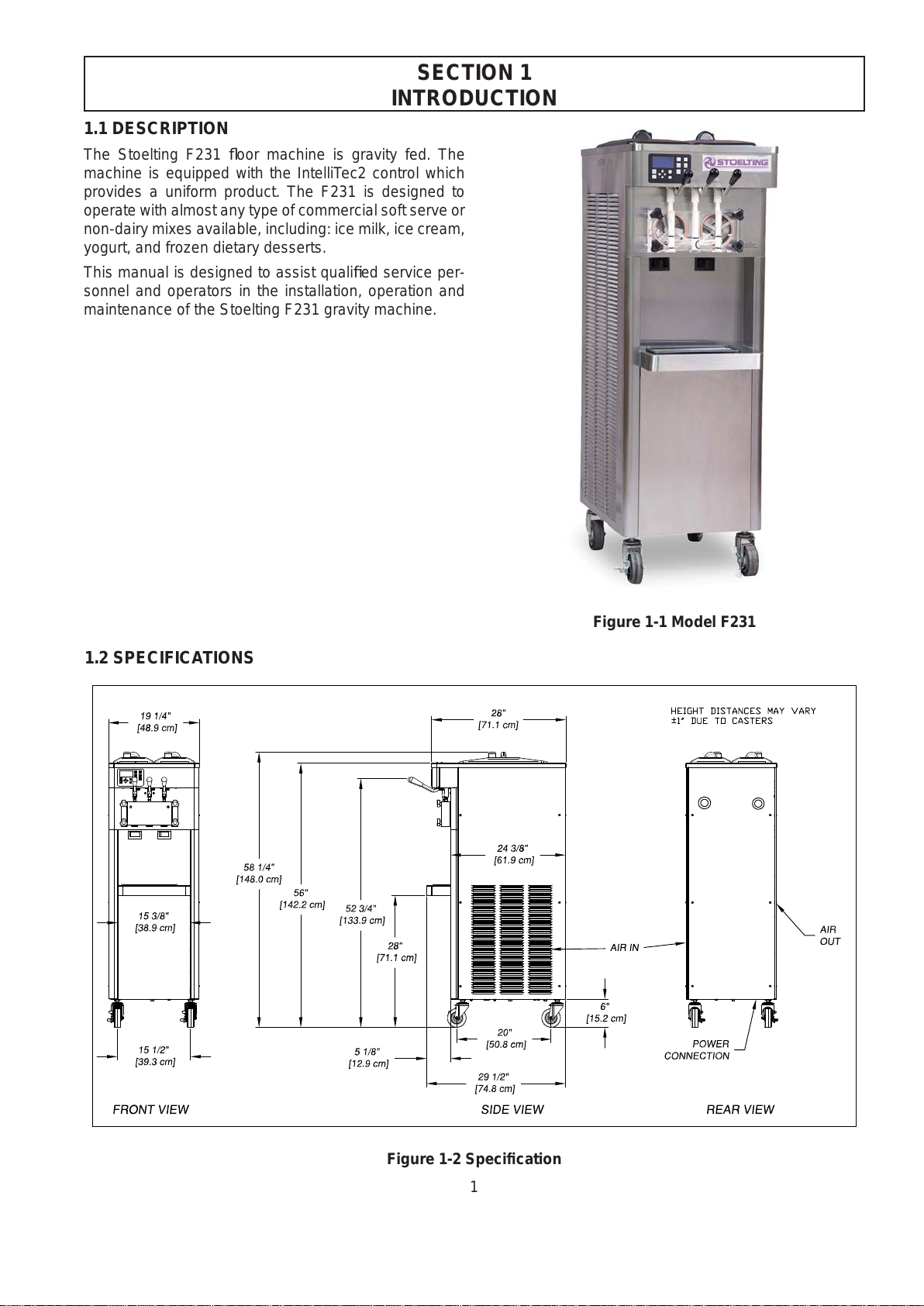
2.3 MACHINE INSTALLATION
WARNING
Installation must be completed by a qualified
electrician/refrigeration specialist.
Incorrect installation may cause personal injury,
severe damage to the machine and will void fac-
tory warranty.
Installation of the machine involves moving the machine
close to its permanent location, removing all crating, set-
ting in place, assembling parts, and cleaning.
A. Uncrate the machine.
B. Install the four casters. Turn the threaded end
intothemachineuntilnothreadsare showing.To
level,turnoutcastersnomorethan1/4”maximum,
then tighten all jam nuts.
C. The machine must be placed in a solid level
position. NOTE
Accurate leveling is necessary for correct drainage
of freezing cylinder and to insure correct overrun.
D. Machines with air cooled condensers require a
minimum of 3” (7,5cm) of space on both sides
for proper circulation.
E. On air cooled machines, install the air baffle to
the bottom of the right side panel. Remove the
panel screws and put the baffle in place. Align
the bottom of the baffle with the floor and tighten
the panel screws (Fig. 2-1).
E. Machines that have a water cooled condenser
require 1/2” NPT supply and drain fittings.
2.4 INSTALLING PERMANENT WIRING
To install wiring follow the steps below:
A. Refer to the nameplate on the side panel of the
machineforspecificelectricalrequirements.Make
sure the power source in the building matches
the nameplate requirements.
B. Remove the back panel and the junction box
cover located at the bottom of the machine.
C. Install permanent wiring according to local code.
Figure 2-1 Installing Baffle
Total Restaurant Supply - https://totalsupply1.com - Toll Free 1-800-944-9304 - Local 507-288-9454
2940 Hwy 14 W, Rochester, MN 55901

4
Total Restaurant Supply - https://totalsupply1.com - Toll Free 1-800-944-9304 - Local 507-288-9454
2940 Hwy 14 W, Rochester, MN 55901

5
SECTION 3
INITIAL SET-UP AND OPERATION
3.1 OPERATOR’S SAFETY PRECAUTIONS
SAFE OPERATION IS NO ACCIDENT; observe these
rules:
A. Know the machine. Read and understand the
Operating Instructions.
B. Notice all warning labels on the machine.
C. Wearproperclothing.Avoidloosefittinggarments,
and remove watches, rings or jewelry that could
cause a serious accident.
D. Maintain a clean work area. Avoid accidents by
cleaning up the area and keeping it clean.
E. Stay alert at all times. Know which switch, push
button or control you are about to use and what
effect it is going to have.
F. Disconnect power for maintenance. Never
attempt to repair or perform maintenance on the
machineuntilthemainelectricalpowerhasbeen
disconnected.
G. Donotoperateunderunsafeoperatingconditions.
Neveroperatethemachineifunusualorexcessive
noise or vibration occurs.
3.2 OPERATING CONTROLS AND INDICATORS
Before operating the machine, it is required that the op-
erator know the function of each operating control. Refer
to Figure 3-1 for the location of the operating controls on
the machine. For the information regarding error codes
displayedonthecontrolpanel,refertothetroubleshooting
section of this manual.
A. INTELLITEC2 TOUCHPAD
Main Power On/Off
The Main Power button is used to supply power to the
IntelliTec2 control, the freezing cylinder circuits and the
storage refrigeration system. When the machine is first
pluggedin,thecontroldefaultstotheOnstatuswithpower
to the hopper only. If the Main Power On/Off button is
pressed when the machine is on, the machine will turn
offand a statusmessagewillbedisplayed on the screen.
WARNING
High voltage will shock, burn or cause death. The
OFF-ONswitchmustbe placed intheOFFposition
priortodisassemblingforcleaningorservicing. Do
not operate machine with panels removed.
Figure 3-1 Machine Controls
IntelliTec2 Control
(See Figure 3-2) Dispense
RateAdjustor
Total Restaurant Supply - https://totalsupply1.com - Toll Free 1-800-944-9304 - Local 507-288-9454
2940 Hwy 14 W, Rochester, MN 55901

6
Help
Pressing the Help button will display help information
dependant on the cursor’s location. Pressing the Help
button again will exit the help screen.
Selection Button (SEL)
The SEL button is used by technicians to select menu
options.
Set Button (SET)
The SET button is used by technicians to save changes
when modifying control settings.
On/Off Button
Power to the freezing cylinders can then be controlled
with the On/Off Left and On/Off Right switches.
Push to Freeze Button
Pressing the PUSH TO FREEZE button initiates “Serve
Mode”.
Clean Button
The CLEAN button initiates “Clean Mode”.
Arrow Buttons ()
The arrow buttons are used by technicians to navigate
through the control readings and settings.
B. SPIGOT SWITCH
Thespigotswitch is mountedtothe spigot camassembly
behind the header panel. When the spigot is opened to
dispenseproduct,thespigotswitchopensandthe“Serve
Mode” begins.
C. DISPENSE RATE ADJUSTOR
The dispense rate adjustor is located under the header
panel,totheimmediaterightofthespigothandles.Turning
theknobcounterclockwisewilldecreasethedispenserate.
D. MIX LOW LIGHTS
The mix low lights are located at the back of the F231.
There is a light for each freezing cylinder. A steady light
signifies a low mix condition. A blinking light signifies an
error. The light will automatically turn off when the condi-
tion has been resolved.
E. USB ACCESS PORT
The USB access port is located on the right side panel
of the machine. The port is used by technicians to import
firmware and export machine statistics.
3.3 DISASSEMBLY OF MACHINE PARTS
Before using the machine for the first time, complete
machine disassembly, cleaning and sanitizing proce-
dures need to be followed. Routine cleaning intervals
and procedures must comply with the local and state
health codes. Inspection for worn or broken parts should
be made at every disassembly of the machine. All worn
or broken parts should be replaced to ensure safety to
boththeoperatorandthe customer and to maintain good
machine performance and a quality product. Check the
wear line on the auger flights on a regular basis (Fig.
3-3) and replace as needed. Frequency of cleaning must
comply with the local health regulations.
To disassemble the machine, refer to the following steps:
A. REMOVING MIX
For the first time cleaning the machine, skip to part B.
Disassembly of Front Door.
1. Press the Clean button. After mix has melted
(about 5 minutes) open the spigot to drain the
mix.
2 Fill the hopper with 2 gallons (8 liters) of cool tap
water.
3. Press the Clean button to run the machine.After
30 seconds press the Clean button again to stop
the auger.
4. Drain the water out of the machine.
NOTE
If the water does not drain clear, repeat steps 2-4.
5. UseStera-Sheenorequivalentsanitizingsolution
mixedaccordingtomanufacturer’sinstructionsto
provide a 100 parts per million strength solution.
Mix sanitizer in quantities of no less than 2
gallonsof 90°to110°F(32°Cto 43°C)water.Any
sanitizer must be used only in accordance with
the manufacturer’s instructions.
6. Pour the sanitizer into the hopper.
7. Using brushes provided, scrub the hopper.
8. After 5 minutes, drain the sanitizer out of the
freezing cylinder.
Figure 3-2 IntelliTec2 Control
Wear Line
Figure 3-3 Auger Flight Wear
Total Restaurant Supply - https://totalsupply1.com - Toll Free 1-800-944-9304 - Local 507-288-9454
2940 Hwy 14 W, Rochester, MN 55901

7
B. DISASSEMBLY OF FRONT DOOR
1. TurnthemachineoffbypressingtheMainFreezer
Power Off/On button on the IntelliTec2 control.
2. Remove the knobs on the front door.
3. Remove the front door by pulling it off the studs.
4. Removethespigotthroughthebottomofthefront
door.
5. Remove all o-rings from parts by first wiping off
thelubricationusingacleantowel.Thensqueeze
the o-ring upward to form a loop (Fig. 3-4). Roll
the o-ring out of the groove.
B. DISASSEMBLY OF AUGER
1. Remove the front auger support and bushing.
2. Remove the auger assembly from the machine.
Pull the auger out of the machine barrel slowly.
Astheaugerisbeingpulledout,carefullyremove
each of the plastic flights with springs.
3. Keep the rear of the auger tipped up once it is
clear of the freezing cylinder to prevent the rear
seal assembly from dropping.
4. Wipethe spline lubricant offofthehexendofthe
auger with a paper towel. Remove the rear seal
assembly (Fig. 3-5).
5. Unscrew the springs from the auger flights.
3.4 CLEANING DISASSEMBLED PARTS
Disassembled machine parts require complete cleaning,
sanitizingandairdryingbeforeassembling.Localandstate
health codes will dictate the procedure required. Some
statehealthcodesrequire a four sink process(pre-wash,
wash,rinse, sanitize,airdry), whileothersrequireathree
sink process (without the pre-wash step). The following
procedures are a general guideline only. Consult your
local and state health codes for the procedures required
in your location.
A. Prepare Stera-Sheen or equivalent cleaner in
2 gallons of 90° to 110°F (32° to 43°C) water
following manufacturers instructions. Place all
parts in the solution and clean with provided
brushes.
B. Rinse all parts with clean 90° to 110°F (32° to
43°C) water.
C. Wash the hopper and freezing cylinder with the
Stera-Sheen solution and brushes provided.
D. Cleantherearsealsurfacesfromtheinsideofthe
freezing cylinder with the Stera-Sheen Solution.
3.5 SANITIZING MACHINE PARTS
A. UseStera-Sheenorequivalentsanitizingsolution
mixedaccordingtomanufacturer’sinstructionsto
provide a 100 parts per million strength solution.
Mix sanitizer in quantities of no less than 2
gallonsof 90°to110°F(32°Cto 43°C)water.Any
sanitizer must be used only in accordance with
the manufacturer’s instructions.
B. Place all parts in the sanitizing solution for 5
minutes, then remove and let air dry completely
before assembling in machine.
3.6 CLEANING THE MACHINE
The exterior should be kept clean at all times to preserve
the luster of the stainless steel.Ahigh grade of stainless
steel has been used on the machine to ease cleanup. To
remove spilled or dried mix, wash the exterior with 90° to
110°F (32°C to 43°C) Stera-Sheen solution or equivalent
cleaner and wipe dry.
Do not use highly abrasive materials, as they will mar the
finish. Use a soft cloth or sponge to apply the solution.
For best results, wipe with the grain of the steel.
A. Clean the rear seal surface from inside of the
freezing cylinder.
Figure 3-4 Removing O-Ring
Figure 3-5 Rear Seal Assembly
Total Restaurant Supply - https://totalsupply1.com - Toll Free 1-800-944-9304 - Local 507-288-9454
2940 Hwy 14 W, Rochester, MN 55901

8
B. Using sanitizing solution and the large barrel
brush provided, sanitize the freezing cylinder by
dipping the brush in the sanitizing solution and
brushing the inside of the freezing cylinder.
NOTE
Do not let sanitizing solution sit overnight in the
freezing cylinder.
C. Remove the drip tray by pulling from the front
panel. Clean and replace the drip tray.
3.7 ASSEMBLING MACHINE
Toassemblethemachineparts,refertothefollowingsteps:
NOTICE
Petrol-Gel sanitary lubricant or equivalent must be
usedwhenlubrication of machinepartsis specified.
NOTICE
The United States Department of Agriculture and
theFoodand DrugAdministration requirethatlubri-
cants used on food processing equipment be certi-
fied for this use. Use lubricants only in accordance
with the manufacturer’s instructions.
A. Assemble all o-rings onto parts dry, without
lubrication. Then apply a thin film of sanitary
lubricant to exposed surfaces of the o-rings.
B. Lubricate the rear seal area on the auger shaft
with a thin layer of sanitary lubricant. Install the
rear seal o-ring. Lubricate the outside of the rear
seal o-ring with sanitary lubricant.
C. Lubricate the inside metal surface of the rear
seal and install it onto the auger shaft. DO NOT
lubricate the outside of the rear auger seal (Fig.
3-6).
D. Lubricate the hex drive end of the auger with a
smallamountofsplinelubricant.Asmallcontainer
of spline lubricant is shipped with the machine.
E. Screw the springs onto the studs in the plastic
flights. The springs must be screwed into the
flightscompletelytoprovidepropercompression.
F. Install the two plastic flights onto the rear of the
auger and insert it part way into the freezing
cylinder.
G. Installtheremainingplasticflights,pushtheauger
into the freezing cylinder and rotate slowly until
the auger engages the drive shaft.
H. Applyathinlayerofsanitarylubricanttotheinside
and outside of the auger support bushing. Install
thebushingontotheaugersupportandinstallthe
auger support into the front of the auger. Rotate
the auger support so that one leg of the support
points straight up.
I. Apply a thin layer of sanitary lubricant to the
o-rings on the spigot body and install the spigot
body through the bottom of the front door.
K. Apply a thin film of sanitary lubricant to the door
seal o-ring and fit it into the groove on the rear
of the front door.
M. Place the front door assembly on the mounting
studsandthepushfrontdooragainstthemachine
carefully.
N. Secure the front door to the machine by placing
the knobs on the studs and tightening until finger
tight.Donotovertighten.Apropero-ringsealcan
be observed through the transparent front door.
3.8 SANITIZING
Sanitizing must be done after the machine is clean and
just before the machine is filled with mix. Sanitizing the
night before is not effective. However, you should always
clean the machine and parts after using it.
NOTE
The United States Department of Agriculture and
the Food and Drug Administration require that all
cleaning and sanitizing solutions used with food
processing equipment be certified for this use.
Whensanitizingthe machine,referto localsanitaryregu-
lationsforapplicablecodesandrecommendedsanitizing
products and procedures. The frequency of sanitizing
must comply with local health regulations. Mix sanitizer
accordingtomanufacturer’sinstructions toprovidea 100
partspermillionstrength solution. Mix sanitizer inquanti-
ties of no less than 2 gallons of 90°F to 110°F (32°C to
43°C) water.Allow sanitizer to contact the surfaces to be
sanitized for 5 minutes. Any sanitizer must be used only
in accordance with the manufacturer’s instructions.
Figure 3-6 Lubricate Rear Seal
Total Restaurant Supply - https://totalsupply1.com - Toll Free 1-800-944-9304 - Local 507-288-9454
2940 Hwy 14 W, Rochester, MN 55901

9
A. Prepare 2 gallons of Stera-Sheen sanitizing
solutionfollowingthemanufacturer’sinstructions.
B. Install the mix inlet regulator into the hopper.
C. Pour the sanitizing solution into the hopper.
D. Makesurethedisplayshowsthefreezingcylinder
is off. If it is not, press the On/Off Left or On/Off
Right button to turn it off.
NOTE
If the freezing cylinder is not off, the control will
not go into Clean mode. This is to protect from ac-
cidentally going into Clean mode.
E. Press the CLEAN button.
F. Check for leaks.
1. Check for leaks at the front door seals.
2. Check the drain tray located under the front
door for leaks coming from the rear of the rear
auger seal.
G. Usingasanitizedsoftbristlebrush(orequivalent)
dipped in sanitizing solution, clean the hopper
sides, mix inlet regulator and underside of the
hopper cover.
H. After five minutes, open the spigot to expel
sanitizing solution. Drain all of the solution from
the machine.
I. Whenthesolutionhasdrained,presstheCLEAN
buttontostoptheauger.Allowthefreezingcylinder
to drain completely.
The machine is now sanitized and ready for adding mix.
3.9 FREEZE DOWN AND OPERATION
A. Sanitize immediately before use.
B. Makesurethedisplayshowsthefreezingcylinder
is off. If it is not, press the On/Off Left or On/Off
Right button to turn it off.
C. Fill the hopper with at least 2.5 gallons of mix.
D. Place a container under the spigot and open the
spigottoallowthemixtoflushoutabout8ounces
(0.23 liters) of sanitizing solution and liquid mix.
E. Press the On/Off button for the cylinder.
F. Press the PUSH TO FREEZE button.
NOTE
After the drive motor starts, there is a 3-second
delay before the compressor starts.
G. When the product is at 75% consistency, the
display will read “SERVE”. Open the spigot to
dispense product.
H. The machine dispenses product at a reasonable
drawrate.If themachineisoverdrawn, theresult
isasoftproductoraproductthatwillnotdispense
at all. If this occurs, allow the machine to run for
approximately30secondsbeforedispensingmore
product.Adispenserateadjustorislocatedunder
the header panel, to the immediate right of the
spigothandle.Turningtheknobcounterclockwise
will decrease the dispense rate.
I. Do not operate the machine when the MIX LOW
message is displayed. Refill the mix container
immediately. NOTE
The control has a standby mode for Serve 1 and
a sleep mode for Serve 1 and Serve 2. After a
preset number of freezing cycles in Serve 1, it will
enter the standby mode (followed by sleep mode)
and remain there until someone draws product or
presses the PUSH TO FREEZE button. In Serve 2
the control directly goes into the Sleep 2 mode. In
the sleep mode, the machine will keep the product
below 41°F (5°C). Sleep modes do not take the
place of cleaning and sanitizing. Federal, State,
andlocalregulatoryagenciesdeterminefrequency
of cleaning and sanitizing.
3.10 FINE CONSISTENCY ADJUSTMENT
If the product consistency needs to be adjusted, use the
Fine ConsistencyAdjustment. To access the setting, the
Associate level password must be entered. Follow the
steps below for the Fine Consistency Adjustment.
A. Press the left arrow from the Current Status
screen.
B. Press the right arrow then the SEL button from
the Password screen. After the password is
accepted,movethecursortotheFineConsistency
Adjustment option and press the SEL button.
C. OntheFineConsistencyAdjustmentscreen,press
the SELbutton and use the arrows to modify the
setting. Adjust the Fine Consistency higher to
increase the consistency or lower to decrease
the consistency.
D. PresstheSETbuttontosavethechanges.Make
adjustments in increments of 5 for best results.
Total Restaurant Supply - https://totalsupply1.com - Toll Free 1-800-944-9304 - Local 507-288-9454
2940 Hwy 14 W, Rochester, MN 55901

10
3.11 MIX INFORMATION
Mix can vary considerably from one manufacturer to
another. Differences in the amount of butterfat content
and quantity and quality of other ingredients have a
direct bearing on the finished frozen product. A change
in machine performance that cannot be explained by a
technical problem may be related to the mix.
Proper product serving temperature varies from one
manufacturer’s mix to another. Mixes should provide a
satisfactory product in the 20°F to 24°F range. Diet and
low-carb mixes typically freeze to proper consistency at
higher temperatures.
When checking the temperature, stir the thermometer in
the frozen product to get an accurate reading.
Oldmix,ormixthathasbeenstoredattoohighatempera-
ture,canresultinafinishedproductthatisunsatisfactory.
To retard bacteria growth in dairy based mixes, the best
storage temperature range is between 33° to 38°F (0.5°
to 3.3° C).
Total Restaurant Supply - https://totalsupply1.com - Toll Free 1-800-944-9304 - Local 507-288-9454
2940 Hwy 14 W, Rochester, MN 55901

11
SECTION 4
MAINTENANCE AND ADJUSTMENTS
Thissectionisintendedtoprovidemaintenancepersonnel
withageneralunderstandingofthemachineadjustments.
It is recommended that any adjustments be made by a
qualified person.
4.1 DRIVE BELT TENSION ADJUSTMENT
To check belt tension, refer to Figure 4-1 and follow the
steps below:
A. Remove the back panel.
B. Use a Burroughs Belt Tension Gauge to set the
tension for the drive belt. Set the belt tension to
35-40 lbs.
C. If an adjustment is necessary, loosen the four
motor plate retaining nuts, adjust belt tension
then retighten the four nuts.
D. Using a straightedge, check that the drive motor
pulley is aligned with the speed reducer pulley.
Align the pulley if necessary.
NOTE
Belt life will be increased if new drive belts are
tightened after two or three weeks of operation.
4.2 CONDENSER CLEANING (AIR-COOLED
MACHINES)
The F231 has an air-cooled or water-cooled condenser.
Theair-cooledcondenserisacoppertubeandaluminum
fin type. Condensing is totally dependent upon airflow. A
pluggedcondenser,orrestrictionsinthelouveredpanelwill
restrict airflow. This will lower the capacity of the system
and damage the compressor. The condenser must be
kept clean of dirt and grease. The machine must have a
minimum of 3” (7.6 cm) of ventilation on the sides of the
unitforfreeflowofair.Makesurethemachineisnotpulling
over 100° F (37° C) air from other equipment in the area.
Thewater-cooledcondenserisatubeandshelltype.The
condenserneedsacool,cleansupplyofwatertoproperly
cool the machine, inlet and discharge lines must be 3/8”
I.D. minimum.
The air-cooled condenser requires periodic cleaning. To
clean, refer to the following procedures.
A. Visually inspect the condenser for dirt.
B. If the condenser is dirty, place a wet towel over
the condenser.
C. Using compressed air or CO2tank, blow out the
dirt from the back of the condenser. Most of the
dirt will cling to the wet towel.
D. Analternativemethodistocleanwithacondenser
brush and vacuum.
NOTE
If the condenser is not kept clean, refrigeration ef-
ficiency will be lost.
4.3 PREVENTATIVE MAINTENANCE
It is recommended that a preventative maintenance
schedule be followed to keep the machine clean and
operating properly. The following steps are suggested as
a preventative maintenance guide.
TheUnitedStatesdepartmentofagricultureandthefood
and drug administration require that lubricants used in
food zones be certified for this use. Use lubricants only
in accordance with the manufacturer’s instructions.
A. Daily checks
Check for any unusual noise or condition and
repair immediately.
B. Monthly checks
Check the condenser for dirt and clean if
necessary.
C. Quarterly Checks
Check drive belts for wear and tighten belts if
necessary.
WARNING
Hazardous voltage
Make sure the machine is off when disassembling
for servicing. The machine must be disconnected
from electrical supply before removing any access
panel.Failureto disconnect power beforeservicing
could result in death or serious injury.
Figure 4-1 Belt Tension Adjustment
Total Restaurant Supply - https://totalsupply1.com - Toll Free 1-800-944-9304 - Local 507-288-9454
2940 Hwy 14 W, Rochester, MN 55901

12
4.4 EXTENDED STORAGE
Refer to the following steps for storage of the machine
over any long period of shutdown time:
A. Clean all the parts that come in contact with mix
thoroughly with a warm detergent water. Rinse
in clear water and dry all parts. Do not sanitize.
NOTE
Do not let cleaning solution stand in the freezing
cylinder or hopper during the shutdown period.
B. Remove, disassemble, and clean the front door,
and auger shaft. Leave disassembled during the
shutdown period.
C. Placetheaugerflightsandaugersupportbushing
inaplastic bagwithamoist papertowel.Thiswill
prevent them from becoming brittle if exposed to
dry air over an extended period of time (over 30
days).
D. Forwater-cooledmachinesthatareleftinunheated
buildings,orbuildingssubjecttofreezing,thewater
must be shut off and disconnected. Disconnect
the water inlet fitting. The fitting is located at the
rearofthemachine.Runthecompressorfor2-3
minutes to open water valve (the front door must
be attached for the compressor to run). Blow
out all water through water inlet. Drain the water
supply line coming to the machine. Disconnect
the water outlet fitting.
E. Press the Main Power On/Off button to turn the
machine off.
F. Disconnect the machine from the source of
electrical supply.
Total Restaurant Supply - https://totalsupply1.com - Toll Free 1-800-944-9304 - Local 507-288-9454
2940 Hwy 14 W, Rochester, MN 55901

13
SECTION 5
TROUBLESHOOTING
5.1 ERROR CODES
When the machine experiences a problem, one of the
following error codes will be displayed on the control
panel. Each error code directs you to the system location
of the malfunction.
ERROR CODE MALFUNCTION
2 High Torque
3 Run Time
4 Clean
5 Freezing Cylinder Sensor
6 HopperSensor(singlehoppermachines)
7 Drive Motor
8 Cab Sensor
9 High Pressure Cutout
10 Auxiliary Sensor
11 Prime (cab units only)
12 Left Hopper Sensor
13 Right Hopper Sensor
21 Spigot Open Time
To return the machine to normal operation, any error
causing condition must be corrected and the power to
the affected freezing cylinder must be cycled. Turn the
power to the freezing cylinder off then back on using the
On/Off button of the affected freezing cylinder.
5.2 TROUBLESHOOTING
Error Code 2 - High Torque
If the control panel displays a High Torque Error
(E2),thecontrollerhassensedthatthedrivemotor
is running at a high load for 10 or more seconds.
This may be due to the product consistency
adjustment being set too high. Press the On/Off
button for the cylinder to turn it off, wait until the
product in the freezing cylinder thaws and then
turn the cylinder back on. If the error persists,
contact your Authorized Stoelting Distributor for
further assistance.
Error Code 3 - Run Time
The Run Time Error (E3) occurs when the
compressor runs continuously for an extended
period. This error is generally caused by very
low mix levels in the hopper or from product
breakdown.Anothercommoncauseresultsfrom
a restriction preventing mix from entering the
freezing cylinder. Check the mix in the hopper.
If the level mix is low, add mix. If there is a
possibility that the mix has broken down, clean
and sanitize the machine and replace the mix
with fresh product.
Ice crystals in the hopper can clog the mix inlet
systemandpreventmixfromenteringthefreezing
cylinder.Thoroughlythawmixpermanufacturer’s
recommendations.Tocheckforicecrystals,pour
asmall amountofproductfromthemixcontainer
through a clean and sanitized sieve or strainer.
If ice crystals are in the mix, check temperature
of the walk-in cooler where the mix is stored.
In air cooled machines, the Run Time Error
may indicate that airflow within the machine
has reduced or stopped. Check the sides of the
machine for anything that would restrict airflow.
If the error persists after attempting to clear it,
contact your Authorized Stoelting Distributor for
further assistance.
Error Code 4 - Clean
If the machine is left in the Clean Mode for more
than 20 minutes, the control panel will display a
CleanError(E4).Thisconditiondoesnotreflecta
problem with the machine itself. The Clean Error
has been programmed into the controller as a
safeguard to protect the machine from potential
damagecausedbythemachinebeingaccidentally
left in "Clean Mode". To clear the Clean Error,
press the On/Off button for the cylinder to turn if
off then back on.
Total Restaurant Supply - https://totalsupply1.com - Toll Free 1-800-944-9304 - Local 507-288-9454
2940 Hwy 14 W, Rochester, MN 55901

14
Error Code 5 - Freezing Cylinder Sensor
TheFreezingCylinderSensorError(E5)indicates
a failure of the barrel sensor or if the sensor is
out of range. If the control panel displays an E5,
press the On/Off button for the cylinder to turn
if off then back on. If the error persists, contact
your Authorized Stoelting Distributor for further
assistance. NOTE
Whenthemachineencountersa Freezing Cylinder
SensorError, themachinewillcontinue to runusing
preset timers. This mode will allow the operator to
continue serving product until the machine can be
serviced.
ErrorCode6-HopperSensor(singlehoppermachines)
The Hopper Sensor Error (E6) will not occur on
the machine.
Error Code 7 - Drive Motor
If the control panel displays a Drive Motor Error
(E7), the control does not sense current coming
from the drive motor. Press the On/Off button
for the cylinder to turn if off then back on. If the
error persists, contact your Authorized Stoelting
Distributor for further assistance.
Error Code 8 - Cab Sensor
A Cab Sensor Error (E8) will not occur on the
machine.
Error Code 9 - High Pressure Cutout
High Pressure Cutout Errors (E9) are usually
caused by a dirty or inefficient condenser. If the
control panel displays an E9 on an air cooled
machine, check for proper air clearance around
the machine. If there is an E9 on a water cooled
machine check for proper flow from the water
supply or kinks in the hoses.
If the error persists, contact your Authorized
Stoelting Distributor for further assistance.
Error Code 10 - Auxiliary Sensor
An Auxiliary Temperature Sensor Error (E10)
occurs if the temperature sensor on the control
boardfails.PresstheOn/Offbuttonforthecylinder
to turn if off then back on. If the error persists,
contact your Authorized Stoelting Distributor for
further assistance
Error Code 11 - Prime Error
The Prime Error (E11) will not occur on the
machine.
Error Code 12 - Left Hopper Sensor
The Left Hopper Sensor Error (E12) indicates
a failure of the hopper sensor or if the sensor is
outof range.Ifthe controlpaneldisplaysanE12,
press the On/Off button for the cylinder to turn
if off then back on. If the error persists, contact
your Authorized Stoelting Distributor for further
assistance.
Error Code 13 - Right Hopper Sensor
The Right Hopper Sensor Error (E13) indicates
a failure of the hopper sensor or if the sensor is
outof range.Ifthe controlpaneldisplaysanE12,
press the On/Off button for the cylinder to turn
if off then back on. If the error persists, contact
your Authorized Stoelting Distributor for further
assistance.
Error Code 21 - Spigot Open Time
The Spigot Open Time Error (E21) indicates a
failure of the spigot switch. If the control senses
thespigotisopencontinuouslyfor10minutes,the
machine will go into Sleep 3 mode. If the control
panel displays an E21, press the On/Off button
for the cylinder to turn if off then back on. If the
error persists, contact your Authorized Stoelting
Distributor for further assistance.
Total Restaurant Supply - https://totalsupply1.com - Toll Free 1-800-944-9304 - Local 507-288-9454
2940 Hwy 14 W, Rochester, MN 55901
Other manuals for F231
1
Table of contents
Other Stoelting Commercial Food Equipment manuals
Popular Commercial Food Equipment manuals by other brands

Lotus
Lotus LIBR.ISTR.PC CF110E Installation and operating instructions

STODDART
STODDART Woodson W.CFSSN23 Specification, installation and operation manual

UBC
UBC CENTAUR 2.1 manual

Dover
Dover Hillphoenix PF-H Installation & operation manual

Electrolux
Electrolux 1 Service manual

Fri-Jado
Fri-Jado Hot CC user manual

Salvis
Salvis Smartline ABM1 BI371854 operating instructions

Omcan
Omcan JE-ES-0028N-T instruction manual

Diamond
Diamond RVE/6C-CM user manual

Aesculap
Aesculap FAV5 Instructions for use/Technical description

TRENT
TRENT CaterSense-02 Installation and commissioning instructions

Trueheat
Trueheat Salamander S86 Installation, operation and service manual