StoneAge AUTOSTROKE AST-200-V2 User manual

AUTOSTROKE™(AST-200-V2)
FOR USE WITH THE AUTOBOX®PRODUCT LINE
USER MANUAL
PL 629-V2 REV E
(02/2019)

2866-795-1586 • WWW.STONEAGETOOLS.COM
MANUFACTURER’S INFORMATION................................................................ 2
SPECIFICATIONS ........................................................................................ 3
DESCRIPTION OF EQUIPMENT AND INTENDED USE ................................... 3
KEY FEATURES........................................................................................... 3
CE DECLARATION OF INCORPORATION ..................................................... 4
WARNING AND SAFETY INSTRUCTIONS ....................................................... 6
OPERATOR TRAINING................................................................................. 6
PERSONAL PROTECTIVE EQUIPMENT REQUIREMENTS.............................. 6
PRE-RUN SAFETY CHECK .......................................................................... 7
SYSTEM ASSEMBLY - OVERVIEW .................................................................. 8
ABX-2L AND ABX-2L-V2 MANIFOLD UPGRADE............................................. 10
AUTOSTROKE AIR MANIFOLD CONVERSION OVERVIEW ............................ 10
REMOVAL OF MANIFOLD AND INSTALLATION OF CONVERSION ................. 11
SPLICING THE TUBING FOR THE T-FITTINGS .............................................. 12
ABX-2L AND ABX-2L-V2 AUTOSTROKE SET-UP ............................................ 13
ABX-3L AND ABX-3L-V2 AUTOSTROKE SET-UP ............................................ 15
OPERATION...................................................................................................... 17
MAINTENANCE ................................................................................................ 18
STORAGE, TRANSPORTATION, AND HANDLING ........................................... 18
AIR MOTOR GENERATOR REPLACEMENT INSTRUCTIONS.......................... 19
PART DIAGRAMS ............................................................................................. 22
TERMS AND CONDITIONS .............................................................................. 26
TABLE OF CONTENTS

3
866-795-1586 • WWW.STONEAGETOOLS.COM
DESCRIPTION OF EQUIPMENT AND
INTENDED USE
The AutoStroke (AST-200-V2) is an accessory for the Autobox®ABX-
2L, ABX-2L-V2, ABX-3L, and ABX-3L-V2, that can be mounted to
both Autobox®Control Boxes. The AutoStroke detects when the
lance encounters a blockage in a tube and retracts the lance for a
set time before continuing forward again, allowing the banshee to
continue to rotate and reducing potential hose damage.
KEY FEATURES:
• Air motor generator allows operation with compressed air as
opposed to batteries.
• Automatically retracts lance when blockage is encountered.
• Adjustable hose push force.
• Adjustable retract time.
• Switch allows disabling functionality when not desired.
• Mounts on CB stand and connects in line with Autobox®ABX-
2L, ABX-2L-V2, ABX-3L, and ABX-3L-V2L forward, reverse,
and clamp, airlines with two additional signal lines from the ABX
unit.
SPECIFICATIONS
AutoStroke (AST-200-V2)
Weight:
18 lbs
(8.2 kg)
AutoStroke (AST-200-V2)
Dimensions:
16.9” Long x 11.7” Tall x 7.9” Wide
(429 mm x 297mm x 201mm)
Air Pressure: 40 to 125 psi
(2.8 to 8.6 bar)
Air Consumption: 3 CFM
(5 m³/hr)
StoneAge Inc.
466 S. Skylane Drive
Durango, CO 81303, USA
Phone: 970-259-2869
Toll Free: 866-795-1586
www.stoneagetools.com
StoneAge Europe
Unit 2, Britannia Business Centre
Britannia Way
Malvern WR14 1GZ
United Kingdom
Phone: +44 (0) 1684 892065
This manual must be used in accordance with all applicable national laws. The manual shall be regarded as a part of the machine
and shall be kept for reference until the nal dismantling of the machine, as dened by applicable national law(s).
Updated manuals can be downloaded at:
https://www.stoneagetools.com/manuals
MANUFACTURER’S INFORMATION

4866-795-1586 • WWW.STONEAGETOOLS.COM
EU DECLARATION OF CONFORMITY
Manufacturer: StoneAge Incorporated
466 South Skylane Drive
Durango, CO 81303
USA
Authorized Representative: StoneAge Europe
Unit 2, Britannia Business Centre
Britannia Way
Malvern WR14 1GZ
United Kingdom
Steve Ellis, Director StoneAge Europe
Declare that: AutoStroke (AST-200-V2) blockage detector accessory
for high pressure water cleaning of system parts.
Is compliant with the following Directives and Standards:
Directive 2006/42/EC (Machinery Directive)
EN ISO 12100:2010 (E) Safety of machinery – General principles for design – Risk assessment and risk reduction
2011/65/EU Restriction of Hazardous Substances (RoHS2) Directive.
EN 61326-1:2013 Electrical equipment for measurement, control and laboratory use - EMC requirements-Part 1:General requirements
The Technical File for AutoStroke (AST-200-V2) is maintained at:
StoneAge Incorporated, 466 South Skylane Drive, Durango, CO 81303, USA and was compiled by the Engineering Manager.
The Technical File is available through the Authorized Representative.
This Declaration of Conformity is issued under the exclusive responsibility of StoneAge Incorporated.
________________________________________ 02/11/2019
StoneAge Incorporated, Durango, CO, USA Date
Adam Markham, Engineering Manager, Robotics

5
866-795-1586 • WWW.STONEAGETOOLS.COM
NOTES
This page is intentionally left blank.

6866-795-1586 • WWW.STONEAGETOOLS.COM
PERSONAL PROTECTIVE EQUIPMENT REQUIREMENTS
Use of Personal Protective Equipment (PPE) is dependent on
the working pressure of water and the cleaning application.
Managers, Supervisors, and Operators MUST carry out a job
specic risk assessment to dene the exact requirements for
PPE. See Protective Equipment for Personnel (Section 6) of
WJTA-IMCA’s Recommended Practices For The Use Of High-
pressure Waterjetting Equipment for additional information.
Hygiene - Operators are advised to wash thoroughly after all
waterjetting operations to remove any waterblast residue which
may contain traces of harmful substances.
First aid provision - users MUST be provided with suitable rst
aid facilities at the operation site.
PPE may include:
• Eye protection: Full face visor
• Foot protection: Kevlar® brand or steel toe capped,
waterproof, non-slip safety boots
• Hand protection: Waterproof gloves
• Ear protection: Ear protection for a minimum of 85 dBA
• Head protection: Hard hat that accepts a full face visor
and ear protection
• Body protection: Multi-layer waterproof clothing approved
for waterjetting
• Hose protection: Hose shroud
• Respiratory protection: May be required; refer to job
specic risk assessment
OPERATOR TRAINING
Managers, Supervisors, and Operators MUST be trained in Health
and Safety Awareness of High-pressure Water Jetting and hold
a copy the Water Jetting Association (WJA) Code of Practice, or
equivalent (see www.waterjetting.org.uk).
Operators MUST be trained to identify and understand all applicable
standards for the equipment supplied. Operators should be trained
in manual handling techniques to prevent bodily injury.
Operators MUST read, understand, and follow the Operational and
Training Requirements (Section 7.0) of WJTA-IMCA’s Recommended
Practices For The Use Of High-pressure Waterjetting Equipment, or
equivalent.
Operators MUST read, understand and follow the Warnings,
Safety Information, Assembly, Installation, Connection, Operation,
Transport, Handling, Storage, and Maintenance Instructions detailed
in this manual.
StoneAge has designed and manufactured this equipment
considering all hazards associated with its operation. StoneAge
assessed these risks and incorporated safety features in the design.
StoneAge WILL NOT accept responsibility for the results of misuse.
IT IS THE RESPONSIBILITY OF THE INSTALLER/OPERATOR
to conduct a job specic risk assessment prior to use. Job specic
risk assessment MUST be repeated for each different set up,
material, and location.
The risk assessment MUST conform to the Health and Safety at
Work Act 1974 and other relevant Health and Safety legislation.
The risk assessment MUST consider potential material or substance
hazards including:
• Aerosols
• Biological and microbiological (viral or bacterial) agents
• Combustible materials
• Dusts
• Explosion
• Fibers
• Flammable substances
• Fluids
• Fumes
• Gases
• Mists
• Oxidizing Agents
WARNING AND SAFETY INSTRUCTIONS

7
866-795-1586 • WWW.STONEAGETOOLS.COM
WARNING AND SAFETY INSTRUCTIONS
WARNING
Operations with this equipment can be potentially hazardous.
Caution MUST be exercised prior to and during machine and water
jet tool use. Please read and follow all of these instructions, in addition
to the guidelines in the WJTA Recommended Practices handbook,
available online at www.wjta.org. Deviating from safety instructions
and recommended practices can lead to severe injury and/or death.
• Do not exceed the maximum operating pressure specied for
any component in a system.
• The immediate work area MUST be marked off to keep out
untrained persons.
• Inspect the equipment for visible signs of deterioration,
damage, and improper assembly. Do not operate if damaged,
until repaired.
• Make sure all threaded connections are tight and free of leaks.
• The AutoStroke (AST-200-V2) is an accessory to the
AUTOBOX
®
ABX-2L, ABX-2L-V2, ABX-3L, and ABX-3L-V2.
Users of the AUTOBOX
®
ABX-2L, ABX-2L-V2, ABX-3L, and
ABX-3L-V2 MUST be trained and/or experienced in the use
and application of high-pressure technology and cleaning,
as well as all associated safety measures, according to the
WJTA Recommended Practices for the use of High-pressure
Waterjetting Equipment.
• The Control Box should be located in a safe location where the
Operator has good visibility of the AUTOBOX
®
ABX-2L, ABX-
2L-V2, ABX-3L, and ABX-3L-V2.
• The AUTOBOX
®
ABX-2L, ABX-2L-V2, ABX-3L, ABX-3L-V2,
AutoStroke (AST-200-V2), and Control Box MUST be
supervised at all times and should never be left unattended.
• Test the Control Box before operating the AUTOBOX
®
ABX-2L,
ABX-2L-V2, ABX-3L, ABX-3L-V2, and AutoStroke (AST-200-V2)
with high-pressure water to verify the control valves move the
hose in the intended direction, and that the dump valve and
hose clamp are working properly. See the “Operation” section
of this manual for adjustment settings.
• Always de-energize the system before opening the door to
service or replace any parts. Failure to do so can result in severe
injury and/or death.
PRE-RUN SAFETY CHECK
Refer to WJTA-IMCA’s, Recommended Practices For The Use Of
High-pressure Waterjetting Equipment and/or The Water Jetting
Association’s, WJA Code of Practice for additional safety information.
• Complete a job specic risk assessment and act on the resulting
actions.
• Adhere to all site specic safety procedures.
• Ensure the waterblasting zone is properly barricaded and that
warning signs are posted.
• Ensure the work place is free of unnecessary objects (e.g. loose
parts, hoses, tools).
• Ensure all Operators are using the correct Personal Protective
Equipment (PPE).
• Check that the air hoses are properly connected and tight.
• Check all hoses and accessories for damage prior to use. Do
not use damaged items. Only high quality hoses intended for
waterblast applications should be used as high-pressure hoses.
• Check all high-pressure threaded connections for tightness.
• Test the Control Box before operating the AUTOBOX
®
ABX-2L
ABX-2L-V2, ABX-3L, ABX-3L-V2, and AutoStroke (AST-200-V2)
with high-pressure water to verify the control valves move the
hose in the intended direction, and that the dump valve and
hose clamp are working properly. See the “Operation” section
of this manual for adjustment settings.
• Ensure that Operators never connect, disconnect, or tighten
hoses, adapters, or accessories with the high-pressure water
pump unit running.
• Ensure no personnel are in the hydroblasting zone.
WARNING AND SAFETY INSTRUCTIONS
8866-795-1586 • WWW.STONEAGETOOLS.COM
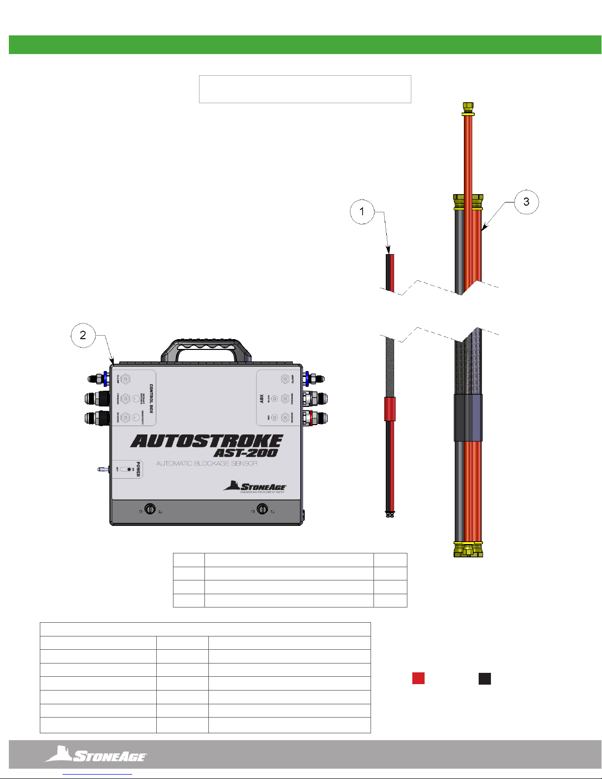
SYSTEM ASSEMBLY - OVERVIEW
TOOLS REQUIRED FOR INSTALLATION
TOOL SIZE WHERE USED
ALLEN WRENCH HEX KEY 5/32” FLAT HEAD CAP SCREWS
CLOSED END BOX WRENCH 7/16” HEX HEAD BOLTS AND QUICK DISCONNECT FITTINGS
OPEN END BOX WRENCH 9/16” 1/4 JIC FITTINGS ON HOSE ENDS
OPEN END BOX WRENCH 3/4” JIC FITTING ASSEMBLIES ON MANIFOLD
OPEN END BOX WRENCH 7/8” 1/2 JIC FITTINGS ON HOSE ENDS
LOCTITE®567 PIPE DOPE OR TAPE - ALL NEW OR REPLACED TAPERED PIPE FITTINGS
NOTE: THIS COLOR CODE
SYSTEM IS USED THROUGH THE
SYSTEM FOR TUBE AND HOSE
CONNECTIONS AND COLOR I.D.
FORWARD
REVERSE
# DESCRIPTION QTY
1AST 277-25 AUTOSTROKE™ UMBILICAL ASSEMBLY 1
2 AST 301-V2 AUTOSTROKE™ BOX WITH GENERATOR 1
3 AST 340 AUTOSTROKE™ HOSE BUNDLE ASSY 1
AUTOSTROKE™(AST-200-V2)
AUTOMATIC BLOCKAGE SENSOR
9
866-795-1586 • WWW.STONEAGETOOLS.COM
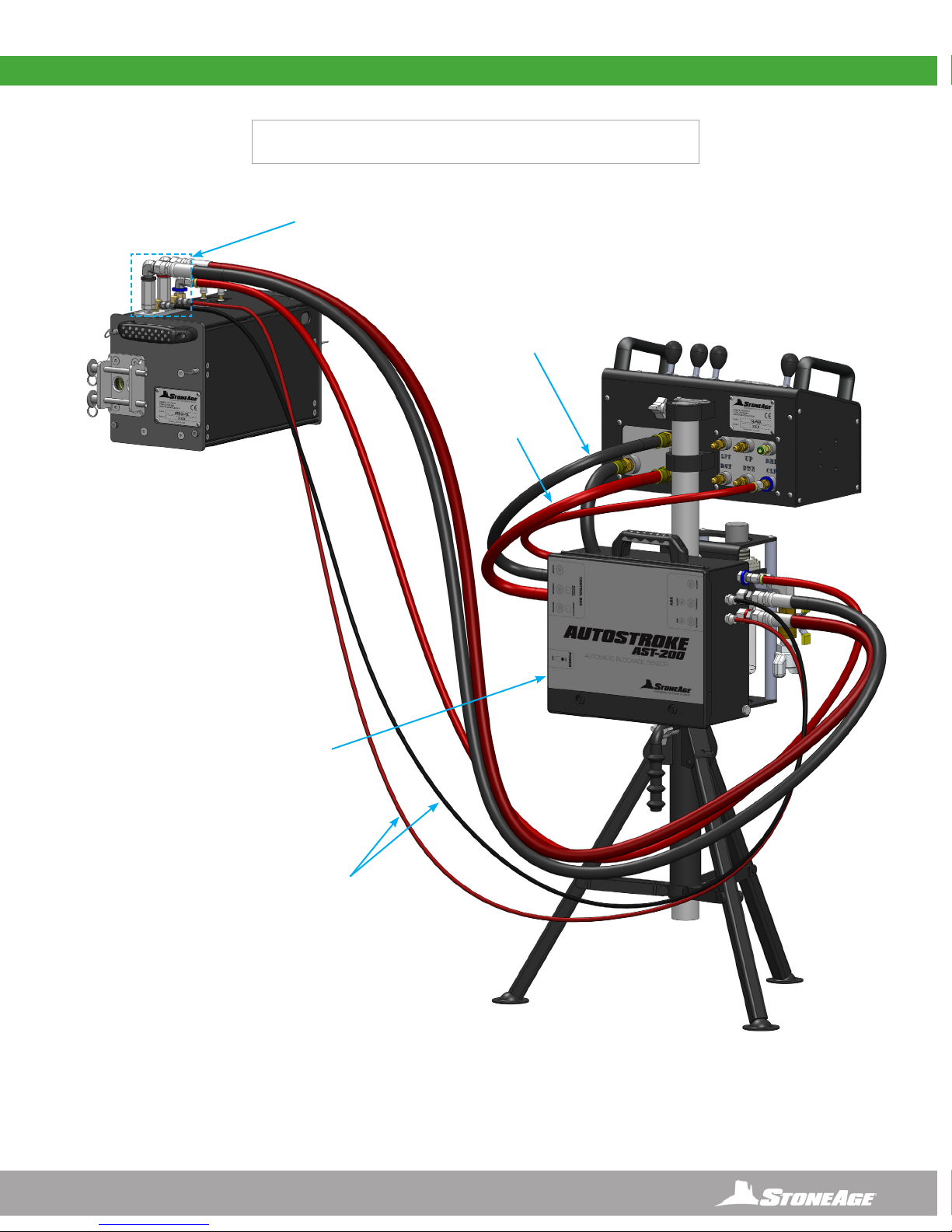
SYSTEM ASSEMBLY - OVERVIEW
AUTOSTROKE™
(AST 275)
MANIFOLD
ASSEMBLY
AUTOSTROKE™
(AST-200-V2)
ASSEMBLY
AUTOSTROKE™
(AST-200-V2)
HOSE, FORWARD
AUTOSTROKE™
(AST-200-V2)
HOSE, REVERSE
1/4” TUBING LINES
(COME BUNDLED IN NYLON SHEATH)
AUTOSTROKE™(AST-200-V2)
SHOWN WITH AUTOBOX® ABX-2L AND CB-ABX ASSEMBLY

10 866-795-1586 • WWW.STONEAGETOOLS.COM
ABX-2L AND ABX-2L-V2 MANIFOLD UPGRADE
THE AUTOSTROKE AIR MANIFOLD CONVERSION OVERVIEW
This conversion guide describes how to replace the Air Manifold and add T-connections in order to provide necessary air signals from the
ABX-2L and ABX-2l-V2 to the AutoStroke. This rst step is mandatory to allow the AutoStroke AST-200-V2 to function with the Autobox®
ABX-2L and ABX-2L-V2.
THE AUTOSTROKE AIR MANIFOLD CONVERSION PARTS KIT
The parts below are included in the AST 275 AutoStroke Air Manifold Conversion Kit.
ORIGINAL
AIR MANIFOLD
ABX-2L AND
ABX-2L-V2
BEFORE
ABX-2L AND
ABX-2L-V2
AFTER
AUTOSTROKE
AIR MANIFOLD
AUTOSTROKE Air Manifold Assembly
Quick Disconnect Fittings
NOTICE
The Autobox® ABX-3L and ABX-3L-V2 come ready to hook-up to the AutoStroke and therefore this upgrade is NOT necessary for the
Autobox® ABX-3L and ABX-3L-V2.

11
866-795-1586 • WWW.STONEAGETOOLS.COM
FIGURE 1
ABX-2L AND ABX-2L-V2 MANIFOLD UPGRADE
REMOVING THE ABX-2L AIR MANIFOLD
1. Remove the 4 at head cap screws from the Top Plate using a 5/32 Allen wrench hex key. Set the Top Plate and screws aside, and open
the Side Door. (FIGURE 1)
2. Unplug the three tubes from the bottom of the manifold (FIGURE 2) and remove the 2 hex head bolts using a 7/16 socket driver or box
wrench. Remove and retain the top 3 JIC tting assemblies, and disconnect the 3 air tubes from the bottom of the Air Manifold. Discard
the old manifold. (FIGURE 3)
FIGURE 2
INSTALLING THE AUTOSTROKE AIR MANIFOLD CONVERSION
1. Install the 3 JIC tting assemblies to the new AutoStroke Air Manifold. Use pipe dope or tape on the NPT tapered threads. Re-attach the
air manifold using the 2 hex head bolts that were reserved from the original manifold assembly. (FIGURE 1)
2. Reconnect the 3 air tubes (blue, red, and black) to the push-to-connect ttings on the bottom of the air manifold. (FIGURE 2)
FIGURE 3
FIGURE 2FIGURE 1
DISCONNECT

12 866-795-1586 • WWW.STONEAGETOOLS.COM
ABX-2L AND ABX-2L-V2 MANIFOLD UPGRADE
SPLICING THE TUBING FOR THE T-FITTINGS
1. Disconnect the red and black air tubes from the ttings on the left side of the ow controls. (FIGURE 1) Cut exactly 2 inches off the end of
the red tube and 3 inches off the black tube. (FIGURE 2)
2. Connect the red and black tubes with the T-ttings from the manifold to the ttings on the left side of the ow controls. Connect the
other end of the T-ttings to the end of the cut tubing. The tubes from the manifold assembly should lie between the ow control knobs.
(FIGURE 3)
3. Attach the Top Plate and close the Side Door Assembly. (FIGURE4)
4. Install the two Quick Disconnect Fittings to the brass elbows using pipe dope or tape on the tapered threads. (FIGURE 5)
FIGURE 1 FIGURE 2
FIGURE 4
FIGURE 3
FIGURE 5
COMPLETED
OR
Remove 3”
Remove 2”
CONNECT T-FITTINGS

13
866-795-1586 • WWW.STONEAGETOOLS.COM
FIGURE 2
ABX-2L AND ABX-2L-V2 AUTOSTROKE SET-UP
CONNECTING THE AST-200-V2 AUTOSTROKE TO THE CB-ABX CONTROL BOX
1. Disconnect the air hose from the back of the Control Assembly. Loosen the Thumb Screw on the Pole Mount on the Control Assembly.
Carefully lift the Control Assembly off of the Mounting Pole and put aside. (Figure 1)
2. Slide the AutoStroke Assembly onto the Mounting Pole and hand tighten the Thumb Screw. Then slide the Control Assembly back
onto the Mounting Pole. Align the Thumb Screw with the top hole on the Mounting Pole and hand tighten. (Figure 2)
3. Connect the air hose from the FRL to the back of the Control Assembly. (Figure 3)
DISCONNECT
FIRST
THUMB
SCREW
POLE
MOUNT
MOUNTING
POLE
THUMB
SCREW
CONTROL
ASSEMBLY
AUTOSTROKE
ASSEMBLY
FIGURE 1 FIGURE 2 COMPLETE
FIGURE 3
14 866-795-1586 • WWW.STONEAGETOOLS.COM
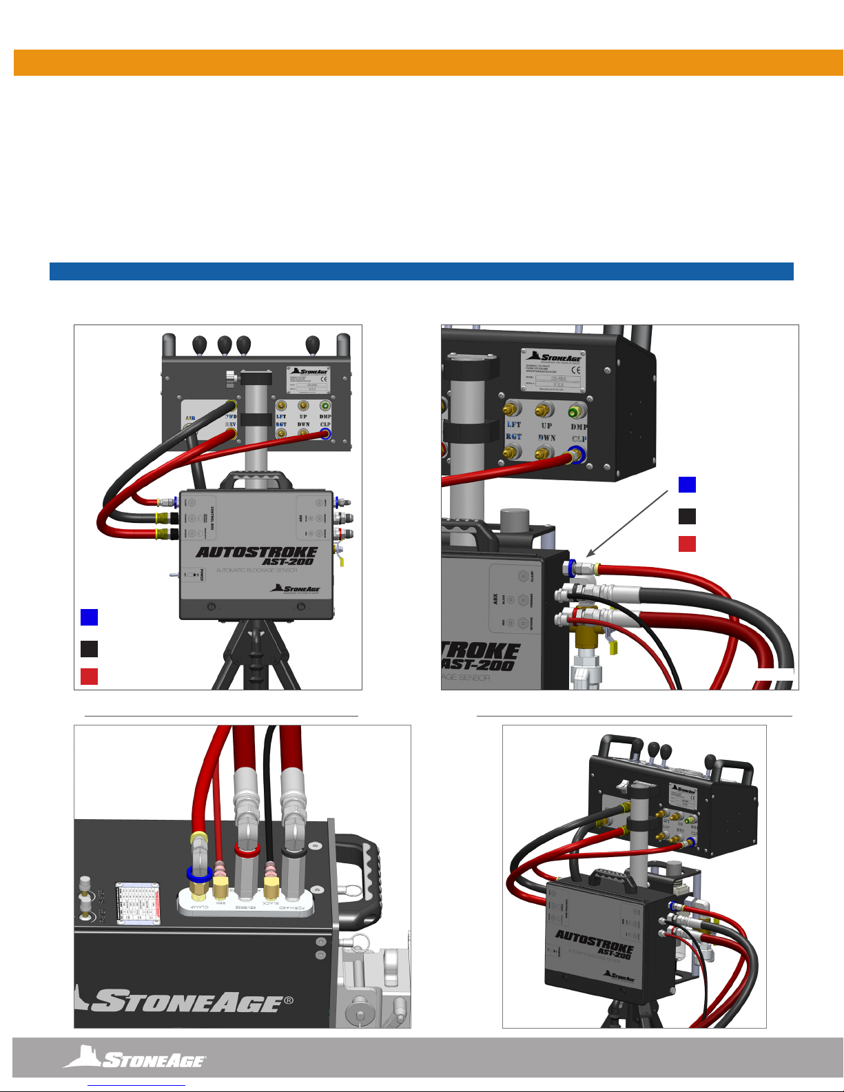
HOSE CONNECTIONS
1. Connect the BLACK and RED 1/2” lines from the AutoStroke “Forward” and “Reverse” connections to the “Forward” and “Reverse”
connections on the back of the CB-ABX. Connect the SHORT 1/4” I.D. Hose to the tting marked “CLAMP” on the left side of the
AutoStroke to the “CLAMP” tting on the Control Box. (Figure 1)
2. Connect the LONG 1/4” I.D. Hose to the tting marked “CLAMP” on the right side of the AutoStroke and the opposite end to the
“CLAMP” tting on the ABX-2L or ABX-2L-V2. Insert the ends of the 1/4” BLACK and RED tubing into the press lock ttings on the
right side of the AutoStroke. Push the opposite ends of each tube into the color labeled, press lock, ttings on the manifold atop the
ABX-2L or ABX-2L-V2. Connect the BLACK and RED 1/2” lines to the right side of the AutoStroke marked “Forward” and “Reverse”
and connect the opposite ends to the manifold on the ABX-2L or ABX-2L-V2. (Figure 2 & 3)
3. Skip to the “OPERATIONS” page of this manual.
FIGURE 2
CORRECT AUTOSTROKE CONNECTION TO ABX-2L
ABX-2L AND ABX-2L-V2 AUTOSTROKE SET-UP
FIGURE 1
FORWARD
REVERSE
CLAMP TO
AUTOSTROKE
FORWARD
REVERSE
CLAMP TO
ABX-2L
FIGURE 3
NOTICE
The AutoStroke and the CB-ABX are labeled “Forward” and “Reverse”and color coded. Make sure the hoses mate to their corresponding
labeled connections on both ends.
CORRECT AUTOSTROKE CONNECTION TO CONTROL BOX

15
866-795-1586 • WWW.STONEAGETOOLS.COM
ABX-2L AND ABX-2L-V2 AUTOSTROKE SET-UP ABX-3L AND ABX-3L-V2 AUTOSTROKE SET-UP
CONNECTING THE AST-200-V2 AUTOSTROKE TO THE CBX-ABX CONTROL BOX
1. Disconnect the air hose from the back of the Control Assembly. Loosen the Thumb Screw on the Pole Mount and carefully lift the
Control Assembly off of the Mounting Pole. Put the Control Assembly aside. (Figure 1)
2. Slide the AutoStroke Assembly onto the Mounting Pole, with the Decal side facing away from the FRL. Then hand tighten the Thumb
Screw. Then slide the Control Assembly back onto the Mounting Pole. Then hand tighten the Thumb Screw to secure the Control
Assembly to the Mounting Pole. (Figure 2)
3. Connect the air hose from the FRL to the back of the Control Assembly. (Figure 3)
DISCONNECT
FIRST
THUMB
SCREW
POLE
MOUNT
MOUNTING
POLE
THUMB
SCREW
CONTROL
ASSEMBLY
AUTOSTROKE
ASSEMBLY
FIGURE 1 FIGURE 2 COMPLETE
FIGURE 3

16 866-795-1586 • WWW.STONEAGETOOLS.COM
CORRECT AUTOSTROKE
CONNECTION TO CONTROL BOX
CORRECT AUTOSTROKE
CONNECTION TO ABX-3L OR ABX-3L-V2
FIGURE 3
ABX-3L AND ABX-3L-V2 AUTOSTROKE SET-UP
NOTICE
The AutoStroke and the CBX-ABX are labeled “Forward” and “Reverse”and color coded. Make sure the hoses mate to their corresponding
labeled connections on both ends.
FIGURE 2
FORWARD
REVERSE
CLAMP TO
CONTROL BOX
FIGURE 1
FORWARD
REVERSE
CLAMP TO
CONTROL BOX
HOSE CONNECTIONS
1. Connect the BLACK and RED 1/2” lines from the AutoStroke “Forward” and “Reverse” connections to the “Forward” and “Reverse”
connections on the back of the CBX-ABX. Connect the SHORT 1/4” I.D. Hose to the tting marked “CLAMP” on the left side of the
AutoStroke to the “CLAMP” tting on the Control Box. (Figure 1)
2. Connect the LONG 1/4” I.D. Hose to the tting marked “CLAMP” on the right side of the AutoStroke and the opposite end to the
“CLAMP” tting on the ABX-3L or ABX-3L-V2. Insert the ends of the 1/4” BLACK and RED tubing into the press lock ttings on the
right side of the AutoStroke. Push the opposite ends of each tube into the color labeled, press lock, ttings on the manifold atop the
ABX-3L or ABX-3L-V2. Connect the BLACK and RED 1/2” lines to the right side of the AutoStroke marked “Forward” and “Reverse”
and connect the opposite ends to the manifold on the ABX-3L or ABX-3L-V2. (Figure 2 & 3)

17
866-795-1586 • WWW.STONEAGETOOLS.COM
OPERATION
AUTOSTROKE AST-200-V2 FUNCTIONS
• With the AutoStroke in the “OFF” Position, run the Autobox Tractor in Reverse until the Air Motor Generator goes silent. This may take up
to one minute and will allow the Air Motor Generator to charge.
• Turn the AutoStroke toggle to the “ON” Position and make sure the power light comes on.
• To setup the AutoStroke turn the SENSITIVITY knob all the way in the counter-clockwise direction. (Increase turn clockwise, Decrease
turn counter-clockwise)
• Next position your nozzles so they hit the tube sheet face and run them into the tube sheet. While holding the feed in lever increase the
sensitivity until it just starts to peck at the tube sheet face.
• Adjust the RETRACT DISTANCE (Increase turn clockwise, Decrease turn counter-clockwise) until you like how far it is retracting the
nozzles.
• The AutoStroke is now operational.
+ -
+ -

18 866-795-1586 • WWW.STONEAGETOOLS.COM
The AutoStroke™ (AST-200-V2) should be stored in a dry location between jobs. Before storing the unit, use compressed air to blow out
any debris and moisture. Use mild soapy water to clean the machine in order to remove corrosive materials. Apply a small amount of air
tool oil directly into the forward and reverse ttings. Install the dust caps onto all ttings to keep moisture and dirt out.
STORAGE, TRANSPORTATION, AND HANDLING
Contact StoneAge for Safety Data Sheets for material usage and any other pertinent information that may be required.
MAINTENANCE
Maintenance Item Frequency Maintenance Required
Air Motor Generator Replacement When Needed If the Air Motor Generator fails on the AutoStroke, it is possible to replace
it. Please call your StoneAge Customer Service Representative to order
part number AMG-100-V2 AIR MOTOR GENERATOR, WITH FITTINGS.
Follow the Air Motor Generator Replacement instructions located in this
manual
All Air Fittings After each use Reinstall all dust caps to protect from dirt and moisture.
Air Lines Before each use Blow out before making connections to the AutoStroke
Electrical Connections Frequently Visually inspect for corrosion.
MAINTENANCE
NOTICE
Electronic components are not user serviceable. If troubleshooting the system fails it must be sent back to StoneAge Tools for service.
Contact your customer service representative. 1-866-795-1586
Problem Solution
AST-200 is not functioning -Check that airlines are connected properly
-Check that switch is on and red LED is lit while feeding forward
-Increase sensitivity
-Verify that fuse is not blown
AST-200 continues to reverse feed -Check that hose is not getting hung up behind the ABX
-Reduce sensitivity
-Reduce hose drag
AST-200 power light is not coming on but the
switch is in the “ON” positon
- Toggle rhe AutoStroke to the “OFF” Position, run the Autobox Tractor in Reverse until the
Air Motor Generator goes silent. This may take up to one minute and will allow the Air Motor
Generator to charge. The charge time could be longer with lower pressures.
TROUBLESHOOTING
19
866-795-1586 • WWW.STONEAGETOOLS.COM
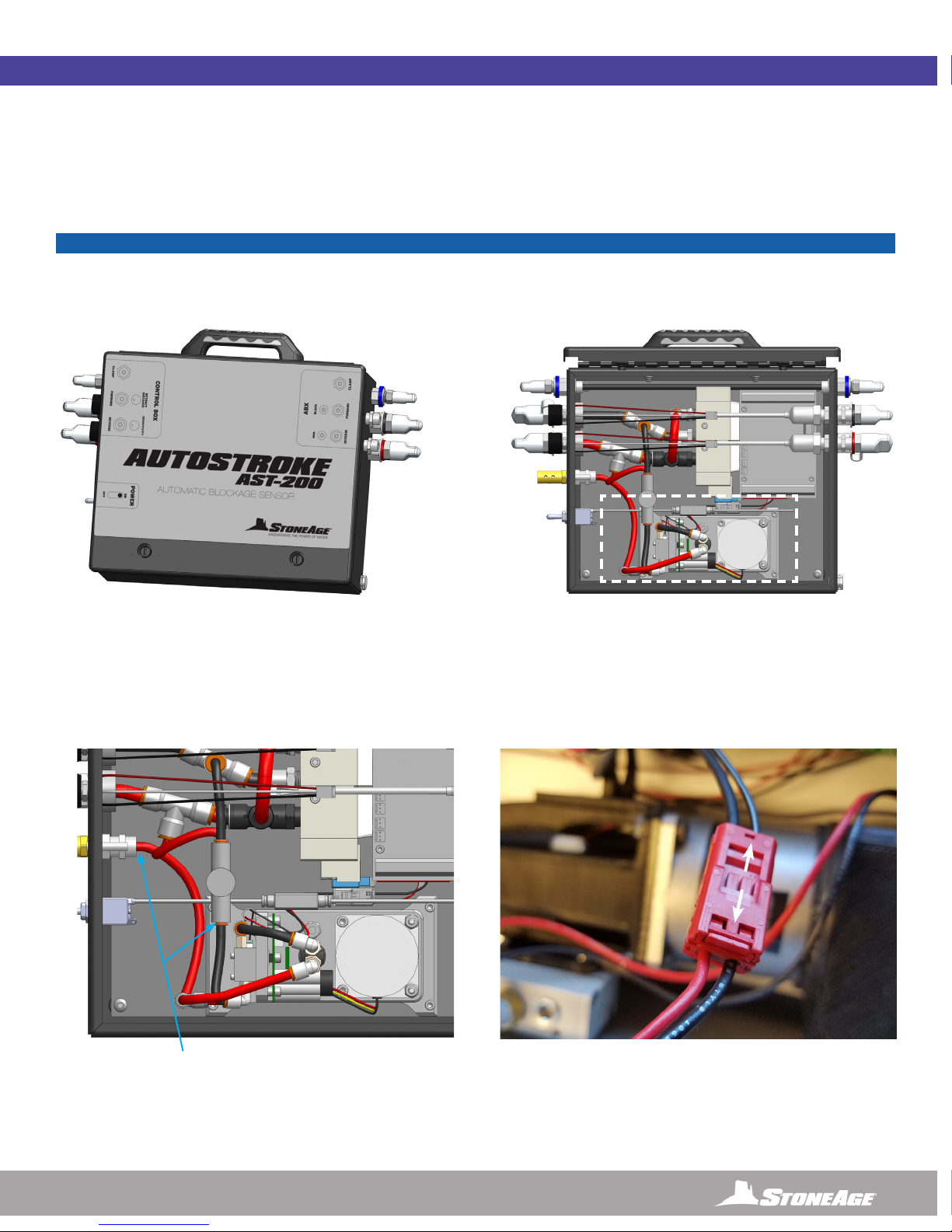
AIR MOTOR GENERATOR REPLACEMENT INSTRUCTIONS
These replacement instructions describe how to replace an air motor generator within an AST-200-V2 AutoStroke.
AIR MOTOR GENERATOR REMOVAL INSTRUCTIONS
AIR MOTOR GENERATOR REPLACEMENT
NOTICE
Airline connections should be removed at least 10 minutes before servicing to allow time for stored electrical energy to dissipate.
1. Using a at screwdriver, turn the quarter turn latches
counterclockwise 90 degrees and open the AutoStroke
enclosure.
2. Disconnect the 2 air tubes from the air motor generator
AST-200-V2 AUTOSTROKE shown without cover
Air Motor Generator location
3. Depress the tab on the back of the electrical
connector and carefully separate the electrical
connection.

20 866-795-1586 • WWW.STONEAGETOOLS.COM
AIR MOTOR GENERATOR REPLACEMENT
4. Remove the four screws securing the Air Motor
Generator with a 9/64” Hex Key
5. Remove the Air Motor Generator from the AutoStroke enclosure.
AIR MOTOR GENERATOR REMOVAL INSTRUCTIONS.....CONTINUED
AIR MOTOR GENERATOR INSTALLATION INSTRUCTIONS
1. Install the replacement Air Motor Generator into the AutoStroke
enclosure as shown.
2. Install the four screws securing the air motor generator
with a 9/64” Hex Key.
3. Carefully reconnect he electrical connection.
Table of contents
Popular Accessories manuals by other brands

HAMPTON BAY
HAMPTON BAY HB-7310-03 Use and care guide

BM PRO
BM PRO SmartSense Installing

Audio Control
Audio Control The Epicenter Plus owner's manual

Master cool
Master cool MMBT12 Installation and operation manual

Silvercrest
Silvercrest HG02989A Operation and safety notes

Ninestars
Ninestars DZT-50-6 user manual


RAISE 3D
RAISE 3D N2 installation guide

Heath Zenith
Heath Zenith Wireless Push Button Accessory 598-1151-02 owner's manual

Life Smart
Life Smart LS086WH quick start guide

Best Choice Products
Best Choice Products SKY5472 instruction manual

MD SPORTS
MD SPORTS Meijer Assembly instructions

BJ Live
BJ Live BJ-234 user guide