StoneAge Sentinel LWPS-100-X User manual
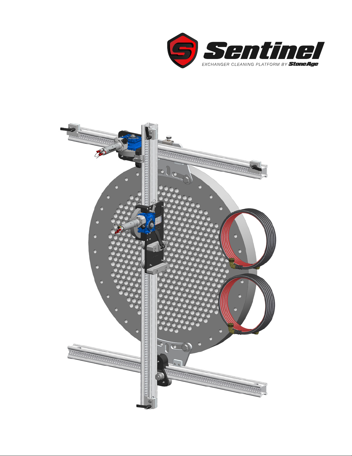
PL 690 REV B
(09/2021)
LIGHTWEIGHT POSITIONER
(LWPS-100-X)
USER MANUAL

2866-795-1586 • WWW.STONEAGETOOLS.COM
MANUFACTURER’S INFORMATION .......................................... 3
SPECIFICATIONS ........................................................................................ 3
DESCRIPTION OF EQUIPMENT AND INTENDED USE ................................... 3
KEY FEATURES........................................................................................... 3
EC AND UKCA DECLARATIONS OF CONFORMITY....................................... 4 - 5
WARNING AND SAFETY INSTRUCTIONS .................................... 6
OPERATOR TRAINING................................................................................. 6
PERSONAL PROTECTIVE EQUIPMENT REQUIREMENTS.............................. 6
SAFETY LABEL DEFINITIONS....................................................................... 6
PRE-RUN SAFETY CHECK .......................................................................... 7
PRODUCT OVERVIEWS ....................................................... 8
LIGHTWEIGHT POSITIONER SYSTEM.......................................................... 8
LIGHTWEIGHT POSITIONER AND ACCESSORIES ........................................ 9
LIGHTWEIGHT POSITIONER CLAMP STYLES .............................................. 10
LIGHTWEIGHT POSITIONER SET-UP ......................................... 11
LIGHTWEIGHT POSITIONER ASSEMBLY...................................................... 11
LIGHTWEIGHT POSITIONER CONNECTIONS TO POWER HUB..................... 13
SHOTGUN MOUNT INSTALLATION .............................................................. 14
MAINTENANCE................................................................ 15
STORAGE, TRANSPORTATION, AND HANDLING ............................ 15
PARTS DIAGRAMS ............................................................ 15
TERMS AND CONDITIONS.................................................... 28
WARRANTY ................................................................... 29
TABLE OF CONTENTS

3
866-795-1586 • WWW.STONEAGETOOLS.COM
MANUFACTURER’S INFORMATION
SPECIFICATIONS
Imperial Metric
Full Positioner Weight 120 lbs 54.4 kg
Vertical Carriage Weight 17 lbs 7.7 kg
Horizontal Carriage Weight 15.4 lbs 7 kg
Idler Carriage Weight 4.4 lbs 2 kg
Dimensions without extensions 6 x 6 ft 1829 x 1829 mm
Cleaning Window Dimensions for 6ft Rail Conguration See diagram below table
Optional Rail Extension lengths 2, 4, and 6 ft 607, 1219, and 1829 mm
DESCRIPTION OF EQUIPMENT
AND INTENDED USE
The Lightweight Positioner can be
mounted to a variety of heat exchanger
tube bundles and has pneumatic
powered horizontal and vertical drives.
It is intended to be used with these
AUTOBOX® Hose Tractors;
• ABXS-3L (3 Lance with Sentinel
Technology)
• ABX-3L (3 Lance)
• ABX-2L-B (2 Lance Belt Drive)
• ABX-PRO (Single Lance)
KEY FEATURES:
• Better positioning accuracy - reduced
backlash and clearance across the
system
• Completely tool free setup and
operation
• Drives locked in place by a pin for
visual conrmation of engagement
• Highly accurate position encoding
• Reduced component size and weight
• Larger usable widow size
• Push-to-Connect ttings
• Metric hardware and tube sizes
• Sensor can be replaced in minutes
• Same sensor used in both drives
• Carriages are interchangeable with
LWP-500
• Rail scraper on idler carriage
• Utilizes eld proven stainless steel air
motors
72.3in
(1837mm)
Vertical Rail
Length
72.3in
(1837mm)
Horizontal
Rail Length
53.5in
(1360mm)
Maximum
Vertical Travel
2.0in
(51mm) Lower Beam Offset to Insure Idler Carriage
Remains Fully Engaged on Lower Horizontal Rail
13.7in
(347mm)
18.8in
(478mm)
58.2in
(1478mm)
Maximum
Horizontal Travel
This manual must be used in accordance with all applicable national laws. The manual
shall be regarded as a part of the machine and shall be kept for reference until the nal
dismantling of the machine, as dened by applicable national law(s). Updated manuals can
be downloaded at: https://www.stoneagetools.com/manuals
StoneAge Inc.
466 S. Skylane Drive
Durango, CO 81303, USA
Phone: 970-259-2869
Toll Free: 866-795-1586
www.stoneagetools.com
StoneAge NL
Reedijk 7Q
3274 KE Heinenoord
Netherlands
(+31) (0) 85 902 73 70
StoneAge UK
Unit 3
Crucible Business Park
Woodbury Lane
Norton
Worcester
Worcestershire, WR5 2DQ
United Kingdom
+44 (0) 1684 892065

4866-795-1586 • WWW.STONEAGETOOLS.COM
EC DECLARATION OF CONFORMITY
Manufacturer: StoneAge Incorporated
466 South Skylane Drive
Durango, CO 81303
USA
Authorized Representative: StoneAge Europe
Reedijk 7Q
3274 KE Heinenoord
Netherlands
Bob Van Wordragen, Operations Manager StoneAge NL
Declare that: Light Weight Positioner (LWPS-100-X)
for mounting and positioning hose tractors to heat exchangers.
Is compliant with the following Directives and Standards:
EU- Machinery Directive (2006/42/EC)
EU- RoHS Directive (2011/65/EU)
EU- EMC Directive (2014/30/EU)
EN ISO 12100:2010 (e) Safety of machinery – General principles for design – Risk assessment and risk reduction
EN ISO 4414:2010 (en) Pneumatic Fluid Power – General rules and safety requirements for systems and components
EN 55011:2009 Industrial, scientic and medical equipment - Radio-frequency disturbance characteristics - Limits and methods of measurement
EN 60204-1:2018 Safety of machinery– Electrical equipment of machines
This device complies with part 15 of the FCC rules and Industry Canada ICES-003. Operation is subject to the following two conditions:
(1) This device may not cause harmful interference, and (2) this device must accept any interference received, including interference that may cause
undesired operation.
The Technical File for Light Weight Positioner (LWPS-100-X) is maintained at: StoneAge Incorporated, 466 South Skylane Drive, Durango, CO
81303, USA and was compiled by the Director of Engineering and Technology. The Technical File is available through the Authorized Representative.
This Declaration of Conformity is issued under the exclusive responsibility of StoneAge Incorporated.
________________________________________ 09/29/2021
StoneAge Incorporated, Durango, CO, USA Date
Scott Howell, New Product Introduction Manager

5
866-795-1586 • WWW.STONEAGETOOLS.COM
UK DECLARATION OF CONFORMITY
Manufacturer: StoneAge Incorporated
466 South Skylane Drive
Durango, CO 81303
USA
Authorized Representative: StoneAge UK
Unit 3
Crucible Business Park
Woodbury Lane
Norton
Worcester
Worcestershire, WR5 2DQ
United Kingdom
Steve Ellis, Managing Directory StoneAge UK
Declare that: Light Weight Positioner (LWPS-100-X)
for mounting and positioning hose tractors to heat exchangers.
Is compliant with the following Directives and Standards:
S.I. 2008:1597 - Supply of Machinery (Safety) Regulations 2008
S.I. 2012:3032 - Restriction of the Use of Certain Hazardous Substances in Electrical and Electronic Equipment Regulations 2012
S.I. 2016:1091 - Electromagnetic Compatibility Regulations 2016
S.I. 2008:1597 Safety of machinery – General principles for design – Risk assessment and risk reduction
S.I. 2008:1597 Pneumatic Fluid Power – General rules and safety requirements for systems and components
S.I. 2016:1091 Industrial, scientic and medical equipment - Radio-frequency disturbance characteristics - Limits and methods of measurement
S.I. 2016:1091 Safety of machinery– Electrical equipment of machines
S.I. 2016:1091 Electromagnetic Compatibility (EMC) standard for radio equipment and services; Part 1: Common technical requirements;
Harmonized Standard for Electromagnetic Compatibility
The Technical File for Light Weight Positioner (LWPS-100-X) is maintained at:
StoneAge Incorporated, 466 South Skylane Drive, Durango, CO 81303, USA and was compiled by the Engineering Manager.
The Technical File is available through the Authorized Representative.
This Declaration of Conformity is issued under the exclusive responsibility of StoneAge Incorporated.
________________________________________ 09/29/21
StoneAge Incorporated, Durango, CO, USA Date
Scott Howell, New Product Introduction Manager

6866-795-1586 • WWW.STONEAGETOOLS.COM
WARNING AND SAFETY INSTRUCTIONS
OPERATOR TRAINING
Managers, Supervisors, and Operators MUST be trained in Health
and Safety Awareness of High-pressure Water Jetting and hold
a copy the Water Jetting Association (WJA) Code of Practice, or
equivalent (see www.waterjetting.org.uk).
Operators MUST be trained to identify and understand all applicable
standards for the equipment supplied. Operators should be trained
in manual handling techniques to prevent bodily injury.
Operators MUST read, understand, and follow the Operational and
Training Requirements (Section 7.0) of WJTA-IMCA’s Recommended
Practices For The Use Of High-pressure Waterjetting Equipment, or
equivalent.
Operators MUST read, understand and follow the Warnings,
Safety Information, Assembly, Installation, Connection, Operation,
Transport, Handling, Storage, and Maintenance Instructions detailed
in this manual.
StoneAge has designed and manufactured this equipment
considering all hazards associated with its operation. StoneAge
assessed these risks and incorporated safety features in the design.
StoneAge WILL NOT accept responsibility for the results of misuse.
IT IS THE RESPONSIBILITY OF THE INSTALLER/OPERATOR
to conduct a job specic risk assessment prior to use. Job specic
risk assessment MUST be repeated for each different set up,
material, and location.
The risk assessment MUST conform to the Health and Safety at
Work Act 1974 and other relevant Health and Safety legislation.
The risk assessment MUST consider potential material or substance
hazards including:
• Aerosols
• Biological and microbiological (viral or bacterial) agents
• Combustible materials
• Dusts
• Explosion
• Fibers
• Flammable substances
• Fluids
• Fumes
• Gases
• Mists
• Oxidizing Agents
WARNING AND SAFETY INSTRUCTIONS
PERSONAL PROTECTIVE EQUIPMENT REQUIREMENTS
Use of Personal Protective Equipment (PPE) is dependent on
the working pressure of water and the cleaning application.
Managers, Supervisors, and Operators MUST carry out a job
specic risk assessment to dene the exact requirements for PPE.
See Protective Equipment for Personnel (Section 6) of WJTA-
IMCA’s Recommended Practices For The Use Of High-pressure
Waterjetting Equipment for additional information.
Hygiene - Operators are advised to wash thoroughly after all
waterjetting operations to remove any waterblast residue which may
contain traces of harmful substances.
First aid provision - users MUST be provided with suitable rst aid
facilities at the operation site.
PPE may include:
• Eye protection: Full face visor
• Foot protection: Kevlar® brand or steel toe capped,
waterproof, non-slip safety boots
• Hand protection: Waterproof gloves
• Ear protection: Ear protection for a minimum of 85 dBA
• Head protection: Hard hat that accepts a full face visor and
ear protection
• Body protection: Multi-layer waterproof clothing approved for
waterjetting
• Hose protection: Hose shroud
• Respiratory protection: May be required; refer to job specic
risk assessment
SAFETY LABEL DEFINITION
The Lightweight Positioner (LWPS-100-X) has the
potential to cause serious injury if ngers, hair, or
clothing become caught between the rollers and the
rails.

7
866-795-1586 • WWW.STONEAGETOOLS.COM
WARNING
Operations with this equipment can be potentially hazardous.
Caution MUST be exercised prior to and during machine and water
jet tool use. Please read and follow all of these instructions, in addition
to the guidelines in the WJTA Recommended Practices handbook,
available online at www.wjta.org. Deviating from safety instructions
and recommended practices can lead to severe injury and/or death.
• Do not exceed the maximum operating pressure specied for
any component in a system.
• The immediate work area MUST be marked off to keep out
untrained persons.
• Inspect the equipment for visible signs of deterioration,
damage, and improper assembly. Do not operate if damaged,
until repaired.
• Make sure all threaded connections are tight and free of leaks.
• Users of the Lightweight Positioner (LWPS-100-X) MUST be
trained and/or experienced in the use and application of high-
pressure technology and cleaning, as well as all associated
safety measures, according to the WJTA Recommended
Practices for the use of High-pressure Waterjetting Equipment.
• An anti-withdrawal device (back-out preventer) MUST be used
at all times. The back-out prevention device is the Hose Stop
Collet located within the Hose Guide Assembly. StoneAge
offers several different size Hose Stop Collets. The Collet Size
Reference guide is located on the Hose Guide Assembly.
• The Control Box should be located in a safe location where
the Operator has good visibility of the pipe and hose. The
Lightweight Positioner (LWPS-100-X) and Control Box MUST
be supervised at all times and should never be left unattended.
• Always de-energize the system before servicing or replacing any
parts. Failure to do so can result in severe injury and/or death.
• When moving the Lightweight Positioner (LWPS-100-X) lift with
care to prevent bodily injury.
PRE-RUN SAFETY CHECK
Refer to WJTA-IMCA’s, Recommended Practices For The Use Of
High-pressure Waterjetting Equipment and/or The Water Jetting
Association’s, WJA Code of Practice for additional safety information.
• Complete a job specic risk assessment and act on the resulting
actions.
• Adhere to all site specic safety procedures.
• Ensure the waterblasting zone is properly barricaded and that
warning signs are posted.
• Ensure the work place is free of unnecessary objects (e.g. loose
parts, hoses, tools).
• Ensure all Operators are using the correct Personal Protective
Equipment (PPE).
• Check that the air hoses are properly connected and tight.
• Check all hoses and accessories for damage prior to use. Do
not use damaged items. Only high quality hoses intended for
waterblast applications should be used as high-pressure hoses.
• Check all high-pressure threaded connections for tightness.
• **Ensure that a anti-withdrawal device (back-out
preventer), whip checks (hose whips), and all other
applicable safety devices are installed and set-up
properly.**
• Ensure the doors of the Lightweight Positioner (LWPS-100-X)
are closed and securely latched.
• Test the Control Box before operating the Lightweight Positioner
(LWPS-100-X) with high-pressure water to verify the control
valves move the hose in the intended direction, and that the
dump valve and hose clamp are working properly.
• Ensure that Operators never connect, disconnect, or tighten
hoses, adapters, or accessories with the high-pressure water
pump unit running.
• Ensure no personnel are in the hydroblasting zone.
WARNING AND SAFETY INSTRUCTIONSWARNING AND SAFETY INSTRUCTIONS
8866-795-1586 • WWW.STONEAGETOOLS.COM
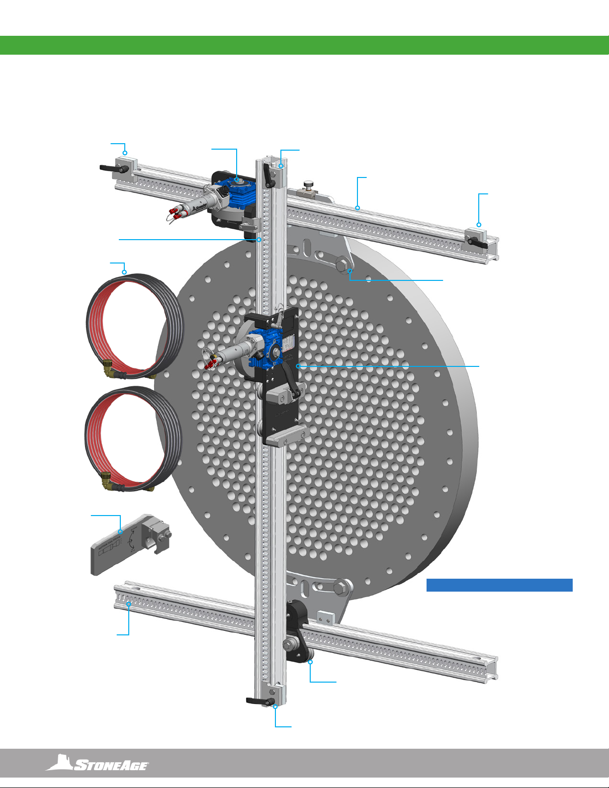
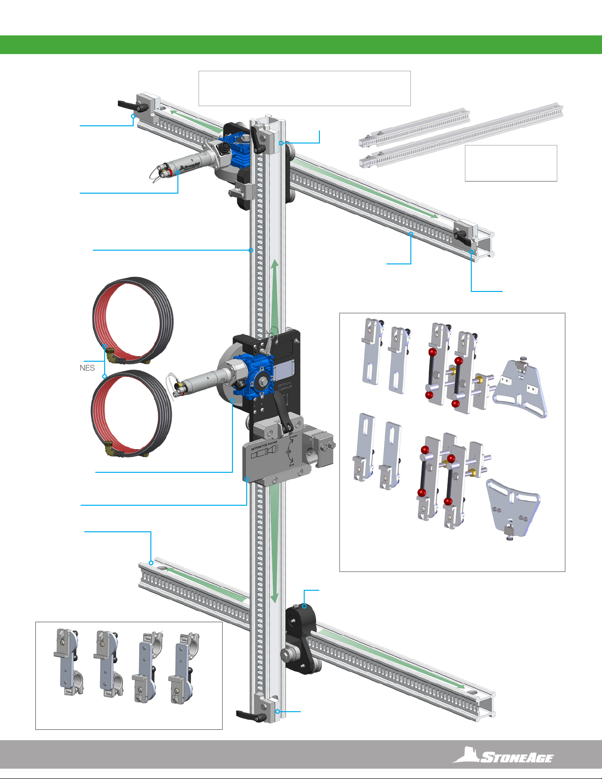
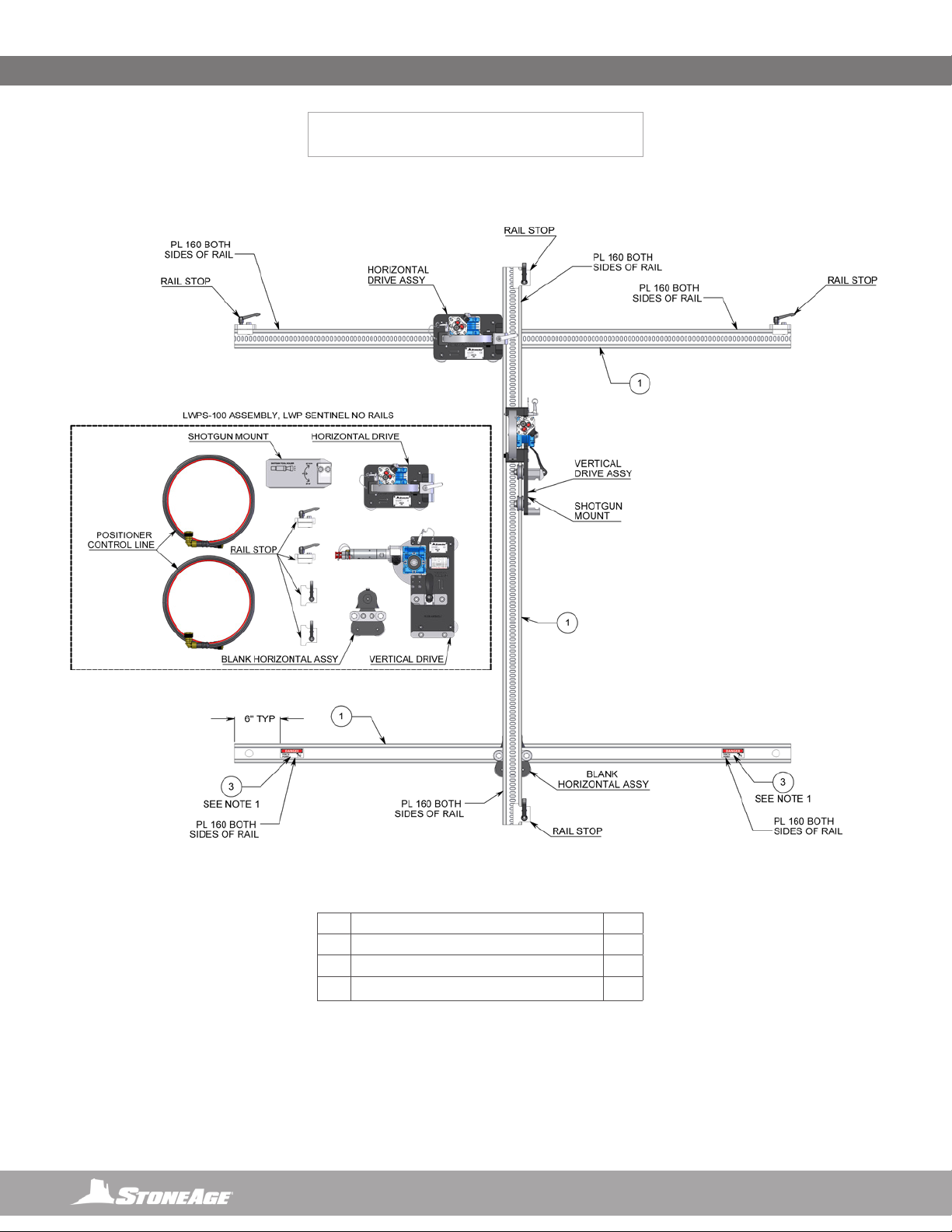
LIGHTWEIGHT POSITIONER ASSEMBLY
(LWPS-100-X)
SYSTEM ASSEMBLY - OVERVIEW
RAIL STOP
RAIL STOP
RAIL STOP
HORIZONTAL DRIVE
ASSEMBLY
SHOT GUN
MOUNT
VERTICAL DRIVE
ASSEMBLY
IDLER
CARRIAGE
ASSEMBLY
RAIL STOP
CLAMP (SEE THE NEXT
PAGE FOR ALTERNATE
CLAMP STYLES)
2.5” SLOTTED RAIL
2.5” SLOTTED RAIL
POSITIONER
CONTROL LINES
2.5” SLOTTED RAIL
NOTICE
Heat exchanger tube bundle face,
shown for graphic representation only.
Not included in assembly
9
866-795-1586 • WWW.STONEAGETOOLS.COM
LIGHTWEIGHT POSITIONER
WITH SENTINEL TECHNOLOGY
AND ACCESSORIES
HORIZONTAL DRIVE
ASSEMBLY
VERTICAL DRIVE
ASSEMBLY
VERTICAL
SLOTTED RAIL HORIZONTAL
SLOTTED RAIL
HORIZONTAL
SLOTTED RAIL
SHOT GUN
MOUNT
RAIL STOP
ASSEMBLY
RAIL STOP
ASSEMBLY
RAIL STOP
ASSEMBLY
RAIL STOP
ASSEMBLY
IDLER CARRIAGE
ASSEMBLY
RAIL EXTENSIONS
(2,4, OR 6 FT LENGTHS)
(.61 m, 1.2 m, OR 1.8 m)
LIGHTWEIGHT POSITIONER - OVERVIEW
SLOTTED
QUICK CLAMP
(LWP 620 KIT
CONTAINS 4)
QUICK CLAMP
(LWP 621 KIT
CONTAINS 4)
PLATE CLAMP
(LWP 622 KIT
CONTAINS 2)
CLAMP TYPES
(LWP 625 KIT
INCLUDES ALL KITS
SHOWN HERE)
15ft (4.572m)
POSITIONER
CONTROL LINES
SCAFFOLD QUICK CLAMP
(LWP 554-K KIT CONTAINS 4)
10 866-795-1586 • WWW.STONEAGETOOLS.COM
CLAMP SELECTION is dependent upon the heat exchanger geometry, bolt holes, hole spacing, and ange accessibility.
QUICK CLAMPS (LWP 518) are for use with heat exchanger anges that provide a robust clamping surface or if ange holes are
inaccessible. Align clamps on the surface of the ange to maximize ange engagement to clamps. (Figure 1)
SLOTTED QUICK (LWP 552) AND PLATE CLAMPS (LWP 519) are for use with heat exchanger anges that have easily accessible
bolt holes. Use quick clamps or plate clamps, depending on the spacing of the hole pattern. (Figures 1 & 3)
SCAFFOLD QUICK CLAMPS (LWP 554) are for use with scaffolding in situations
where they may be no way to clamp directly onto the heat exchanger. (Figure 4)
FIGURE 1
FIGURE 2 FIGURE 3
FIGURE 4
LIGHTWEIGHT POSITIONER CLAMP STYLES
SLOTTED QUICK CLAMP
(LWP 620 KIT CONTAINS 4)
SCAFFOLD QUICK CLAMP
(LWP 554-K KIT CONTAINS 4)
QUICK CLAMP
(LWP 621 KIT CONTAINS 4)
PLATE CLAMP
(LWP 622 KIT
CONTAINS 2)
11
866-795-1586 • WWW.STONEAGETOOLS.COM
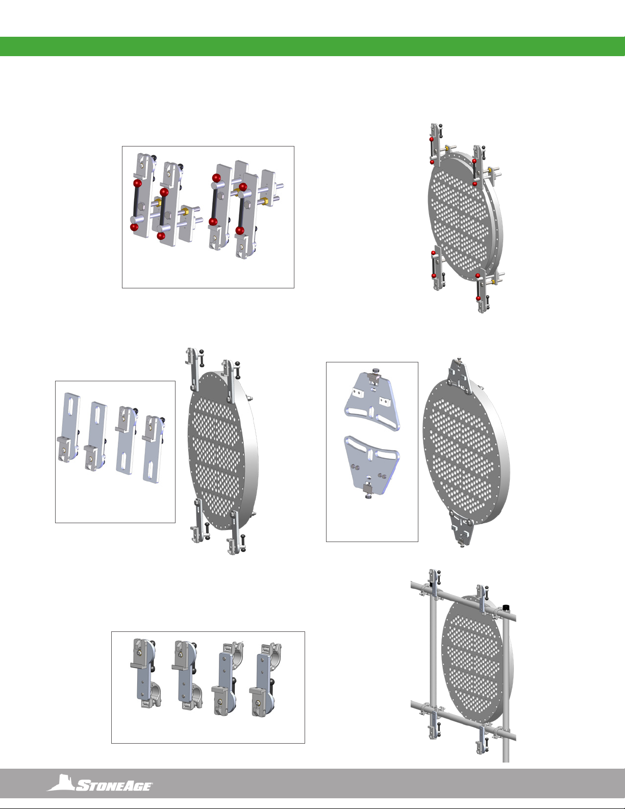
LIGHTWEIGHT POSITIONER STEP BY STEP SET-UP
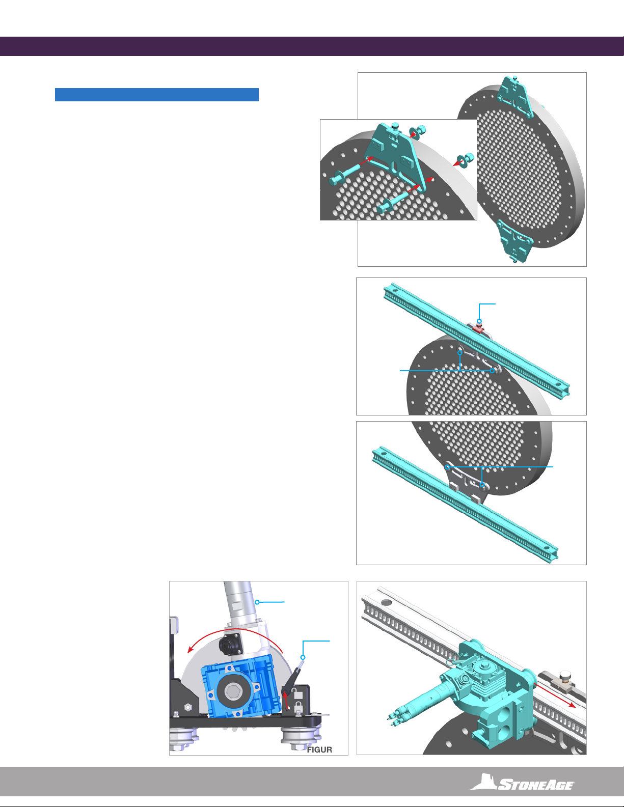
1. Mount the appropriate frame Positioner Clamps to
the tube bundle as shown in Figure 1. (Shown with
Plate Clamps) Positioner Clamps should be Parallel to
the direction of the tube rows. (Figure 1)
2. Loosen the Rail Clamp Tensioner on the top
Positioner Clamp and insert the Top Rail (slots
facing out) into the upper rail clamps. Tighten the Rail
Clamp Tensioner securing the rail to the Positioner
Clamp. Check Rail Clamp bolts to ensure they are
secured to the tube bundle ange. (Figure 2)
3. Loosen the Rail Clamp Tensioner on the bottom
Positioner Clamp and insert the Lower Rail into the
lower rail clamps. It is not critical that this rail is aligned
as precisely as the top rail, but it should be close to
parallel with the top rail for best performance. Tighten
the Rail Clamp Tensioner securing the rail to the
Positioner Clamp. Check Rail Clamp bolts to ensure
they are secured to the tube bundle ange. (Figure 3)
4. Remove the Quick Release Pin from the locked
position, pull back on the air motor to lift the gear, and
insert the Quick Release
Pin into the unlocked
position. This will allow the
Horizontal Drive Carriage
to slide onto the rail without
pneumatic power. Center
the carriage on the top rail,
pull out the Quick Release
Pin, let the gear drop into
place and verify the gear
is engaging the slotted rail
correctly. Replace the Quick
Release Pin into the locked
postion. (Figures 4 & 5)
LIGHTWEIGHT POSITIONER SET-UP
FIGURE 1
FIGURE 5
LIGHTWEIGHT POSITIONER SET-UP
FIGURE 2
Rail Clamp
Tensioner
CHECK
FIGURE 3
CHECK
FIGURE 4
UNLOCK
Quick Release
Pin
Gear
LOCK
Air Motor
NOTICE
Heat exchanger tube bundle face, shown for
graphic representation only. Not included in
assembly

12 866-795-1586 • WWW.STONEAGETOOLS.COM
5. Angle the Idler Carriage as shown to allow the
Idler Carriage to engage with the lower rail properly.
Rotate it back to the vertical position and slide it
towards the lower Rail Clamp. (Figure 6)
6. Loosen the Rail Clamp Handle on the Horizontal
Drive.Align the Idler Carriage on the lower rail so
the Vertical Rail can slide into it. Slide the Vertical
Rail with (slots facing out) down through the
Horizontal Drive clamp and between the rollers
on the idler carriage. Adjust the position of the
vertical rail as required and secure the rail in place
by tightening the Rail Clamp Handle on the
Horizontal Drive. (Figure 7)
7. Remove the Quick Release Pin from the locked
position, pull back on the air motor to lift the
gear, and insert the Quick Release Pin into the
unlocked position. This will allow the Vertical
Drive Carriage to slide onto the rail without
pneumatic power. Center the carriage on the
vertical rail, pull out the Quick Release Pin, let
the gear drop into place and verify the gear is
engaging the slotted rail correctly. Replace the
Quick Release Pin into the locked position.
(Figures 8 & 9)
8. Loosen the handles on the four Rail Stops and
slide one onto both ends of the top horizontal rail
and both ends of the vertical rail. Rotate all the
handles so they face away from Horizontal and
Vertical Drives (as shown) and ensure that they are
securely fastened. (Figure 10)
LIGHTWEIGHT POSITIONER SET-UP
FIGURE 9
FIGURE 6
FIGURE 7
Rail
Clamp
Handle
Rail
Scraper
FIGURE 10
UNLOCK
Quick Release
Pin
Air Motor
Gear
LOCK
FIGURE 8
CAUTION
Verify the Positioner Clamps and Rail Clamps are
securely fastened and both drive carriages are
securely engaged and the pinned in the locked
position.
Never unlock the vertical drive once the guide
assembly and tractor are installed, as it may result
in the carriage sliping down the vertical rail and
may cause damage and/or injury.
WARNING
Failure to secure the Rail Clamps could result in
the carriages driving off the rails. This will create a
hazardous situation which, if not avoided, could
result in death or serious injury
TECH TIP:
The rail scraper is spring loaded to t closely against
the rail to remove debris ahead of the idler roller.
Pulling up on the rail scraper or tilting the idler carriage
during installation will increase clearance and simplify
installation.

13
866-795-1586 • WWW.STONEAGETOOLS.COM
POWER HUB
VERTICAL
DRIVE
HORIZONTAL
DRIVE
90° ELECTRIC
CABLE END
90° ELECTRIC
CABLE END
LIGHTWEIGHT POSITIONER CONNECTIONS TO THE POWER HUB
CONTROL LINE CONNECTIONS
1. Remove the dust caps from all ttings of the Horizontal and
Vertical Drives.
2. Connect control lines to the front of the Power Hub
• Two Straight Electric Cable Ends ( , )
• Two 8mm diameter tubing for the Horizontal Drive ( )
• Two 8mm diameter tubing for the Vertical Drive. ( )
3. Blow out all control lines. Use of dirty or contaminated
pneumatic hoses will cause component damage and
malfunction
4. Connect control lines to the Horizontal Drive
• Connect the two 8mm diameter tubing from the Power Hub
( ) to the corresponding color coded ttings on the
Horizontal Drive.
• Connect the 90Pot Plug from the Power Hub ( ) to
the resceptacle on the sensor.
5. Connect control lines to the Vertical Drive
• Connect the two 8mm diameter tubing from the Power Hub
( ) to the corresponding color coded ttings on the
Vertical Drive.
• Connect the 90Pot Plug from the Power Hub ( ) to the
resceptacle on the sensor.
Straight Electric Cable End
and (2) 8mm diameter tubing 90° Electric Cable End and
(2) 8mm diameter tubing
CONTROL LINE ENDS
14 866-795-1586 • WWW.STONEAGETOOLS.COM
MAINTENANCE
SHOTGUN MOUNT INSTALLATION
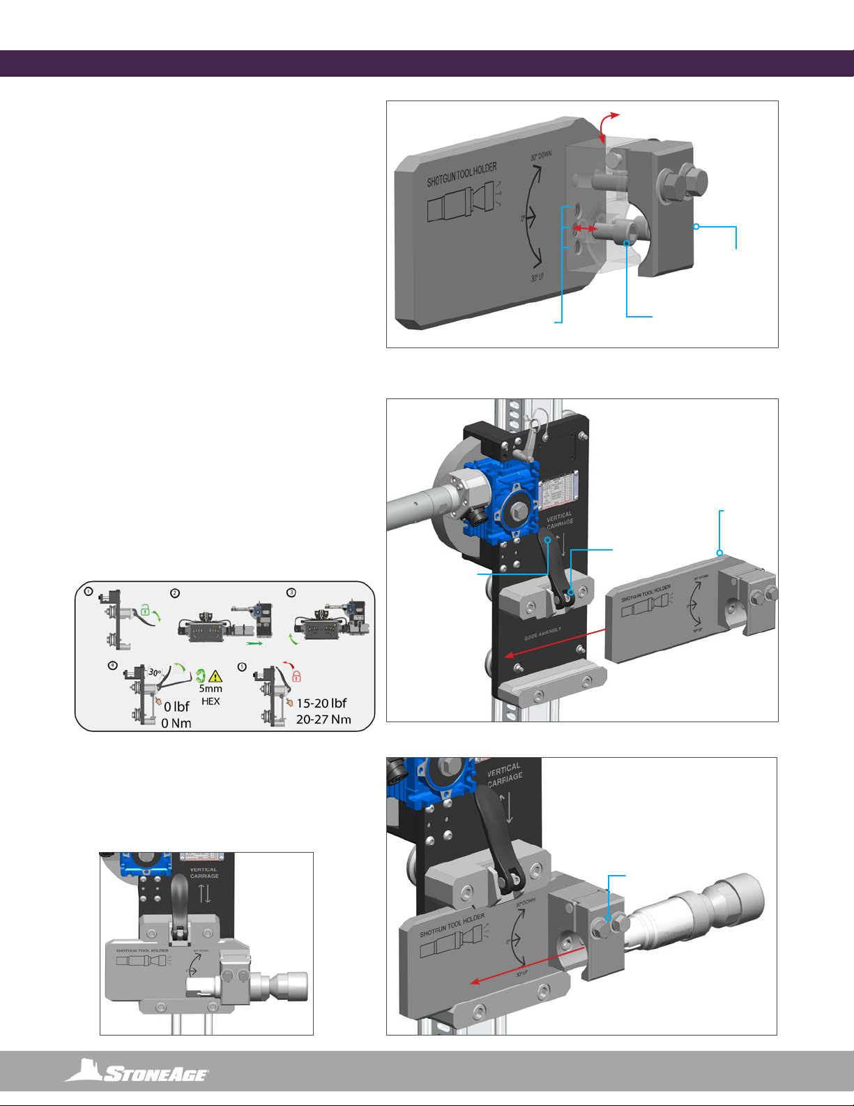
INSTALL SHOTGUN MOUNT
(FOR USE WITH BARRACUDA OR SPITFIRE TOOL)
1. Set the desired Clamp Angle.
• The Clamp Assembly on the Shotgun Mount can
be rotated 30° Up or Down by removing the two
SHCS Screws with a 5/16” Allen Key, rotating the
Clamp into the desired position, and fastening the
Screws in the desired location.
• Make sure these screws are tightened
before operation.
2. Install Shotgun Mount onto the Vertical Carriage.
• Pull to open the Clamp Handle on the Vertical
Carriage and slide the Shotgun Mount in back to
front.
• The mount will stop when it reaches the chamfers
at the front. This is a safety feature.
• Lock the Clamp Handle in place when the mount
is in position.
• If the Clamp Handle feels too loose or too tight, it
can be adjusted with a 5mm Allen Key. Follow the
instructions on the decal on the Vertical Drive.
3. Fasten the Shotgun tool in the Clamp.
• Loosen the two Hex Bolts on the Clamp with a
9/16” Hex Wrench.
• Slide the tool in back to front and securely
tighten the Hex Bolts.
5/16” ALLEN
KEY
MOUNTING
POSITIONS
TENSION
ADJUSTABLE
WITH 5mm
ALLEN KEY
CHAMFER
STOP
PULL OPEN /
PUSH CLOSED
9/16” HEX
INSTALLED
CLAMP
ASSEMBLY
15
866-795-1586 • WWW.STONEAGETOOLS.COM
Contact StoneAge for Safety Data Sheets for material usage, a complete list of spare part numbers, and service instructions for the
Lightweight Positioner.
MAINTENANCE
Return the plugs into all push connect ttings to keep water away from the connectors during cleaning. Use mild soapy water to clean the
machine in order to remove corrosive materials. Before storing the unit, use compressed air to lightly blow off debris and moisture. Apply a
small amount of air tool oil directly into the Horizontal and Vertical Drive ttings. Then, briey operate the controls at slow speed for a short
duration in each direction to coat the interior parts of the motor. Install the dust caps onto all ttings to keep moisture and dirt out.
DO NOT SPRAY WATER DIRECTLY AT OR SUBMERGE THE AIR MOTOR BREATHER PORTS OR ELECTRONIC COMPONENTS.
MAKE SURE ALL DUST CAPS ARE IN PLACE AND ELECTRICAL SENSOR CONNECTIONS ARE TIGHT PRIOR TO CLEANING.
The Lightweight POSITIONER (LWPS-100-X), can be broken down into smaller components that should be stored in a clean and dry area.
Maintenance Item Frequency Maintenance Required
Forward, reverse, and clamp ttings Before each use Inspect threads for wear or damage.
Carriage rollers Every 100 Hours of use Lubricate Zerks on all Carriage Rollers using any multipurpose
NLGI 2 grease.
Vertical and Horizontal Rails As Needed Inspect for wear that would allow Carriage Rollers to slip off.
Replace Rail as needed.
Quick Release Handles When loose or too tight 5mm hex to tighten. When it’s set correctly it should take 15-
20lbs of force to close the lever
PARTS DIAGRAM
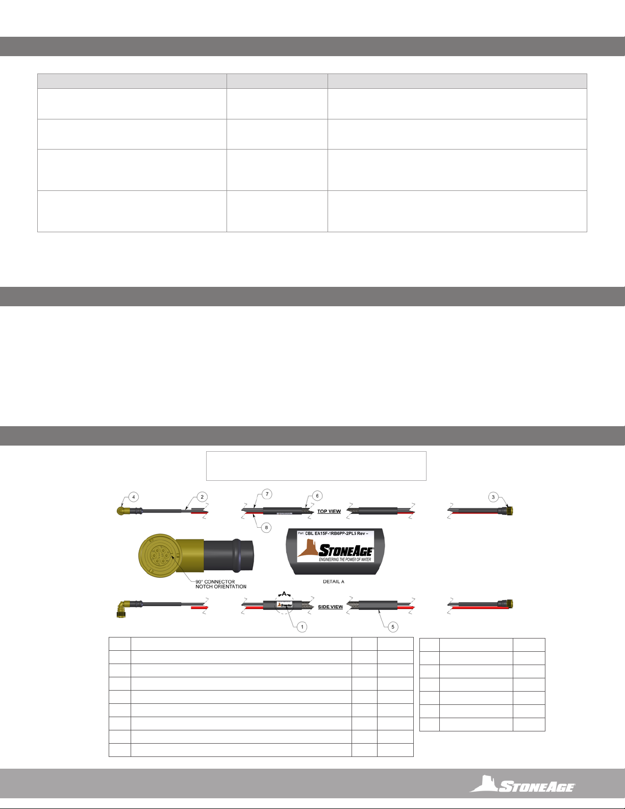
STORAGE, TRANSPORTATION, AND HANDLING
LIGHTWEIGHT POSITIONER
(CBL EA15F-1RB6PP-2LPL5)
POSITIONER CONTROL LINE ASSEMBLY
# PART NUMBER QTY OAL EACH
1 CBL EA15F-1RB6PP-2PL6.1 LABEL 1
2 CBL EA15F.1 WIRE, 1X4 PAIR, 24 (7/32_ AWG COPPER ALLOY, .011” POLYPLEFIN 1 15’-0”
3 EE CN-RB-PF6PS-14S-0001 PLUG, POT AND HEATSHRINK ENDBELL 1
4 EE CN-RB-PF6PS-14S-90-0001 PLUG, 90 DEG POT AND HEATSHRINK ENDBELL 1
5 GPHS 1100-OLE-A-BK HEAT SHRINK, 1.1” ID , BLACK 2 5”
6 GPSL 0750-NYL-G-BK HOSE BUNDLE SLEEVE 1 11’-4”
7 GPTB 8MM6-PUR95A-BK 8MM OD X 6MM ID URETHANE TUBING, BLACK 1 14’-2”
8 GPTB 8MM6-PUR95A-RD 8MM OD X 6MM ID URETHANE TUBING, RED 1 14’-2”
PIN WIRE
A BROWN / BROWN WHITE 12V
BGREEN WHITE 485-B
C GREEN 485-A
D BLUE / BLUE WHITE GND
E ORANGE SFT-A
FORANGE WHITE SFT-B
16 866-795-1586 • WWW.STONEAGETOOLS.COM
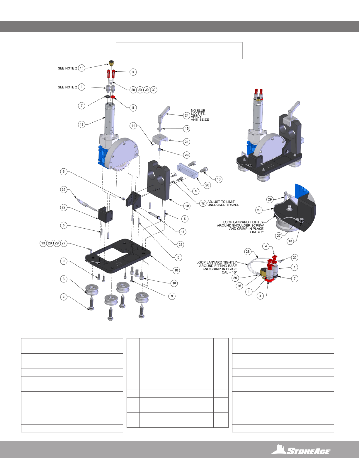
LIGHTWEIGHT POSITIONER ASSEMBLY
(LWPS-100-X)
# PART NUMBER QTY
1 BU 002-6-001 2.5” BOX RAIL EXTRUSION, SLOTTED 3
2 LWPS-100 ASSEMBLY, LWP SENTINEL NO RAILS 1
3 PL 160 WARNING PINCH POINT 1.25 X 3.0 DECAL 12
PARTS DIAGRAM
17
866-795-1586 • WWW.STONEAGETOOLS.COM
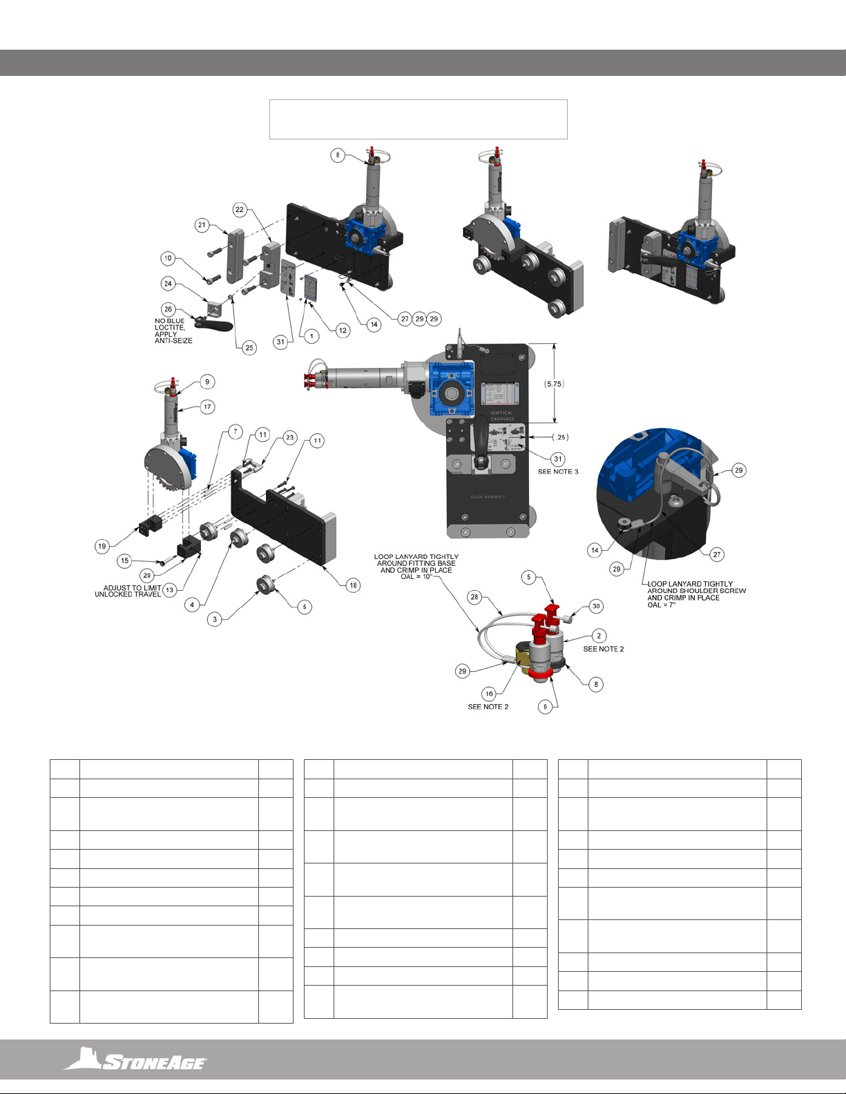
LIGHTWEIGHT POSITIONER (LWPS 140)
HORIZONTAL POSITIONER
NOTE:
1. APPLY BLUE LOCTITE (242 OR EQUIVALENT) TO THREAD OF ALL
HARDWARE, EXCEPT IF NOTED.
2. APPLY LOCTITE THREAD SEALANT (567 OR EQUIVALENT) AND/OR
TEFLON TAPE TO THREADS OF ALL PIPE FITTINGS.
PARTS DIAGRAM
# PART NUMBER QTY
1 ABXS 277 FTG, ADAPTER P2M PL5 EISELE 2
2BR 051-1.5-0 AXLE-ZERK 4
3 BR 055-SS ROLLER ASSY 4
4 CB 499 FTG, STEM PLUG PL5 MODIFIED 2
5 GDP 3M5-26 PIN, DOWEL M5 x 26 SS 6
6 GN 3M6-1.0-L NUT, NYLOK M6x1.0 SS 1
7 GP 014-BK ID WASHER, RUBBER, EXTRA
SMALL, BLACK
1
8 GP 014-R ID WASHER, RUBBER, EXTRA
SMALL, RED
1
9 GS 3M6-18-1.0 SHCS M6x1.0 x 18 SS 6
10 GS 3M10-20-1.5 SHCS M10x1.5 x 20 SS 5
11 GSP 3M3-10 SLOTTED SPRING PIN M3 X
10 SS
1
12 GSS 3M6-1.0-10CU SET SCREW, CUP PT
M6x1.0 x 10 SS
1
13 GSSH M5-4-SS SHOULDER SCREW M5 X
4 SS
1
14 GSSH M8-40-SS SHOULDER SCREW M8 X
40 SS
1
15 GW 525-F WASHER, FLAT .25 1
16 LWP 557 FTG, EXHAUST PROTECTOR P2M 1
17 LWPS 110 ASSY, GEAR DRIVE 1
18 LWPS 141 PLATE, HORIZONTAL CARRIAGE 1
19 LWPS 143 PLATE, RAIL BASE 1
20 LWPS 144 CLAMP, RAIL 1
21 LWPS 145 JAW, ADJUSTABLE CLAMP 1
22 LWPS 148 MOUNT, HORIZONTAL GEAR LEFT 1
23 LWPS 149 MOUNT, HORIZONTAL GEAR RIGHT 1
24 LWPS 151 LEVER, HAND SS 1
25 LWPS 152 PIN, QUICK-RELEASE .25 X 1.75 1
26 PROP 335 SPRING, COMPRESSION 1
27 SRT 209.1.1 WIRE ROPE FOR LWPS 140 (CUT
TO 7IN)
1
28 SRT 209.1.1 WIRE ROPE FOR LWPS AIR
MOTOR (CUT TO 10IN)
1
29 SRT 209.1.3 ALUMINUM SLEEVE 3
30 SRT 209.1.4 ALUMINUM STOP SLEEVE 2
18 866-795-1586 • WWW.STONEAGETOOLS.COM
NOTES:
1. APPLY BLUE LOCTITE (242 OR EQUIVALENT) TO THREADS OF ALL HARDWARE,
EXCEPT IF NOTED.
2. APPLY LOCTITE THREAD SEALANT (567 OR EQUIVALENT) AND / OR TEFLON TAPE
TO THREADS OF ALL PIPE FITTINGS.
3. CLEAN SURFACE WITH ISOPROPYL ALCOHOL BEFORE INSTALLING DECAL. LOCATE
APPROX. WHERE SHOWN.
LIGHTWEIGHT POSITIONER (LWPS 160)
VERTICAL POSITIONER
PARTS DIAGRAM
# PART NUMBER QTY
1 ABX 139 COLLET REFERENCE PLATE 1
2 ABXS 277 FTG, ADAPTER P2M PL5
EISELE
2
3BR 051-1.5-0 AXLE-ZERK 3
4BR 052-1.5 AXLE-ZERK 1
5 BR 055-SS ROLLER ASSY 4
6 CB 499 FTG, STEM PLUG PL5 MODIFIED 2
7 GDP 3M5-26 PIN, DOWEL M5 X 26 SS 4
8 GP 014-BK ID WASHER, RUBBER, EXTRA
SMALL, BLACK
1
9 GP 014-R ID WASHER, RUBBER, EXTRA
SMALL, RED
1
10 GS 3M10-40-1.5 SHCS M10X1.5 X 40
SS
4
11 GSB 3M6-25-1.0 BHCS M6X1.0 X 25 SS 6
12 GSB 313-0075 BHCS 6-32 X .19 SS 4
13 GSS 3M6-1.0-10CU SET SCREW, CUP PT
M6X1.0 X 10 SS
1
14 GSSH M5-4-SS SHOULDER SCREW M5
X 4 SS
1
15 GSSH M8-40-SS SHOULDER SCREW M8
X 40 SS
1
16 LWP 557 FTG, EXHAUST PROTECTOR
P2M
1
17 LWPS 110 ASSY, GEAR DRIVE 1
18 LWPS 161 PLATE, VERTICAL CARRIAGE 1
19 LWPS 163 MOUNT, VERTICAL GEAR LEFT 1
20 LWPS 164 MOUNT, VERTICAL GEAR
RIGHT
1
21 LWPS 166 CLAMP, LOWER RAIL 1
22 LWPS 167 CLAMP, UPPER RAIL 1
23 LWPS 171 PIN, QUICK-RELEASE
.25X2.75
1
24 PROP 334 TAB, CLAMP 1
25 PROP 335 SPRING, COMPRESSION 1
26 PROP 336 HANDLE ASSY 1
27 SRT 209.1.1 WIRE ROPE FOR LWPS 160
(CUT TO 7IN)
1
28 SRT 209.1.1 WIRE ROPE FOR LWPS AIR
MOTOR (CUT TO 10IN)
1
29 SRT 209.1.3 ALUMINUM SLEEVE 3
30 SRT 209.1.4 ALUMINUM STOP SLEEVE 2
31 PL 211 LWPS CLAMP DECAL 1
19
866-795-1586 • WWW.STONEAGETOOLS.COM
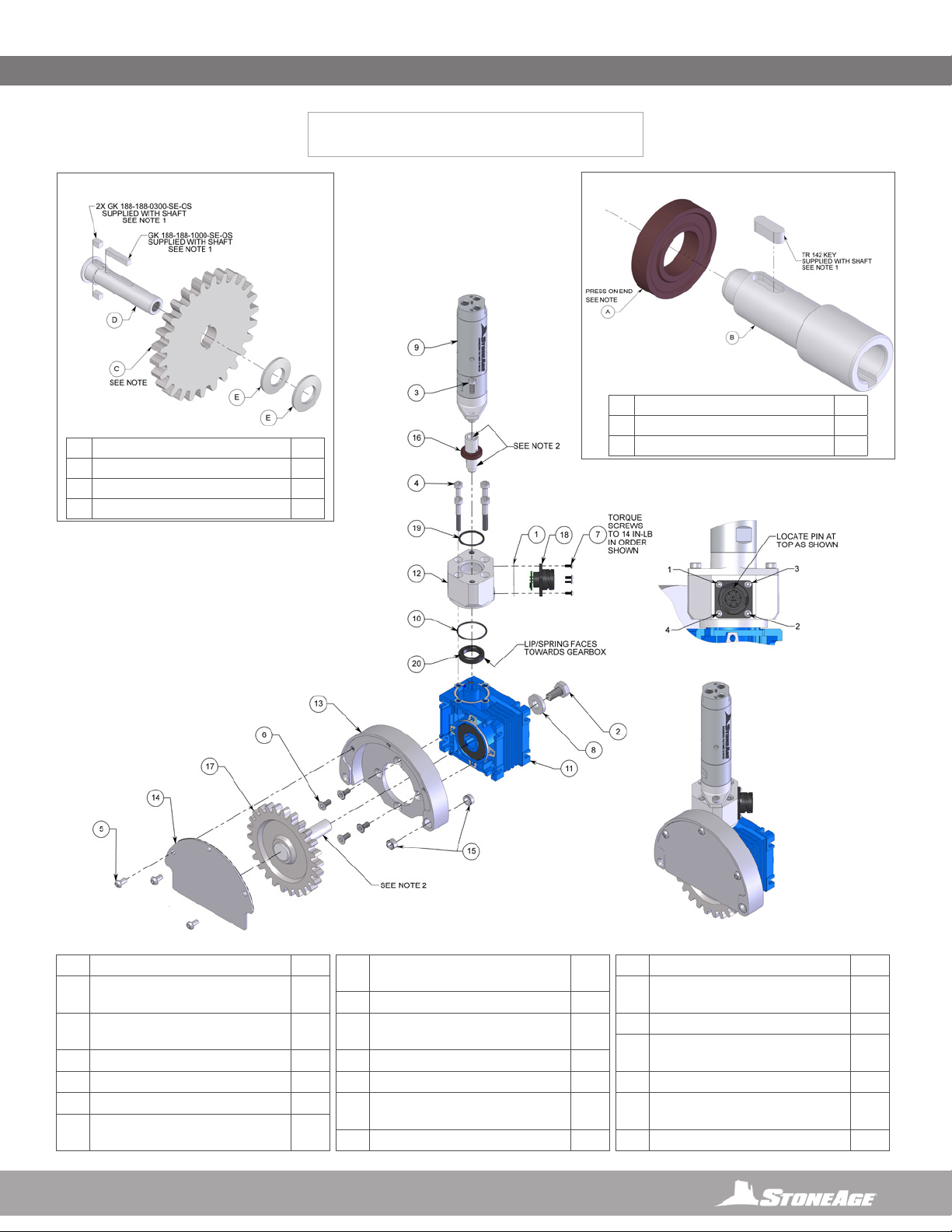
LIGHTWEIGHT POSITIONER (LWPS 110)
GEAR DRIVE ASSEMBLY
NOTE:
1. APPLY BLUE LOCTITE (242 OR
EQUIVALENT) OR EQUIVALENT TO
THREADS OF ALL HARDWARE,
EXCEPT WHERE NOTED.
2. APPLY SILVER BOSTIK NEVER SEEZ
(OR EQUIVALENT) AS NOTED.
# PART NUMBER QTY
1 EE CN-RB-G-14S-F-AX GASKET,
CONNECTOR
1
2 GB 3M10-20-1.25 BOLT, HEX M10x1.25
x 20 SS
1
3 GS 3M5-14-0.8 SHCS M5x0.8 x14 SS 2
4 GS 3M6-40-1.0 SHCS M6x1.0 x 40 SS 4
5 GSB 3M6-12-1.0 BHCS M6x1.0 x 12 SS 3
6 GSF 3M6-14-1.00 FHCS M6x1.00 x
14 SS
4
7 GTB 3M3-8-0.5 BHTS M3x0.5 x 8 Torx
SS
4
8 GW 3M10-F WASHER, FLAT M10x4mm 1
9 LWP 520-001 AIR MOTOR, SS, W/
FLANGE, LUBE FREE
1
10 LWP 538 O-RING 1
11 LWP 550 MOTOVARIO GEARBOX 1
12 LWPS 111 HUB, ENCODER MOTOR
MOUNT
1
13 LWPS 112 PLATE, DRIVE SPROCKET 1
14 LWPS 113 COVER, GEAR 1
15 LWPS 114 SLEEVE BEARING, OIL-
IMPREGNATED
2
16 LWPS 115 ASSY, STEP SHAFT 1
17 LWPS 120 ASSY, SHAFT KEYED
BELLEVILLE
1
18 LWPS 130 ASSY, LWPS SENSOR BOARD 1
19 LWPS 133 O-RING, DOUBLE SEAL
X-PROFILE
1
20 SL 010 SEAL 1
* APPLY LOCTITE RETAINING COMPOUND (680 OR
EQUIVALENT) TO COMPONENTS AS NOTED. BE SURE AND SET
MAGNET BEFORE KEY. BE SURE TO SET KEY AND MAGNET
COMPLETELY AND SECURELY WHILE LETTING LOCTITE CURE
FOR 5 HRS. WIPE EXCESS LOCTITE (ESPECIALLY SHAFT).
# PART NUMBERS QTY.
A EE MG-0001 MULTIPOLE RING 1
B LWPS 116 STEP SHAFT 1
LWPS 115 STEP SHAFT ASSEMBLY
*
*
# PART NUMBERS QTY.
C LWPS 121 GEAR, SPUR SS 3.25 CBORE 1
D LWPS 122 SHAFT, KEYED BELLEVILLE 1
E LWPS 123 WASHER, BELLEVILLE .625 X .098 2
LWPS 120 SHAFT KEYED BELLEVILLE ASSEMBLY
*
PARTS DIAGRAM

20 866-795-1586 • WWW.STONEAGETOOLS.COM
LIGHTWEIGHT POSITIONER (LWPS 180)
IDLER CARRIAGE ASSEMBLY
LIGHTWEIGHT POSITIONER (BU 152)
RAIL STOP ASSEMBLY
# PART NUMBER QTY.
1 BU 149 PLATE, RAIL STOP 1
2 BR 060 RAIL CLAMP 1
3 GB 537-05 BOLT, HEX .37-16 X 1.25 1
4 BU 151 HANDLE 1
# PART NUMBER QTY
1BR 051-1.5-0 AXLE-ZERK 3
2 BR 055-SS ROLLER ASSY 3
3 GB 3M10-30-1.5 BOLT, HEX M10x1.5 X 30 SS 2
4 GS 3M10-20-1.5 SHCS M10x1.5 x 20 SS 4
5 GSSH M8-12-SS SHOULDER SCREW M8 X 12 SS 1
6 LWPS 181 PLATE, IDLER CARRIAGE 1
7 LWPS 182 BLOCK, SPACER 1
8 LWPS 183 PLATE, GUIDE 1
9 LWPS 185 SCRAPER, RAIL 1
10 LWPS 186 STUD, VERTICAL RAIL GUIDE 2
11 LWPS 188 SPRING, WAVE 1
PARTS DIAGRAM
Table of contents
Other StoneAge Valve Positioner manuals

Popular Valve Positioner manuals by other brands


Emerson
Emerson Fisher 3610J Errata sheet

SMC Networks
SMC Networks IP6000 Installation and maintenance manual

Samson
Samson FOUNDATION 3730-5 Mounting and operating instructions

ABB
ABB PositionMaster EDP300 Commissioning Instruction

Burkert
Burkert 8791 REV.2 operating instructions

Proval
Proval A236 Series Installation, operation and maintenance manual


