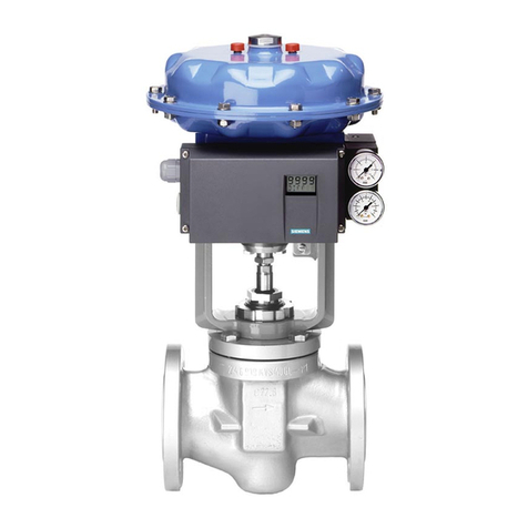
Proval A236 Series User manual

PROVAL A236 Series
Smart Valve Positioners
Installation, Operation and Maintenance Manual

1
1 INFORMATION FOR THE OPERATOR.......................................................................................................3
1.1 CLASSIFICATION OF SAFETY RELATED NOTICES...........................................................................3
1.2 SAFEY AND CAUTIONS.......................................................................................................................... 4
1.3 USE AS INTENDED...................................................................................................................................4
1.4 INSTALL AND MAINTAIN OPERATION.................................................................................................. 5
1.5 LIST OF DELIVERY......................................................................................................................................5
2 SUMMARY.........................................................................................................................................................5
2.1 FUNCTIONS...................................................................................................................................................6
2.2 SPECIALTY....................................................................................................................................................6
2.3 INTEGRATED LIGHTNING PROTECTION CIRCUIT............................................................................ 7
3TECHNICAL DATA........................................................................................................................................... 8
4INSTALLATION................................................................................................................................................. 9
4.1 DIMENSIONS.................................................................................................................................................9
4.2 INSTALLATION.......................................................................................................................................... 9
5OPERATION.................................................................................................................................................... 20
5.1 INTERFACE DESCRIPTION.....................................................................................................................20
5.1.1 DISPLAY................................................................................................................................................... 20
5.1.2 BUTTONS................................................................................................................................................. 20
5.2 CONFIGURATION MODE......................................................................................................................... 21
5.2.1 ENTERING CONFIGURATION MODE................................................................................................ 21
5.2.2 CHOOSING A PARAMETER FOR CONFIGURATION.................................................................... 21
5.2.3 CHANGING A PARAMETER.................................................................................................................22
5.2.4 RESET USER PARAMETERS.............................................................................................................. 23
5.2.5 EXITING CONFIGURE MODE.............................................................................................................. 23
5.3 INITIALIZATION....................................................................................................................................... 23
5.3.1 CHECK BEFORE INITIALIZATION......................................................................................................23
5.3.2 AUTO TUNING......................................................................................................................................... 24
5.3.3 MANUAL TUNING................................................................................................................................... 25
5.4 DIAGNOSIS MODE.................................................................................................................................... 26
5.4.1 ENTERING DIAGNOSIS MODE........................................................................................................... 26
5.4.2 EXITING THE DIAGNOSIS MODE.......................................................................................................26
5.4.3 THE DIAGNOSTIC PARAMETER........................................................................................................ 26
5.5 ALARM.......................................................................................................................................................27
5.5.1 ZERO POINT OF POSITION SENSOR TOO LOW........................................................................... 27
5.5.2 SPAN POINT OF POSITION SENSOR TOO HIGH...........................................................................27
5.5.3 INITIALIZATION ERROR....................................................................................................................... 27
5.5.4 MEASUREMENT SPAN IS INSUFFICIENT....................................................................................... 27
5.5.5 USER CHARACTERISTICS SETTING ERROR.................................................................................28
5.5.6 FEEDBACK OVER LIMITS.................................................................................................................... 28

2
5.5.7 INPUT CURRENT OUT OF WORK RANGE...................................................................................... 28
5.5.8 ACTUATOR ERROR............................................................................................................................... 28
6USER PARAMETER.......................................................................................................................................29
6.1 PARAMETER LIST..................................................................................................................................... 29
6.2 PARAMETERS............................................................................................................................................ 31
7FAULT AND MAINTENANCE....................................................................................................................... 38
7.1 TROUBLE SHOOTING...............................................................................................................................38
7.2 MAINTENANCE........................................................................................................................................ 39
8TRANSPORTATION AND STORAGE.........................................................................................................39
9ORDERING INFORMATION......................................................................................................................... 40
9.1 THE DETAIL PRODUCT MODELS IS IN THE FOLLOWING........................................................... 40
9.2 FEEDBACK CONNECTION................................................................................................................... 41

3
1 Information for the Operator
Please read this manual carefully before starting work!
1.1 Classification of Safety Related Notices
Ensure that you are safe in installing, commissioning and maintaining this instrument. Please pay
attention to the warning and notice texts.
WARNING
Potentially hazardous situation!
Non-observance could result in serious injury!
NOTICE
Hazardous situation!
Non-observance may result in minor or moderate injury!
i
NOTE
Important information in order to understand the machine for optimized
operation

4
1.2 Safeyand Cautions
i
NOTE
1. The design of this equipment meets the advanced safety requirementsand it
is safe and effective when the factory is tested out of the factory
2. This equipment is complied with the relevant rules and standards
3. The equipment manufacturer reserves the right to modify technical
parameters without prior notice
4. The permitted storage transport and operating temperature must be
observed
5. The equipment must be connected in accordance with the connection
diagram in the manual
6. The information contained in the nameplate wire connection diagram and
warning icons attached to the equipment must be followed
7. There are corresponding marks on the nameplates of equipment used in
hazardous areas. When operating equipment in a hazardous area, the relevant rules
must be complied with. The installation specifications, connection parameters, and
safety instructions provided in the Ex flameproof document must be complied with.
1.3 Use as intended
i
NOTE
1. The use may constitute a risk to life and limb of the user of third parties,or
cause damage to the machine and to other material property in the event that
use as not intended this is not allowed, .
2. The manufacturer will not responsible for damage caused by improper
operation or used as not intended.

5
1.4Install and Maintain Operation
i
NOTE
1. Installation, commissioning, operation, maintenance and repair of the
instrument requires special knowledge and should be performed only by
qualified personnel.
2. For installing this instrument, the operator must read the user's manual
and comply with the rules.
3. When the instrument is installed, it should be in the state of power off and
no external load is overstressed.
4. The instrument must not be modified or repaired unless the user is
according to the manual.
5. Repairs that are not described in the supplied operation manual may only
be carried out directly by the manufacturer or by the service organization.
6. If the welding operation is carried out near the equipment, the grounding
of the welding equipment must not be carried out through this equipment.
1.5List of Delivery
A236 smart valve positioner.
User's manual
Ordered spare partsOptional
2Summary
A236 smart valve positioner is a two-wire system instrument. The positioner is a control accessory
of pneumatic valve. It is widely used in automatic control systems of petroleum,chemical,
electricity, metallurgy, paper and pulp industry and other fields.
A236 smart valve positioner accepts the 4~20mA valve setting analog signal from the control
system.
This valve setting value will be converted by an analog to digital converter (ADC) to digital signal then
input to CPU. At the same time, instrument gets the actual valve position from location sensors. The two
signals are compared by the instrument software so as to control the intake and exhaust of the
pneumatic actuator, and drive the valve to reach setpoint (refer to Figure2-1)
A236 smart valve positioned is based on microprocessor technology. It can overcome friction and
the imbalance power on the control valve well, and improve the response speed of control valve, which
makes the position set rapidly and accurately. It is not only able to completely substitute conventional
valve positioner, but also is able to directly access HART network, exchanging information between

6
control system and positioner.
A236 smart valve positioner is complied with the IEC60079-0:2017Explosive atmospheres - Part
0:Equipment - General requirements and Explosive atmospheres - Part 11: Equipment protection
by
intrinsic safety "i". A236 smart valve positioner is complied with Electrical apparatus for use in
the
presence of combustible dust - Part 11: Protection by intrinsic safety 'iD'.
Fig2-1 A236 Valve Positioner Principle
2.1 Functions
Self-adaption function: automatically set the Zero and Span of control valve, and optimize the control
parameters to improve the control precision.
Configuration function: valve characteristic curve, action mode, dead band, stroke range, shut-off
value and alarm events, .
Self-diagnosis function: show the value of setpoint current, travel time, and dead band.
Fault mode function: fail safe (function open/close) or fail freeze (function hold).
Communication function: HART communication protocol.
Feedback function: 4~20mADC valve position feedback signal, switch valve feedback signal.
2.2 Specialty
Positioning precision: 0.5%F.S.
The operation does not need to open the cover.
Simple and compact design, modular construction
Automatic initialization, automatic diagnosis, dynamic setting of valve characteristic curve
Less components, better anti-vibration performance

7
Local or remote parameters configuration
Less power and air consumption, less operation cost for customers.
Two-wire supply in 4-20mA standard
The integrated lightning protection module can be selected to reduce the damage probability of the
locator due to the surge of lightning
2.3 Integrated lightning protection circuit
With the development of technologies, the smart valve positioner becomes more intelligent with
communication bus technology. Therefore, it is inevitable to use a number of highly integrated
components, which will depress the performance of overcoming overvoltage, over current and anti-surge.
When lightning coming, these components can be easily damaged, which will lead to positioner failure. If
the control valve is use for critical process control or on high reliability position, the lightning may cause
production out of control or accident because of the sudden failure of the positioner. Normal smart valve
positioner is easy to be damaged by lightning. It is dangerous for production activities. In order to solve
this problem, A236 has surge protection function by a built-in surge discharge circuit.
i
NOTE
1. The lightning protection function is an optional function;
2. It must be grounded according to relevant standards, when installing the
lightning protection positioner.

8
3 Technical Data
Pneumatic
Supply Air Pressure 0.140.7 MPa
Valve Leakage <0.6L / H
Air Consumption <36L / H
Air Supply
According to ISO8573-1
Size and density of particulates: Class 4
Oil concentration: Class 4
Dew point: Class 4 or 10K below operating temperature
Input/Output
Actuator Single acting, Double acting
Travel Range Linear: 10~100mm(10-20mm,1:6 transmission ratio is optional);
Rotation angle:30~105º
Input Current 4~20mADC,Minimum input current:>3.8mA,split range start and end
point adjustable
Feedback Output 420mA DC
Digital Input 1 dry contract
Digital Output Electronic switch:2 channel
Piezo Valves Switch
Time Average failure free time: >2billion
Output Characteristic Linear, 1:30, 30:1, user defined (20points)
Communication HART
Display
LCD 2×7 digitals, dimension:22×38mm
Pressure Gauge Optional, displaying the in and out pressure
Operate
Self Tuning Automatic calibrate the Zero and Span, dead band
Self Diagnose Show the value of input current , travel time, dead band, etc.
Manual 3 keys on the front panel
Precision
Dead Zone 0.1~10%adjustable
Linearity ±0.5% FS
Hysteresis 0.5% FS
Environment
Ambient Temperature
Range
General type:-(40~80)°C
Intrinsic safety: -40~+50°C(T6) /65°C(T5) /80°C(T4)
Relative Humidity 595%RH
Vibration Resistance 15150Hz@2g
IP Protection Level IP65According to customer needs
Explosion-Proof Type Exia IIC T4~T6 Ga, Exia D 20 T80/T95/T130
Appearance
Weight 2 .0 kg
Dimension 170×96×92mm
Housing Material Aluminium Die casting

9
4 Installation
4.1 Dimensions
Fig 4-1 A236 Dimensional drawing
4.2 Installation
4 2 1 General. .
Fig. 4-2 shows the positioner feedback indicator and the arrow which indicate the rotating range.
The shown position is the middle position of the rotating range. Without initialization, the LCD feedback
value should be about 50.0 and the bottom row displays NOINI. The two dotted lines are the limit
positions of the feedback rotating range in normal status. The position sensor was adjusted before out of
factory.
Fig.4-3 is the image which shows that positioner is mounted on a linear actuator with standard
feedback lever. The recommended feedback angle is from 40° to 60°on a linear actuator.
Fig. 4-4 is the image which shows that positioner is mounted on a rotary actuator with standard
feedback lever

10
Lim it 1
Lim it 2
Fig 4-2
fe ed ba ck shaft
fe ed ba ck lever
Fig 4-3
feed b ack shaft
feed b ack lever
Fig 4-4

11
4.2.2 Installation on a linear actuator
Number QTY Name Specification
1 6 Inner-hexagon head screw M8x12
2 6 Spring washer D8
3 6 Washer D8
4 1 Actuator bracket
5 1 Positioner bracket
6 2 Inner-hexagon head screw M6x12
7 2 Spring washer D6
8 2 Washer D6
9 1 Feedback bracket
10 1 Feedback lever
11 2 Screw with washer and spring washer M5 x10
Note1. Optional Modules;
2. If the threaded hole just on the left of the actuator, so the positioner bracket screw in the left of the
positioner.
1
1
1
2
2
2
33
3
54
6789
4
9
10
Fig.4-5
Installation on a linear actuator
The positioner mounting on the front of the actuator, with the adjustable connection by the feedback
lever and feedback bracket(Fig. 4-5).
The installation steps as followings:
Fix the positioner bracket (Fig. 4-5/) to the positioner with inner-hexagon head screws(Fig. 4-5/),

12
spring washers (Fig. 4-5/) and washers (Fig. 4-5/).
Fix the actuator bracket (Fig. 4-5/) to the actuator with inner-hexagon head screws(Fig. 4-5/),
spring washers (Fig. 4-5/) and washers (Fig. 4-5/).
Fix the feedback bracket (Fig. 4-5/) to the actuator with inner-hexagon head screws(Fig. 4-5/),
spring washers (Fig. 4-5/) and washers (Fig. 4-5/).
Fix the feedback lever (Fig. 4-5/) to the feedback shaft of positioner through fasten screw.
Fix the positioner to the actuator with inner-hexagon head screws(Fig. 4-5/), spring washers (Fig.
4-5/) and washers (Fig. 4-5/).
After installation, please fine-tune the position of the actuator bracket (Fig. 4-5/) and feedback
bracket(Fig. 4-5/) to make sure that the feedback lever(Fig. 4-5/) is horizontal when the valve is 50%
opened. See the solid line in Fig. 4-5.
For a linear actuator, the travel angle of the feedback lever should be from 40° to 60°. If beyond this
range, it will cause significant nonlinearity errors.
4.2.3 Installation on a rotary actuator
Item QTY Name Specification
1 4 Washer D6
2 4 Spring washer D6
3 4 Hexagon head screw M6×10
4 1 Feedback lever
5 1 Screw M4×5
6 1 Positioner bracket
7 2 Actuator bracket
8 1 Feedback bracket
9 1 Hexagon head nut M6
10 4 Hexagon head screw M5×10
11 4 Spring washer D5
12 4 Washer D5
13 4 Hexagon head screw M5×10
14 4 Spring washer D5
15 4 Washer D5

13
6
4
5
3
1
2
7
8910
11
12
13 1415
Fig.4-6 Installation on a rotary actuator

The installation steps as followings ((Fig. 4-6):
Fix the positioner bracket (Fig. 4-6/) to the positioner with hexagon head screw (Fig. 4-6/), spring
washers (Fig. 4-6/) and washers (Fig. 4-6/).
Fix the feedback lever (Fig. 4-6/) to the shaft of actuator through hexagon head nut(Fig. 4-6/).
Fix the actuator bracket (Fig.4-6/) to the actuator with hexagon head screw (Fig.4-6/10), spring
washers (Fig.4-6/ ) and washers (Fig.4-6/ )
Screw in hexagon head nut (Fig.4-6/) to feedback lever (Fig. 4-6/), screw in the feedback lever to
the actuator and fasten it with the hexagon head nut (Fig.4-6/).
Put the positioner carefully on the actuator. The pin of the feedback lever (Fig. 4-6/) should be in the
slot of the feedback lever (Fig. 4-6/). Adjust the height of the positioner, fasten the screw on the pin of
the feedback lever (Fig. 4-6/) and fix the positioner with hexagon head screw(Fig. 4-6/13), spring
washers (Fig. 4-6/14) and washers (Fig. 4-6/15). Adjust the rotate angle of the feedback lever to comply to
the requirements in §4.2.1.
i
NOTE
1Do not cover the exhaust with the mounting bracket.
2The feedback lever should comply to the requirements in §4.2.1 for the rotary
actuator.
3The feedback lever is horizontal when the valve is 50% opened
for the linear actuator.
4.3 Pneumatic Connection
Pneumatic connection is on the right side of the positioner. Positioner provides two kinds of
connection type: G1/4 or NPT 1/4 (refer to ordering data). See the specific marks on the housing and
choose correct type according to the marks.
OUT1
O U T
IN IN
O U T2
Fig 4-7Pneumatic Connection
Installation Steps:
Connect the output of the A236 smart positioner to the input of the actuator according to Fig.
4-7.

Connect the IN port of the A236 smart positioner to the air source. The compressed air must be
filtered
and regulated by the pressure release valve.
Air requirements:
1.
Air pressure must be 0.14 ~ 0.7MPa, depending on the actuator.
2.
Air supply should be clean dry air without visible oil steam, oil or other liquids.
3.
Air supply should be no significant corrosion air, steam and solvents.
4.
Size and density of particulates is Class 4,Oil concentration is Class 4.
5.
The air dew point under work pressure should be at least 10 K lower than positioner
working environment temperature.
4.4 Electrical connection
4.4.1 Basic requirements
The electrical connections should be strictly in accordance with the connection diagram, and firmly
fixed and not be loose, .
The intrinsically safe positioner must be combined with the associated equipment/intrinsic equipment
that has passed the explosion-proof certification to form an intrinsically safe explosion-proof system for
use in an explosive atmosphere. The wiring of the system must comply with the requirements of the
positioner and the associated equipment/intrinsically safe equipment, and the terminals must not be
connected incorrectly.
The standard cable connector of this product is a standard waterproof connector. The outer diameter
of the signal cable needs to be 8mm and the connector cover should be locked when installing to avoid
the IP protection level of this product. If the user introduces the cable introduction device, it must be used
locally. A cable entry device or a blocking device approved by a state-authorized inspection agency that
meets the requirements of national standards and has a casing protection rating not less than IP20 can be
used in explosive hazardous locations.
Any gas that can corrode the flameproof enclosure is prohibited around the positioner.
Operator in installing commissioning and maintaining, should comply with the manual and the
followings:
IEC 61241-11:2005, Electrical apparatus for use in the presence of combustible dust - Part 11:
Protection by intrinsic safety 'iD'
IEC 60079-19:2019 Explosive atmospheres - Part 19: Equipment repair, overhaul and reclamation
IEC 60079-14:2013 Explosive atmospheres - Part 14: Electrical installations design, selection and
erection
WARNING
Junction leakage is strictly prohibited. Use soapy water to inspect air
tightness of connection interfaces.

IEC 60079-17:2013 Explosive atmospheres - Part 17: Electrical installations inspection and
maintenance
IEC 60529-2013 Degrees of protection provided by enclosures (IP Code)
4.4.2 Connectionin Intrinsically safe version
4.4.2.1 Input electrical connection(Fig. 4-8)
Type: Loop Power Supply system Input signal: 4~20mA
The min working current: 3.8mAD.C
Input impedance: 455W @20mA (Without HART)575W @20mA (With HART)
Barrier requirement : Intrinsically safe parameter (1+ ~2-):
Uo≤28V DC
Io≤93mA
Po≤0.65W
U
i
=28V
DC
I
i
=93mA
P
i
=0.65W
C
i
=18n F
L
i
0
Non-hazardous AreaHazardous Area zone 0,1 or 2
1
3
2
4
+
-
digital input
p o sitio n e r
4~20mA DC
H A R T
Commu-
nicator
Sa fe ty b a rrie r
D C S
I,V A
E
Fig 4-8Input electrical connection
4.4.2.2 Digital output module electrical connection (Fig.4-9)
Working Voltage<15.5V DC
Output signal:
Digital feedback module Output current
Signal status "high" ≥2.1 mA
Signal status "low" ≤1.2 mA
Intrinsically safe parameter (21+ ~22-),(31+ ~32-): Barrier requirement :
Ui=15.5V DC
Ii=25mA
Pi=96.9mW
Ci≈0
Li≈0
Uo≤15.5V DC
Io≤25mA
Po≤96.9mW
Hazardous Area zone 0,1 or 2Non-hazardous Area

D C S
I,V
2K 21
22
31
32
2K
_
_
+
+
D ig ita l o u tp ut m o d ule
Sa fe ty b a rrie r
D C S
I,V
Fig.4-9
Digital output module electrical connection
4.4.2.3 Analog feedback module electrical connection (Fig.4-10)
Feedback signal type: Two-wire system,4~20mA
DC
Temperature influence≤100ppm/
Working range3.6 ~ 20.5 mA DC
Precision≤0.1%
Working voltage:12 28VDC
Intrinsically safe parameter (11+ ~12-): Barrier requirement :
Ui =28V DC
Ii=93mA
Pi=0.65W
Ci=10nF
Li≈0
Uo≤28V DC
Io≤93mA
Po≤0.65W

Hazardous Area zone 0,1 or 2Non-hazardous Area
11
2K
12
12~28V
_
_+
+
A n a lo g fe e d b a c k m o d u le
D C S
I,V
Sa fe ty b a rrie r
Fig.4-10
Analog feedback output module electronic connection
4.4.3 Connection in Non-intrinsically safe version
4.4.3.1 Input electrical connection (Fig. 4-11)
Type: Loop Power Supply system Input signal: 4~20mA
The min working current: 3.8mAD.C
Input impedance: 455W @20mA (Without HART) 575W @20mA (With HART)
1
3
2
4
+
-
digital input
p o sitio n e r
4~20mA DC
H A R T
Commu-
nicator
Sig n a l iso la to r
DCS A
E
Fig 4-11Input electrical connection
..
4.4.3.2 Digital output module electrical connection (Fig.4-12)
Working Voltage12~35V DC
Output signal:
Digital feedback module Output current
Signal status "high" ≥2.1 mA
Signal status "low" ≤1.2 mA

D C S
2K 21
22
31
32
2K
_
_
+
+
D ig ita l o u tp ut m o d ule
Sig na l iso la to r
D C S
Fig.4-12
Digital output module electrical connection
4.4.3.3 Analog feedback module electrical connection (Fig.4-13)
Feedback signal type: Two-wire system,4~20mA
DC
Temperature influence≤100ppm/
Working range3.6 ~ 20.5 mA DC
Precision≤0.1%
Working voltage:12 30VDC
11
2K
12
12~30V
_
_+
+
A n a lo g fe e d b a c k m o d u le
D C S
Sig n a l iso la to r
Fig.4-13
Analog feedback output module electronic connection
Table of contents
Popular Valve Positioner manuals by other brands

ABB
ABB PositionMaster EDP300 Operating instruction
Spirax Sarco
Spirax Sarco SP400 Installation and maintenance instructions
PI
PI UPL-120 Short instructions
GEM
GEM 1435 ePos Assembly instructions

innove
innove VP100 INSTALLATION PROCEDURE
Spirax Sarco
Spirax Sarco PP 5 Series Installation and maintenance instructions
