Ytc YT-2300 Series User manual

-1-
YTCV.1.03
-2-
-Content(H/W)-
Content 2
Manualdescription 4
Notesonsafetyandwarranty 4
Productdescription 5
Featuresandfunctions 6
Nameplatedescription 7
Orderingnumber 8
Specifications 9
Structure 10
Installation 11
Notes 11
YT-2300Ldrawing 11
YT-2300Rdrawing 12
Toolsforinstallation 13
YT-2300Linstallation 13
Example 13
InstallingYT-2300Lwithbracket 14
YT-2300Rinstallation 18
Example 18
InstallingYT-2300Rwithbracket 19
Pipingconnection 22
Note 22
Conditionsofsupplypressure 23
Conditionsofpipe 23
Pipingconnectionwithactuator 23
Singleactingactuator 23
Doubleactingactuator 24
Powerconnection 25
Notes 25
Terminalconnectionofcurrentinputsignal 25
Terminalconnectionoffeedbacksignal 26
Innerterminalconnectionforground 27
A/Mswitch 27
Variableorifice 28

-3-
-Content(S/W)-
Autocalibrationandbasicoperations 29
Buttondescription 29
RUNmode 30
FirstAutocalibration 30
Entiremodesandfunctions 31
Autocalibration(AUTOCAL) 31
Auto1calibration(AUTO1) 32
Auto2calibration(AUTO2) 33
Auto3calibration(AUTO3) 33
BIAScalibration(BIAS) 33
Velocitycalibration(V_0) 33
Manualmode(MANUAL) 34
Parametermode(PARAM) 35
Parametertypes 35
Parameteradjustment 35
Deadzone(dEAdZONE) 35
Pcontrol(KP) 36
Icontrol(KI) 37
Dcontrol(KD) 38
Handcalibrationmode(HANDCAL) 39
Handcalibrationtypes 39
Adjustmentofvalvezeroandendpoint 39
Adjustmentoftransmitterzeroandendpoint 40
Valvemode(VALVE) 42
Adjustmentofactingtype(ACT) 42
Adjustmentofcharacteristics(CHAR) 43
Adjustmentofusercharacteristics(USERSET) 43
AdjustmentofTightOpenmode(TSHUTOP) 44
AdjustmentofTightClosemode(TSHUTCL) 45
Adjustmentofsplitrange(SPLIT) 46
Viewmode(VIEW) 46
Errorandwarningcode 47
Mainsoftwaremap 49
-4-
Manualdescription
Thanksforpurchasingourproducts.
Ourproductsareproducedandinspectedunderthestrictstandards.Inordertousethe
productsappropriatelyandefficientlywerecommendthatusersreadthismanualcarefully
andfullyunderstand.
*Thismanualshouldbedeliveredtotheenduser.
*Thismanualcanbechangedwithoutpriornotice.
*Thismanual,inwholeorpart,shallnotbetranscribedorcopiedwithoutapprovalby
YTC.
*Changesofspecification,structureandcomponentsmaynotleadtotheimmediate
revisionofthismanual.
Notesonsafetyandwarranty
*BeforehandlingYT-2300,itisabsolutelyimperativethatusersreadandobservethe
safetyinstructionsinthismanualinordertoensuretheprotectionandsafetyof
operators.
*Wedonothaveresponsibilityforthedamagecausedbyusers'repairorconversionof
theitem.Iftherepairorconversionisnecessary,submitinquiries.
*Warrantyperiodismarkedonthequotationsheet,whichisfreeofchargeinprinciple.
*Forthefollowingcasessomecostshallbecharged.
-Inappropriatemaintenancebyusers
-Inappropriatetransportationandstorage
-Theproductisusedbeyondspecification.
-Inappropriateinstallation
-Uncontrollabledisastersuchasfire,earthquake,storm,flood,etc

-5-
ProductDescription
YT-2300SmartValvePositionercontrolsvalvestrokeaccuratelyaccordingtoinputsignal
of4-20mAbeinginputfromcontroller.Inaddition,highlyefficientmicroprocessingoperator
builtintheproductperformsvariousandpowerfulfunctionslikeAutocalibration,PID
control,AlarmandHartprotocol.
YT-2300RSmartPositioner
YT-2300LSmartPositioner
-6-
Featuresandfunctions
1.LCDequippedoutsideofproductmakestocheckthepositionerconditioninthefield
directly.
2.Itenduresseverevibration.
3.Itisoperatednormallyregardlessofchangeofsupplypressureduringoperation.
4.Autocalibrationmethodisverysimple.
5.Itiseasilyequippedonsmallactuatorbecauseofitssmallsize.
6.Airconsumptionissosmallthatoperatingcostinhugeplantsisdecreased.
7.Becauseitcanbeusedinlowvoltage(8.5V),thereisnolimitationincontroller.
8.Variableorificeisappliedandsoincaseofsmallactuatorthehuntingiscontrolledto
theoptimumconditionduringoperation.
9.Hartcommunicationmakestoprocessvariousinformationofvalveandpositioner.
10.Valvesystemisstablebyoutputtinganalogfeedbacksignal.
11.TheadjustmentofValvecharacteristics(Linear,Quickopen,Equalpercentage)is
available.
12.Specificflowcontrolisavailablewithsetting16pointatusers'command.
13.TightShut-CloseandShut-Opencanbesetvoluntarily.
14.PIDparameterscaneasilyadjustedinthefieldwithoutadditionalcommunicator.
15.ThepressureofAirfilterregulatorissenttoActuatordirectlywithusingA/Mswitch.
16.Splitrangesuchas4-20mA,12-20mAisavailable.
17.SettingZeroandSpanaspartialsectionisavailablebyHandCalibrationfunction.
18.Thevalvedefectiseasilycheckedbecausethevalvecanbeoperatedvoluntarily.
19.IthasIP66protectiongrade.
20.Airfilterregulatorcanbeattachedwiththeproductwithonlyonelinearnipple
withoutextrapiping.
21.BecauseofEpoxypolyesterpowdercoating,itcanbeusedforlongperiodoftimein
corrosiveair.
22.Becauseofsimpleandmodulizedinnerstructure,maintenanceisveryeasy.

-7-
NameplateDescription
Modelnumber
Productmodelnameandadditionaloptioncodes
Referthenextchapterfordetailedorderingnumber.
Protection
Protectiongradeappliedtotheproduct
IthasIP66protectiongrade.
Inputsignal
Currentinputsignalrange
DC4-20mAcurrentisused.
Ambienttemperature
Ambienttemperaturerangeforoperatingproduct
Standardambienttemperatureis-20to70.
Supplypressure
Supplypressurerangeinputtingproduct
Itissetas1.4-7kgf/(0.14-0.7MPa).㎠
Serialnumber
Thenumbersgiveneachproduct
Bytrackingthisnumbervariousinformationfortheitemcanbecollected.
YT-2300Label
-8-
Orderingnumber
YT-2300seriesusethefollowingorderingnumbers.
YT-2300 ꊲꊳꊴꊵꊶꊷ
Note1.No.4lever(100~150mm)isconnectedoneofNo.2andNo.3lever.
1.Motiontype L:Linear
R:Rotary
2.Actingtype S:Singleacting
D:Dobleacting
3.Explosionproof n:Nonexplosionproof
4.Feedbacklever
(YT-2300L)
1:10~40mm
2:20~70mm
3:50~100mm
4:100~150mm(note1)
Feedbacklever
(YT-2300R)
1:M6x40L
2:M6x63L
3:M8x40L
4:M8x63L
5:Namurstandard
5.Connectiontype 1:PT
2:NPT
6.Communication 0:None
2:Hartcommunication
7.Option 0:None
1:Positiontransmitter

-9-
Specification
Model YT-2300L YT-2300R
ActingType Single Double Single Dpuble
InputSignal 4~20mADC
MinimumCurrentSignal 3.2mA(Standard),3.8mA(HartIncluded)
SupplyPressure 1.4~7kgf/cm2(0.14~0.7MPa)
Stroke 10-150mm 60-90
Impedance Max.500Ohm/20mADC
AirConnection PT1/4,NPT1/4
GaugeConnection PT1/8,NPT1/8
ConduitEntry PF1/2(Standard),NPT1/2(Option)
Protection IP66
AmbientTemperature -30~80
Linearity ±0.5%F.S.
Hysteresis 0.5%F.S.
Sensitivity ±0.2%F.S
Repeatability 0.3%F.S.
FlowCapacity 70LPM
AirConsumption below2LPM(sup=1.4K),below3LPM(sup.=7K)
LCDTemp.Condition StorageTemp:-30~85,OperatingTemp:-10~70
OutputCharacteristic Linear,QuickOpen,EQ%,UserSet(16Point)
VibrationEffect 6G
Humidity 5-95%RHat40
Communication(Option) HARTCommunication(Non-DDL)
FeedbackSignal(Option) 4-20mA(DC10-30V)
Material AluminumDiecasting
Weight 1.5kg(3.3lb)
Painting EpoxyPolyesterePowderCoating
Color BlueorBlack
1.Basedontemperature20,absolutepressure760mmHgandrelativehumidity65%
2.Contactusfortheproductbeyondthespecification.
3.TochangeProductcolorortouseuser'sownlabelisavailable,buttheyarelimited
tothebigvolumesofquantity.Contactoursalesdept.
-10-
Structure
ThestructureofYT-2300Lisasfollows.ThatofYT-2300Risassameaslineartype
exceptfeedbacklever.
Outsidecover
Middlecover
MainPCB
PCBsupport
VariableresistancePilotrelay
MaingearVariableorifice
Mainshaft
Body
Feedbackspring
Flangenut
Feedbacklever
YT-2300Structure

-11-
Installation
Note
Whenthepositionerisinstalledwiththeactuatororreplaced,ensurethefollowings.
-Allinputsandsupplypressuretovalve,actuatorandotherinstrumentmustbeshut
down.
-Inorderentiresystemnottoshutdownthecontrolvalvemustbeseparatedfromthe
systembybypassvalveorotherequipment.
-Nopressureremainsintheactuator.
YT-2300Ldrawing
YT-2300Ldrawing
-12-
YT-2300Rdrawing
YT-2300Rdrawing
*Thebracketsforattachingontheactuatorsaremadebyusingthesedrawingsand
theyarealsousedforcheckingpiping,etc.

-13-
Toolsforinstallation
Toolsandboltsusedforassemblyare,
1.Hexagonalwrenches
2.(+)screwdriver
3.(-)screwdriver
4.Spannersforhexagonheadbolts
YT-2300Linstallation
YT-2300Lisusedforlinearmotionvalvesuchasglobevalveorgatevalveusingspring
returntypediaphragmactuatororpistonactuator.YT-2300Lconsistsofthefollowing
components.Besurethatallthecomponentsareprepared.
1.YT-2300mainbody
2.Feedbackleverandleverspring
3.Flangenut(attachedonthebottomofmainshaftofYT-2300Lbody)
4.4pcsofHexagonheadboltM8x1.25P
5.4pcsofM8platewasher
YT-2300installationexample
YT-2300Linstallationexample
-14-
InstallingYT-2300Lwithbracket
1.Firstofall,itisnecessarytomakeproperbrackettoattachonactuatoryoke.
Themostimportantthingsinmakingbracketareasfollows.
1)YT-2300Lfeedbacklevershouldbelevelat50%ofvalvestroke.(Refertono.7in
thischapter.)
2)Feedbackleverconnectionbarofactuatorclampshouldbeconnectedattheposition
thatvalvestrokeandthenumberscarvedonfeedbackleverisfitted.(Refertono.8in
thischapter.)
Ifthebracketmeetstheaboveconditions,YT-2300Lisinstalledveryeasily.
2.AssembleYT-2300Landbracketwithbolts.Usestandardboltsinboltholesonthe
backsideofYT-2300L.ThestandardofboltscrewisM8x1.25Pandotherboltstandards
areavailableasoption.Fordetails,contactoursalesdept.
InstallingYT-2300Lwithbracket
3.AfterassemblingYT-2300Landbracketwithbolts,attachitwithusingboltholesof
actuatoryoke.Butdonotattachcompletely.Theremustbesomespace.

-15-
4.InstallbarconnectedwithYT-2300Lfeedbackleverontheactuatorclamp.Theslot
lengthbetweenYT-2300Lfeedbackleveris6.5mm,sothediameterofconnectionbar
shouldbelessthan6.3mm.
Installationofactuatorclampandconnectionbar
5.Connectairfilterregulatorwiththeactuatortemporarily.Setsupplypressureofair
filterregulatorinorderthatactuatorclampispositionedat50%ofvalvestroke.
Connectionofsupplypressurepipebetweenactuatorandairfilterregulator
-16-
6.InsertconnectionbarattachedonactuatorclampintotheslotofYT-2300Lfeedback
lever.Ensurethatinsertingshouldbethefollowingpictureinordertoreducehysterisis.
Theconnectionbarinsertedcorrectlybetweenfeedbackleverandleverspring
7.CheckifYT-2300Lfeedbackleverislevelat50%ofvalvestroke.Ifnot,makeitbe
levelwithmovingbracketorfeedbacklinkbar.IfYT-2300isinstallednotbeinglevelat
50%ofvalvestroke,productlinearitybecomesworse.
Feedbackleverbeingleveledcorrectly

-17-
8.Checkvalvestroke.ThenumbersindicatingstrokearecarvedontheYT-2300L
feedbacklever.Setconnectionbarattachedonactuatorclamponthenumberon
feedbackleverapplicabletovalvestrokeasthefollowingpicture.Tosettheconnection
barandthenumber,movethebracketattachedonYT-2300Lorconnectionbarfrom
sidetoside.
Stroke30mm
Stroke70mm
Installationpositionofconnectionbarforvalvestroke
Note
Afterinstallation,operatevalvefrom0stroketo100%strokewithusingairfilterregulator
ontheactuator.Whenthestrokeisboth0%and100%,feedbacklevershouldnotbe
reachedtotheleverstopperonthebacksideofYT-2300.Iffeedbackleverreachesto
theleverstopper,moveattachmentpositionofYT-2300Ltothedirectionbecomingmore
distantfromyokecenter.
Checkwhetherornotleverstopperandfeedbackleveriscontacted
9.IfYT-2300Lisinstalledaccuratelyasaboveprocedures,locktheboltsandnutsof
bracketandfeedbackleverconnectionbarcompletely.
-18-
YT-2300Rinstallation
YT-2300Risusedforrotarymotionvalvesuchasballvalveorbutterflyvalveusingrack
andpinion,scotchyokeorcomplextypeactuatorwhosestemisrotated90degrees.
YT-2300Rconsistsofthefollowingcomponents.
1.YT-2300Rmainbody
2.Forkleverandleverspringtoattachonactuator
3.1setofbracket
4.4pcsofHexagonheadboltM8x1.25P
5.4pcsofM8platewasher
YT-2300Rinstallationexample
YT-2300Rinstallationexampleofforklever
YT-2300RinstallationexampleofNamurshaft

-19-
InstallingYT-2300Rwithbracket
YT-2300Rissuppliedwithstandardbracket.Thebracketisconsistsof2partandcan
beusedwithForkleverandNamurshaft.Thebracketisassembledinthefactoryas
basedon20mmofactuatorstemheight.Butifactuatorstemheightishigherthanthat
like30mm,50mm,reassemblethebracketadjustingtotheheight.Referringtothe
followingtable,checktheholepositions.
YT-2300RUpperbracketA
BottombracketBActuator
BracketassemblymethodbyactuatorstemheightH
Actuatorstem
height(H) Markingsofboltholes
A-L B-L A-R B-R
20mm H:20 H:20,30 H:20 H:20,30
30mm H:30 H:20,30 H:30 H:20,30
50mm H:50 H:50 H:50 H:50
Ex)IncasethatHis30mm,A-LshouldbelockedinH:30holeandB-LinH:20,30,A-R
inH:30,B-RinH:20,30withbolts.
-20-
1.Usualtypesofactuatorstemheight(H)are20,30and50mm.AftercheckingH,
assemblebracketsasexplainedonthepreviouspage.Thebracketissetas20mmtype
inthefactory. Actuatorstem
Actuator
Actuatorstemheight(H=20mm)
2.Attachbrackettotheactuatorusinghexagonheadboltsorwrenchbolts.Diameterof
bracketboltholesis6mm.Usespringwashersoranyotherequipmentsoasthebolts
nottobeloosenedbyvibrationorimpact.Thedirectionofbracketisdifferentby
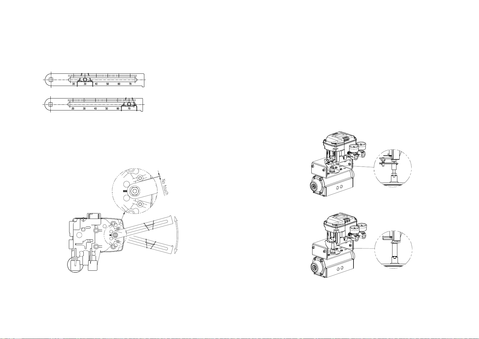
operatingconditions,butnormaldirectionisasfollowingpicture.Thatis,whenthepiping
ofactuatorandYT-2300RisdirectionA,bracketholeandindicatorattachedonthe
bottomofYT-2300Rmainshaftshouldbesamedirectionasbeinghalfcircle.
DirectionA
Attachmentdirectionofbracketandactuator
3.Setrotationpositionofactuatorstemasinitialzeropointwhichisstroke0%.Incase
ofspringreturntypesingleactuator,sincetheactuatorstemisalwaysrotatedatzero
pointwithoutsupplypressure,itiseasytocheckzeropoint.Iftheactuatorisdouble
acting,checkthatwhetheritisclockwiseorcounterclockwiseortherotationdirectionof
actuatorstemwithusingsupplypressure.
4.Setactuatorstemasinitialzeropointandinstallforkleverasthefollowingpicture.
Ensurethepositionofinitialzeropointwhenactuatorstemisclockwiseorcounter
clockwise.Installationangleofforklevershouldbeabout45degreebasedonthelinear
shaft.ButtheangleisnotrelatedtoNamurshaft.

-21-
Incaseofcounterclockwise
Incaseofclockwise
Installationpositionofforklever
5.Iftheforkleverpositionisset,lockchecknutsassembledonthebottomofforklever
withturningclockwise.Settheupperheightofforkleveras6-11mmlowerthanbracket
upperheight. Bracket6-11mm
Forklever
Actuator
Heightofbracket,forkandforklever
6.AttachYT-2300Rtothebracket.Fixtheclampingpinonthemainshaftcenterof
YT-2300Rintotheholeofforkleverandinsertconnectionbarattachedonthemain
shaftleverintoforkleverslottobelockedforkleverspring.Thisistofitthemainshaft
ofYT-2300Randthecenterofactuatorstem.Iftheyarenotfitted,productdurabilityis
gettingworseduetotoomuchforceonthemainshaftofYT-2300.
-22-
ConnectionClampingpin
shaft
Forklever
FittingthepinontheYT-2300Rmainshaftintoforkleverhole
7.FixYT-2300Rbaseandthebracketwithhexagonheadboltsandplatewasher.Itis
bettertolockthebracketandYT-2300RaftercheckingthepositionofYT-2300Rinserting
fourbolts.
AssemblystatusofYT-2300R
Pipingconnection
Note
1.Topreventmoisture,oilanddustfrombeingledintotheproduct,givecareful
considerationtothechoiceofsupplypressurecompressoranditssystem.
2.WerecommendtoattachfilterorairfilterregulatorinfrontofsupplyportofYT-2300.

-23-
Conditionsofsupplypressure
1.Dryairwhosedewpointisatleast10lowerthanthatofambienttemperature.
2.Befreefromsolidparticlesasaresultofbeingpassedthrough5orfinerfilter.㎛
3.Notcontainoilorlubricatingoil.
4.ComplywithANSI/ISA-57.31975(R1981)orISAS7.3-1975(R1981).
5.Notusedbeyontherangeof1.4-7kgf/(140-700kPA).㎠
6.Setsupplypressureofairfilterregulatoras10%higherthanoperatingpressureof
actuatorofspringrangepressure.
Conditionsofpipe
1.Removeforeignobjectsinsideofpipe.
2.Donotusesqueezedorbrokenpipe.
3.TomaintainflowrateofYT-2300,usethepipewhoseinnerdiameterismorethan
6mm(outerdiameter10mm).
4.Donotconnectthepipetoolong.Itaffectsflowrateduetothefrictioninsidethe
pipe.
Pipingconnectionwithactuator
Singleactingactuator
YT-2300seriessingleactingtypeissettouseOUT1port.Therefore,incaseofusing
singleactingtypeofspringreturnactuator,OUT1portshouldbeconnectedwithsupply
pressureportofactuator.
PipingconnectionexampleofYT-2300Lwithsingleactingactuator
-24-
PipingconnectionexampleofYT-2300Rwithsingleactingactuator
Doubleactingactuator
IncaseofYT-2300seriesdoubleactingtype,wheninputcurrentsignal,supplypressure
isoutfromOUT1port.
PipingconnectionexampleofYT-2300Lwithdoubleactingactuator
PipingconnectionexampleofYT-2300Rwithdoubleactingactuator

-25-
Powerconnection
Note
1.Beforeconnectingterminal,powermustbeshutoff.
2.Useringtypeterminalagainstoscillation,impact,etc.
3.YT-2300series(exceptPTMincludedtype)useDC4-20mAaspower.Minimum
supplycurrentis3.2mA(standardtype)and3.8mA(Harttype)andMaximumsupply
currentmustnotbeexceeded24mA.
4.IncaseofPTMtype,additionalpowershouldbesuppliedtoPTMseparately.Supply
voltageis9-27Vandmustnotbeexceeded30V.
5.Inordertoprotecttheproductthegroundterminalsshouldbegrounded.
6.Usetwistedcablewhichconductorsectionalareais1.25andissuitablefor600V㎟
asonconductortableofNECArticle310.Outerdiameterofcableshouldbe6.35-10mm.
Useshieldwireagainstelectromagneticwaveandnoise.
7.Donotinstallthecableneartheequipmentsuchashigh-capacitytransformerormotor
generatingnoise.
ThefollowingisterminalpartofYT-2300series.
TerminalplateofYT-2300
Terminalconnectionofcurrentinputsignal
1.Opencoverbyloosening4pcsofM4boltsofproductcover.
2.Loosenterminallockingboltsofterminalplatereceivingcurrentinputsignal.
-26-
Terminalconnectionofcurrentinputsignal
3.InsertacablethroughcableconnectorinYT-2300.
4.Useringtypeascableterminalinordernottocomeout.
5.Insertterminalboltsinterminalholesofcableandlockthemwith+terminaland-
terminaleachonterminalplate.Tightenterminalboltswith1.5Nm(15kfgcm)torque.
6.Besurenottochangethepolarityofterminal.
Terminalconnectionoffeedbacksignal
1.Opencoverbyloosening4pcsofM4boltsofproductcover.
2.Loosenterminallockingboltsoffeedbacksignalforpositiontransmitteronterminal
plate.
Terminalconnectionoftransmitter

-27-
3.InsertacablethroughcableconnectorinYT-2300.
4.Useringtypeascableterminalinordernottocomeout.
5.Insertterminalboltsinterminalholesofcableandlockthemwith+terminaland-
terminaleachonterminalplate.Tightenterminalboltswith1.5Nm(15kfgcm)torque.
6.Besurenottochangethepolarityofterminal.
Innerterminalconnectionforground
1.ThegroundisnecessaryforthesafetyofYT-2300seriesandsystem.
2.Thereareinsideterminalinthecenterofterminalplateandoutsideterminalbeside
outercableentry.Usinganygroundterminalisavailableandresistancemustbeless
than1000hm.
Groundterminalconnection
3.Incaseofusinginsideground,opencoverbyloosening4pcsofM4boltsofproduct
cover.
4.Inordertomaintainthegroundsafely,useringtypeasgroundcableterminalto
preventitcomingout.
A/Mswitch(Auto/Manualswitch)
ThereisA/MswitchonthebottomofYT-2300.Ifthisswitchissetasauto,supply
pressureistransmittedtoactuatorbytheoperationofYT-2300andifitissetas
manual,supplypressureofairfilterregulatoristransmittedtoactuatorregardlessof
YT-2300.
-28-
*WhenA/Mswitchissetasmanual,ensurethattoomuchpressuremustnotbe
transmittedtotheactuator.
1.Checkifthesupplypressureofairfilterregulatoristoohigh.
2.Turntheswitchclockwiseandsupplypressureofairfilterregulatoristransmittedto
actuator.
3.Ifturntheswitchcounter-clockwise,YT-2300isoperatednormally.
AutoManual
AdjustmentofA/Mswitch
Variableorifice
Theactuatorvolumeistoosmall,huntingcanbeoccurred.Inthiscase,adjustvariable
orificewithusing(-)driver,thenhuntingispreventedbyreducingflowrateofsupply
pressuretransmittingtoactuator.
Maximumopen
Minimumopen
Adjustmentofvariableorifice

-29-
AutocalibrationandBasicoperations
Warning:Sincethismakesvalveoractuatormove,beforeautocalibrationvalvemustbe
separatedfromentiresystem.
Button
YT-2300Seriesperformvariousfunctionswithusingfourbuttons.
Theshapeandpositionofbuttonsareasfollows.
<Enter>:ItisusedtogotoMainmenu,saveadjustedparametervaluesorchoosesub
menus.
<ESC>:Itisusedtoreturntopreviousmenu.
<UP>:Itisusedtomovetoanothermenuorchangeparametervalues.
<DOWN>:Itisusedtomovetoanothermenuorchangeparametervalues.
-30-
RUNMode
AfterconnectpowertoYT-2300,thefollowingisdisplayedonLCDin6seconds.
PV
Runmode ⇨ currentlydisplayedonLCD
RunonthebottomlinemeansthatYT-2300adjustvalvestrokewithreceivingoutside
signal(4-20mA)andPVmeansthenumberontheLCD.InRUNmode,valvestrokeis
changedaccordingtoinputsignal.TherearesixtypesdisplayedinRunmode.
①RunPV ValvestrokeofProcessValue(%)
②RunSV% InputsignalofSetValue(0-100%)
③RunSVmA InputsignalofSetValue(4-20mA)
④RunMV MotorcontrolledvariableofManipulate
Value(Digit)
⑤RunVel Currentvalvespeed(Digit)
⑥RunErr DifferencebetweenSVandPV(%)
Inordertochangedisplay,push<ESC>and<UP>atsametime.Wheneverpushthe
button,displayischangedinorder.Ifpush<ESC>and<DOWN>simultaneously,the
orderisoppositeandifpushonly<ESC>,displayisreturnedtoRUNmode.
Firstautocalibration
FirstautocalibrationisusuallyusedwhenYT-2300hasnotbeenset,suchasthe
occasionofinitialsettingwithvalveatvalvecompanyorreplacementwithotherproduct
inthefield.Inthiscase,entireparametersaresetbyusingAUTO2calibration.
Warning:WhenYT-2300isinstalledonthevalveinthefieldaftersetting,we
recommendtouse'AUTO1calibration'thanAUTO2calibration.Becauseoptimum
parametersaresetbyvalvecompany,itisbetterthatthoseregisteredparametersare
notchangedbyAUTO1calibration.

-31-
(1)Connectpower.Anyvaluesbetween4to20mA(DC)canbeusedforpower.After
connectingpower'READY6,5,4,3,2,1'messageisappearedinorderonLCD,which
meanspreparingtimetooperatePCBcircuitandparts.Thefollowingmessageis
displayedin6seconds.Push<ENTER>for6secondsat RUN modeand AUTOCAL
messageisappeared.
(2)Push<ENTER>andthen AUTO1 modeisstarted.
(3)Push<DOWN>and AUTO2 modeisdisplayed.
(4)Push<ENTER>at AUTO2 mode.Auto2calibrationisstartedandthenextmodes
aredisplayedinorderonLCD.Normallyittakes3-5minutesforautocalibrationin
AUTO2 modebutitcanbedifferentbyactuator'svolume.
(4)WhenAutocalibrationisdone,'COMPLETE'messageisappearedonLCD.After4
secondstheprocedureisreturnedto RUN modeandvalvestrokebycurrentinputsignal
isdisplayedaspercentage.
(5)Zero,Span,PIDparametersandRA/DAareautomaticallysetwhenAuto2calibration
iscompleted.
⇨ ⇨ ⇨
(1)Keeppushing(2)Push<ENTER>.(3)Push<DOWN>.
<ENTER>
for6seconds.
⇨ ⇨ ⇨
(4)Push<ENTER>.(5)Completed. RUNMode
Entiremodesandfunctions
Autocalibration(AUTOCAL)
ThecalibrationofYT-2300issimplyperformedbyAutocalibrationandthereare5types
ofAutocalibrationasAUTO1,AUTO2,AUTO3,BIAS,V_0.
AUTO1calibrationisusefulforusers'inthefieldandAUTO2calibrationisfor
valvecompanyorinitialparameterssettingofYT-2300.
Zero
POINT
END
POINT
KP,KI
KD BIAS V_0 RA/DA
AUTO1 ×
AUTO2
AUTO3 × ×
BIAS ××× × ×
V_0 × × × × ×
-32-
Ittakesabout2-3minutesforautocalibrationanditcanbedifferentbyactuator's
volume.AUTO1,AUTO2andAUTO3calibrationsetRA/DAautomatically.
Autocalibrationtypes
Auto1calibration(AUTO1)
AtthismodeallparametersnecessarytovalveoperationaresetexceptKP,KI,KD.Itis
usedtore-executecalibrationbyusersinthefieldafterbeingsuppliedYT-2300whose
parameterswereallsetbyvalvecompany.
(1)Push<ENTER>for6secondsat RUN modeand AUTOCAL messageisappeared.
(2)Push<ENTER>andthen AUTO1 modeisdisplayed.
(3)Push<ENTER>againat AUTO1 modeandAuto1calibrationisstarted.
(4)WhenAutocalibrationisdone,'COMPLETE'messageisappearedonLCD.After4
secondstheprocedureisreturnedto RUN modeandvalvestrokebycurrentinputsignal
isdisplayedaspercentage.
⇨ ⇨ ⇨
(1)Keeppushing(2)Push<ENTER>.(3)Push<ENTER>.
<ENTER>
for6seconds.
⇨ ⇨
(4)Completed.(5)ReturntoRUNmode
after4seconds.

-33-
Auto2calibration(AUTO2)
Allparametersnecessarytooperatevalveareset.ThiscalibrationisusedwhenYT-2300
isfirstinstalledwithvalve.Refertothechapteroffirstautocalibration.
Auto3calibration(AUTO3)
Allparametersnecessarytooperatevalvearesetexceptzeroandendpoint.This
functionisusedtore-executeautocalibrationwithoutchangingzeroandendpointafter
adjustingthemmanually.
(1)Push<DOWN>atAUTO2andAUTO3isdisplayed.
(2)Push<ENTER>andAUTO3calibrationisstarted.Thenextprocedureofthis
calibrationisassameasothercalibrations.
BIAScalibration
BIASmeansstandardvalueofmotorcontrolthatisusedinpositioner.Itisaffectedby
supplypressure,KPandothervaluesandthereforeitshouldbere-adjustedifsupply
pressureorKPischanged.Unlessthisvalueiscorrectlyset,accuracycanbeverylow.
(1)Push<DOWN>atAUTO3modeandBIASmodeisdisplayed.
(2)Push<ENTER>andBIAScalibrationisstarted.Thenextprocedureofthiscalibration
isassameasothercalibrations.
Velocitycalibration(V_0)
Thisisthefunctiontofindthestandardvaluetorecognizeaccuratevalvespeed.Unless
thisvalueiscorrectlyset,KIcontrolcanbeslowerorimpossible.Inordertocheckif
thisvalueisaccuratelyset,push<ESC>atRUNmodeandRUNVelisdisplayed.At
thistimethenumberonthebottomlineonLCDindicatesthevalueclosetozero.(After
valveisstopped)Usuallythenumberisbetween-2to2.Ifthenumberisover5,
executethisfunctionagainandresetV_0value.
(1)Push<DOWN>atBIASmodeandV_0modeisdisplayed.
(2)Push<ENTEr>andV_0calibrationisstarted.Thenextprocedureofthiscalibrationis
assameasothercalibrations.
-34-
ManualMode
Manualmodeisusedtoraiseorlowerthevalvestemmanually.Atthismodevalve
strokeisadjustedbyonlyoperatingbuttonsnotbycurrentinputsignal.Thismode
doesn'taffectcontrollingdataregisteredinYT-2300andonlymakestomovevalvestem
upanddown.
(1)Keeppushing<ENTER>atRUNmodeandAUTOCALmessageisdisplayed.
(2)Push<DOWN>andMANUALmodeisdisplayed.
(3)Push<ENTER>again.TwolinesonLCDareappeared.Theupperoneindicates
valvestrokebypercentageandtheloweroneindicatesabsolutevalueofinnerresistance
ofYT-2300.*MAmeansthatManualmodeisinoperation.
(4)Push<UP>or<DOWN>andvalvestemmovesupordown.RegardlessofRA/DA,if
push<UP>,valvestemmovesup(incaseoflinearvalve)andifpush<DOWN>,valve
stemmovesdown.Inordertomakethevalvestemmovefast,push<ENTER>with
<UP>,<DOWN>.
Buttonoperationforvalvestemmovement
(5)Push<ESC>andMANUALmodeisdisplayed.
⇨ ⇨ ⇨
(1)Push<ENTER>(2)Push<DOWN>.(3)Push<ENTER>.
for6seconds.
⇨ ⇨ ⇨
(4)Push<UP>,<DOWN>.(4)Push<ESC>.(5) MANUAL mode
Push<UP>. Valvestemisupslowly.
Push<UP>+<ENTER>atthesametime. Valvestemisupquickly.
Push<DOWN>. Valvestemisdownslowly.
Push<DOWN>+<ENTER>atthesametime. Valvestemisdownquickly.

-35-
Parametermode(PARAM)
Parametertypes
TherearefourtypesinparameterofDeadZone,KP,KI,KD.
Thesevaluesarereflectedassoonastheyarechanged,thereforetheappropriatevalues
arefoundwithcheckingvalve'smotionbyrealtime.
DeadZone(dEAdZONE)
ThisisthesectionofError%thatIcontrolisnotoperated.Iftherearehuntingor
oscillationcontinuouslyduetothefrictionbetweenstemandpacking,theyareprevented
withthisparameter.
KP
ThisisproportionconstantvalueofcorrectionthatiscorrectingbyError%.Ifthisvalue
istoobig,therecanbehuntingthoughitfindspositionbyinputsignal.Ifthevalueis
toosmall,accuracygetsworse.
KI
Thisisintegralconstantvalueaddingorsubtractingthecorrectionthatiscorrectingby
Error%onpreviouscorrectionsignal.Ifthisvalueistoobig,therecanbeoscillation.If
itistoosmall,thetimetofindtheexactpositiongetslonger.
KD
Thisisdifferentialconstantvalueaddingpreviouscorrectionsignalwithchanging
correctionsignalbyError%changerate.
AdjustmentofParameter
Deadzone(dEAdZONE)
(1)Push<ENTER>atRUNmodefor6secondsandAUTOCALmessageisappeared.
(2)Push<DOWN>twiceandPARAMmodeisdisplayed.
(3)Push<ENTER>anddEAdZONEmodeisdisplayed.
(4)Push<ENTER>againand*EAdZONEmessageisappeared.
(5)AdjsutdEAdZONEvalueby<UP>or<DOWN>.Adjustedvalueisappliedrightaway
withoutadditionaloperation,souserscaneasilycheckitsadjustmentbychangingcurrent
inputsignaltoYT-2300.Itmeansthatoptimumcontrolvalueisfoundbyadjustingvalues
duringvalveoperation.
-36-
(6)Push<ENTER>tosavethevalue.+EAdZONEmessageisonLCD.
(7)Push<ESC>threetimestoreturntoRUNmode.
⇨ ⇨ ⇨
(1)Push<ENTER>(2)Push<DOWN>twice.(3)Push<ENTER>.
for6seconds.
⇨ ⇨ ⇨ ⇨
(4)Push<ENTER>.(5)Push<ENTER>(6)Push<ESC>.
afteradjustment
by<UP>,<DOWN>.
⇨
(7)Push<ESC>twice. RUN Mode
KP
(1)-(3)AdjustmentmethodandprocedureisassameasdEAdZONE.
(4)Push<DOWN>atdEAdZONEmodeandKPmodeisdisplayed.
(5)Push<ENTER>and*KPmessageisonLCD.
(6)AdjustKPvalueswith<UP>or<DOWN>.Adjustedvalueisappliedrightaway
withoutadditionaloperation,souserscaneasilycheckitsadjustmentbychangingcurrent
inputsignaltoYT-2300.Itmeansthatoptimumcontrolvalueisfoundbyadjustingvalues
duringvalveoperation.
(7)Push<ENTER>tosavethevalue.+KPmessageisonLCD.
(8)Push<ESC>.
(9)Push<ESC>twicetoreturntoRUNmode.
⇨ ⇨ ⇨
(1)Push<ENTER>(2)Push<DOWN>twice.(3)Push<ENTER>.
for6seconds.

-37-
⇨ ⇨ ⇨ ⇨
(4)Push<DOWN>.(5)Push<ENTER>.(6)Push<ENTER>
afteradjustment
with<UP>,<DOWN>.
⇨ ⇨ ⇨
(7)Push<ESC>.(8)Push<ESC>twice. RUN Mode
KI
(1)-(3)AdjustmentmethodandprocedureisassameasdEAdZONE.
(4)Push<DOWN>twiceatdEAdZONEmode,thenKImodeisdisplayed.
(5)Push<ENTER>atKImodeand*KImessageisappearedonLCD.
(6)AdjustKIvaluewith<UP>or<DOWN>.Adjustedvalueisappliedatoncewithout
additionaloperation,souserscaneasilycheckitsadjustmentbychangingcurrentinput
signaltoYT-2300.Itmeansthatoptimumcontrolvalueisfoundbyadjustingvalues
duringvalveoperation.Push<ENTER>tosavethevalueand+KImessageisonLCD.
(7)Push<ESC>.
(8)Push<ESC>twicetoreturntoRUNmode.
⇨ ⇨ ⇨
(1)Push<ENTER>(2)Push<DOWN>twice.(3)Push<ENTER>.
for6seconds.
⇨ ⇨ ⇨ ⇨
(4)Push<DOWN>twice.(5)Push<ENTER>.(6)Push<ENTER>
afteradjustment
with<UP>,<DOWN>.
-38-
⇨ ⇨ ⇨
(7)Push<ESC>.(8)Push<ESC>twice. RUNMode
Kd
(1)-(3)AdjustmentmethodandprocedureisassameasdEAdZONE.
(4)Push<DOWN>threetimesatdEAdZONEmode,thenKdmodeisdisplayed.
(5)Push<ENTER>atKdmodeand*KdmessageisappearedonLCD.
(6)AdjustKdvaluewith<UP>or<DOWN>.Adjustedvalueisappliedatoncewithout
additionaloperation,souserscaneasilycheckitsadjustmentbychangingcurrentinput
signaltoYT-2300.Itmeansthatoptimumcontrolvalueisfoundbyadjustingvalues
duringvalveoperation.Push<ENTER>tosavethevalueand+KdmessageisonLCD.
(7)Push<ESC>.
(8)Push<ESC>twicetoreturntoRUNmode.
⇨ ⇨ ⇨
(1)Push<ENTER>(2)Push<DOWN>twice.(3)Push<ENTER>.
for6seconds.
⇨ ⇨ ⇨ ⇨
(4)Push<DOWN>(5)Push<ENTER>.(6)Push<ENTER>
threetimes.afteradjustment
with<UP>,<DOWN>.
⇨ ⇨ ⇨
(7)Push<ESC>.(8)Push<ESC>twice. RUNMode

-39-
HANDCAL
Whenautocalibrationisstarted,YT-2300setszeropointandendpointbasedonfull
stroke.
Handcalibrationtypes
PV_ZERO:Editmodetochangethezeropointofvalve.
PV_END:Editmodetochangetheendpointofvalve.
TR-ZERO:Editmodetochangethezeropointoftransmitter.
TR_END:Editmodetochangetheendpointoftransmitter.
Adjustmentofvalvezeropoint((1)~(5))andendpoint((6)~(10))
(1)Push<ENTER>atRUNmodeforsixsecondsandthenAUTOCALmodeis
displayed.Push<DOWN>threetimes,thenHANDCALmodeisdisplayed.
(2)Push<ENTER>atHANDCALmodeandPV_ZEROmodeisstarted.
(3)Push<ENTER>atPV_ZEROmodeand*PZmodeisstarted.Atthismodeitis
availabletochangevalvezeropointandvalvestemmovesautomaticallytocurrentzero
point.OnLCDvalvestrokeisdisplayedas0%.*PZmessageindicatingeditmodeof
zeropointandinnervalueshowingcurrentzeropointpositionarealsodisplayed.
(4)AdjustValvestemwithpushing<UP>,<DOWN>.Whenvalvestemisarrivedat
desirablezeropoint,saveitwith<ENTER>.+PZmessageisappearedonLCD.
(5)Push<ESC>toreturntoPV_ZEROmode.
(Push<ESC>twiceatthismodetoreturntoRUNmode.)
(6)Inordertochangevalveendpoint,push<DOWN>atPV_ZEROmodeandPV_END
modeisstarted.
(7)Push<ENTER>atPV_ENDmodeand*PEmodeisdisplayed.Atthismodeitis
availabletochangevalveendpointandvalvestemmovesautomaticallytocurrentend
point.OnLCDvalvestrokeisdisplayedas100%.*PEmessageindicatingeditmodeof
endpointandinnervalueofendpointarealsodisplayed.
(8)Adjustvalvestemwithusing<UP>or<DOWN>.Whenvalvestemisarrivedat
desirableendpoint,saveitwith<ENTER>.+PEmessageisappearedonLCD.
(9)Push<ESC>toreturntoPV_ENDmode.
(10)Push<ESC>twiceandRUNmodeisdisplayed.
(Push<DOWN>atPV_ENDmodetogotoTR_ZEROmode.)
-40-
⇨ ⇨ ⇨
(1)Push<DOWN>(2)Push<ENTER>.(3)Push<ENTER>.
threetimes.
⇨ ⇨ ⇨ ⇨
(4)Push<ENTER>(5)Push<ESC>.(6)Push<DOWN>.
afteradjustment
with<UP>,<DOWN>.
⇨ ⇨ ⇨ ⇨
(7)Push<ENTER>.(8)Push<ENTER>(9)Push<ESC>.
afteradjustment
with<UP>,<DOWN>.
⇨ ⇨
(10)Push<ESC>twice. RUN Mode
Adjustmentofzeropoint((1)~(4)),endpoint((5)~(9))oftransmitter
Ifvalvezeropointandendpointarechanged,transmitterisalsochangedautomatically.
Sousuallythere'snoneedthat
transmitterzeropointandendpoint
areadjustedbyusers,butif
transmitteroutputsignalis
unstable,transmitterzeropoint
andendpointshouldbe
adjusted.Theammetershowing
feedbacksignalisnecessaryandthe
connectionshouldbedoneasfollowingpicture.
This manual suits for next models
2
Table of contents
Other Ytc Valve Positioner manuals
Popular Valve Positioner manuals by other brands

Samson
Samson 3761 Mounting and operating instructions

CohuHD Costar
CohuHD Costar RISE 4220HD Operation manual

Baker Hughes
Baker Hughes Masoneilan SVI II AP quick start guide

KAUP
KAUP T 163SN operating manual

halstrup-walcher
halstrup-walcher PSD4 Series instruction manual

KMC Controls
KMC Controls CMC-1001 installation guide