STONEX SC200 User manual

1
SC200 User Manual
version:version 1.0
date:20140521-V1.0

2
CONTENT
part one SC200Introduction....................................................................................................................................................4
1.1 IN THE FRONT OF INSTRUMENT..........................................................................................................................5
1.2The back of the instrument ..................................................................................................................................... 6
1.3Start the receiver ................................................................................................................................................................7
part two :Webapplication .........................................................................................................................................................8
2.1 The system statue ........................................................................................................................................................ 9
2.1.1The system information............................................................................................................................... 9
2.1.2 GNSS STATUS.....................................................................................................................................................9
2.1.3 The satellite information ........................................................................................................................ 10
2.1.4 Transmit Data................................................................................................................................................ 10
2.1.5 Data Record .................................................................................................................................................... 11
2.2 Configuration............................................................................................................................................................... 13
2.2.1 Reference station......................................................................................................................................... 13
2.2.2 Network Settings.......................................................................................................................................... 14
2.2.3 Transmit dataSettings .............................................................................................................................. 17
2.2.4Record Data Settings................................................................................................................................... 17
2.2.5 Port configuration....................................................................................................................................... 18
2.2.6 Alert settings.................................................................................................................................................. 21
2.2.7 Instruments Registration........................................................................................................................ 21
2.3 Data Download ........................................................................................................................................................... 21
2.4 System Management................................................................................................................................................ 22
2.4.1 update................................................................................................................................................................ 22
2.4.2 log......................................................................................................................................................................... 23
2.4.3 security.............................................................................................................................................................. 24
2.5 help.................................................................................................................................................................................... 24

3
PART THREE:QUICK SETTING.............................................................................................................................................. 25

4
1 INTRODUCTION
STONEX®Europe completes its range of GPS/GNSS receivers introducing SC200, the new
powerful and reliable CORS (Continuosly Operating Reference Stations), designed for use as a
stand-alone reference station or as part of a GNSS infrastructure solution.
Typically used as reference stations for NTRIP servers, SC200 is the perfect equipment for
many different jobs and applications based on the management of GNSS correction data.
Designed and developed by R&D department of STONEX®Europe, the new instrument
complete the range of GNSS receivers, confirming the usual strong points of STONEX®Europe
products: performances and quality/price ratio.
SC200 integrate a 220 channels GNSS board with accurate and quick satellite fixing, it supports
a wide range of satellite signals, including GPS L2C and L5, GLONASS L1/L2 signals and
Compass constellation. In addition, the hardware is ready for Galileo (compliant to Galileo OS
SIS ICD).
The design of both SC100 and SC200 is rugged and lightweight, ensuring ease of transport in
work areas. Surveyors can operate outdoors in complete safety thanks to a strong housing
resistant to extreme weather conditions: temperatures from -30 ° to +60 ° and humidity from
0% to 100%.
The CORS stations can be set and managed by using a remote user-friendly web interface.
SC200 increases performances of the field work thanks to its many additional features:
- an internal 5000 mAh battery to work for over 16 hours without external power;
- a 4GB internal memory enabling the collection and the storage of limitless amount of data;
- Wi-Fi, 3G WCDMA modem and Bluetooth.
- raw data logging with up to 50 Hz update rate;
- 256x64 High Luminosity OLED display for easier use.
SC200 is fully compatible with most worldwide used NTRIP software and are absolutely
integrated with the desktop software NTRIP CASTER, developed and manufactured by
STONEX.
Entirely developed and realized by STONEX R&D Lab, NTRIP Caster is the brand-new software
for GNSS NTRIP network management. Its integration with SC200 makes NTRIP Caster the
essential tool for professionals’ day-to-day work. NTRIP Caster combines a fresh and easy
interface with a simple and powerful workflow for the user.

5
2 MAIN FRAME
2.1 IN THE FRONT OF INSTRUMENT
On the front panel receiver includes seven keys, four LEDs and an OLED display.
Fig. 2.1
The key function as follow:
Key/led
Function
F1
Save the current settings and back to the last menu
F2
Return to the main interface from any menu
To move the cursor up and down, to modify the parameters
To move the cursor left and right
Power key
Turn on/off the device and confirm your selection by
pressing
Bluetooth led
The led will turn into blue when the Bluetooth is linked
RTK sending led
If the RTK data is sending ,the led will be light at 1s rate.
static data led
If the static data is recording, the led will blink at 1s rate.
Power led
The led is always light as the instrument is turn on.
6
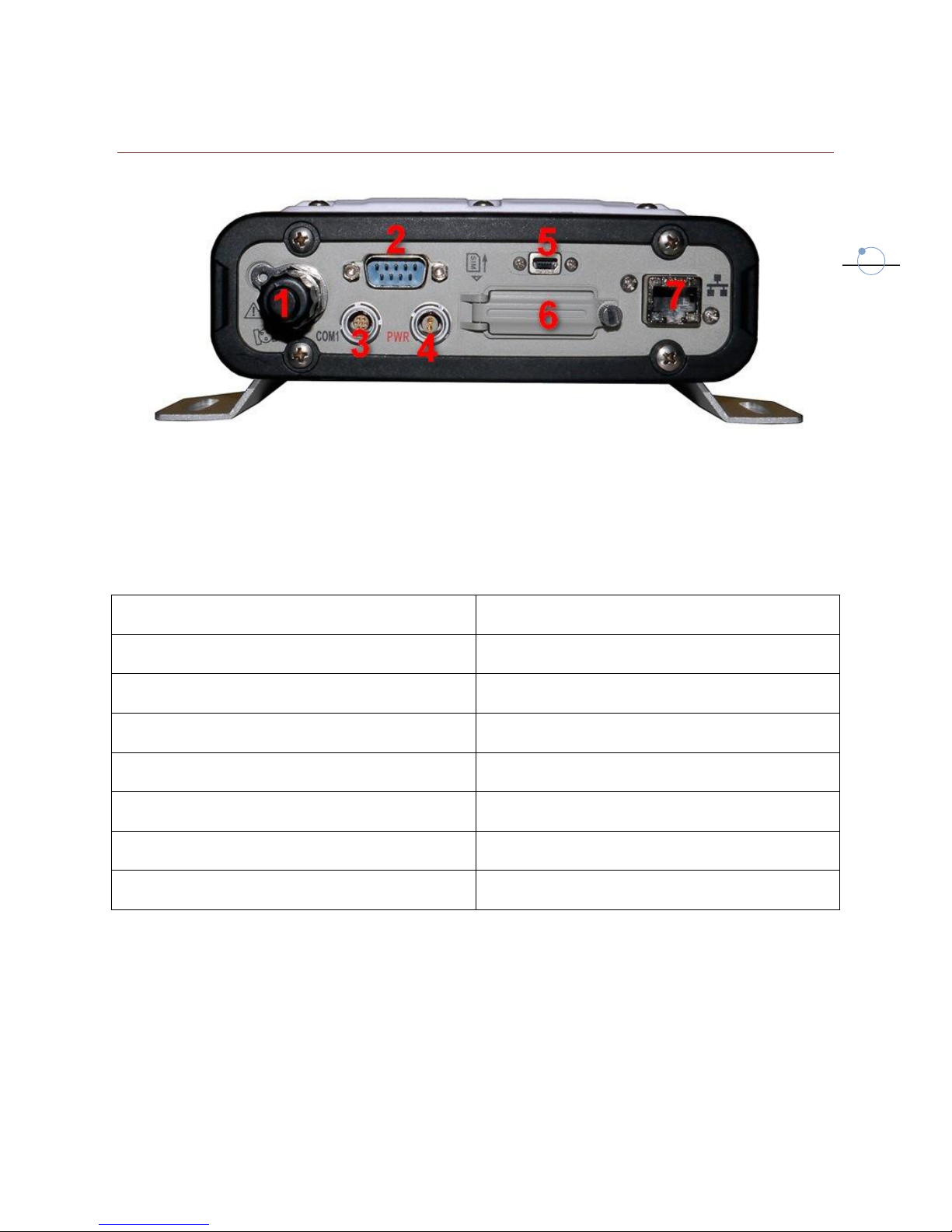
2.2 THE BACK OF THE INSTRUMENT
Fig. 2.2
SC200 included many comunication port, as described in the following Table:
Port
Function
1:TNC port/GNSS external antenna
Connect an external GNSS antenna .
2:DB9 serial port
Terminal debugging, connect external radio.
3:7pins Lemo port/COM1
COM1 data output
4:2 pins charge port
External power supply
5:Mini-USB port
Connect pc to download raw data
6:SIM card slot
Connect GPRS/CDMA
7:RJ45 Ethernet port
Connect to Internet

7
2.3 START THE RECEIVER
Long press the red power key of the receiver panel to start the SC200 receiver, after the
receiver enters initialization state. The main interface of OLED LCD screen as shown in figure
2.3.
Fig. 2.3
Press left /right key to check the current DHCP model or what is the IP address in the static
state.
Fig. 2.4
8
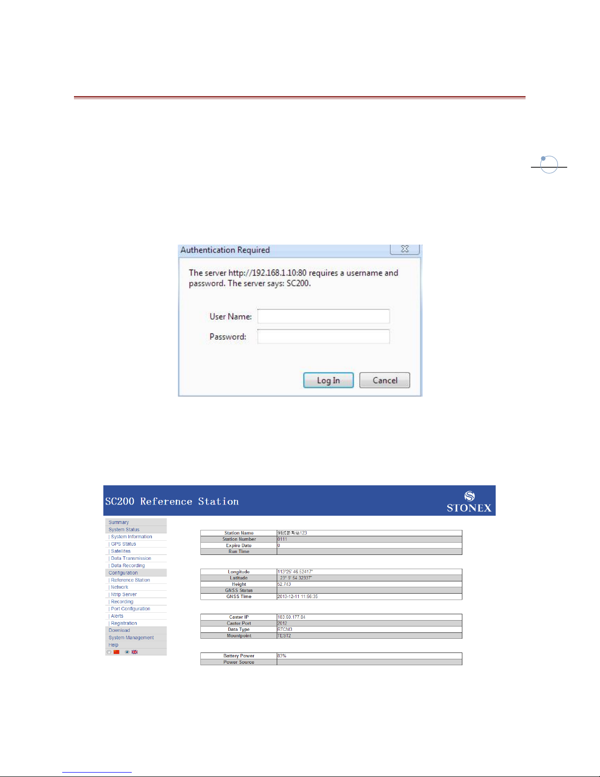
3 WEB INTERFACE
If you know which is the station IP address you can remotely connect with it. Usually both the
station and your computer are connected to a local network.
You can start an internet browser (we suggest Google Chrome or IE8) and enter the local IP
and HTTP Server Port, but if you are inside an internal network you don’t need to specify the
port. Then enter your username and password in the dialog box, the default user name and
password are: “admin” and “password”.
Fig. 3.1
After authentication, you can enter into the web interface. There is a main page called
“Summary”, where you can see a summary of information, and there are submenu where you
can change settings.
Fig. 3.2
9
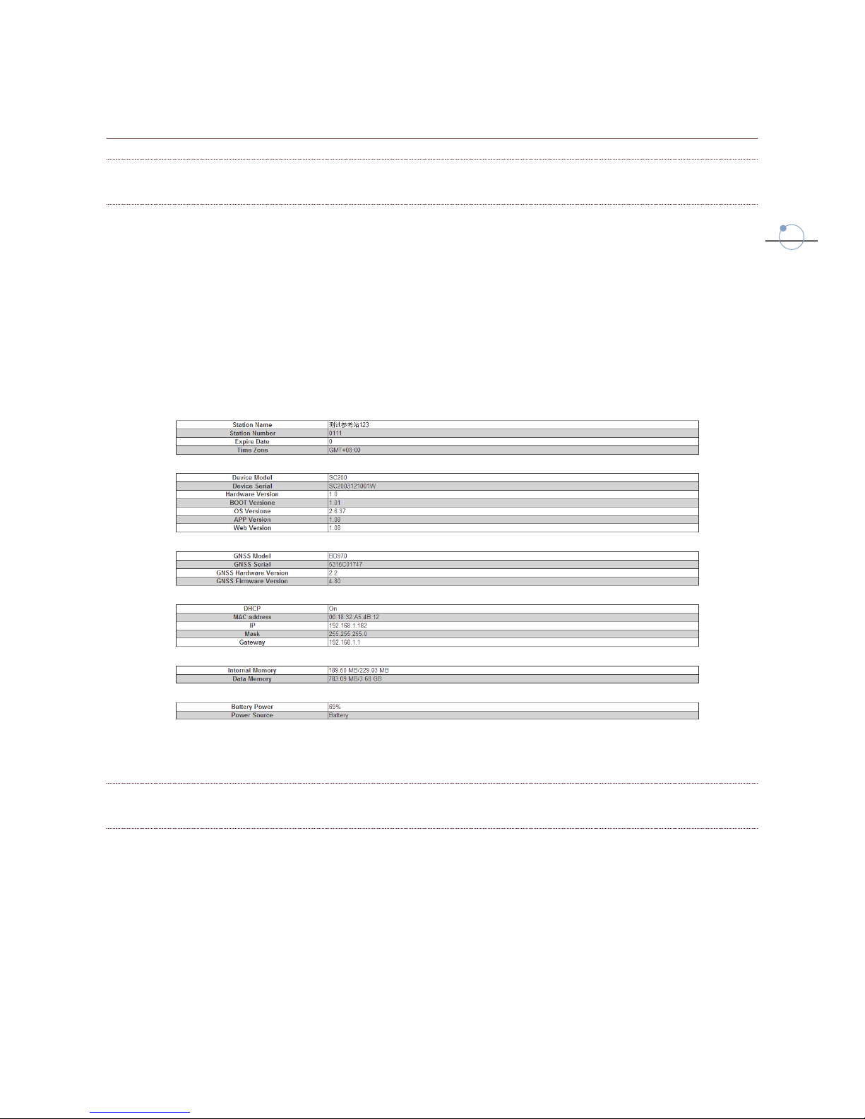
3.1 SYSTEM STATUS
3.1.1 SYSTEM INFORMATION
It displays the following information:
Station name, index, expire date and time zone.
Device model, serial number, hardware and firmware version.
GNSS internal board model, serial number, hardware and firmware version
IP address
Internal memory
Battery power level and power source.
Fig. 3.3
3.1.2 GPS STATUS
It displays the following information:
Real-time coordinate, satellite number and satellite configuration status (DOP values).
Base Station fixed coordinates.
Antenna parameters.
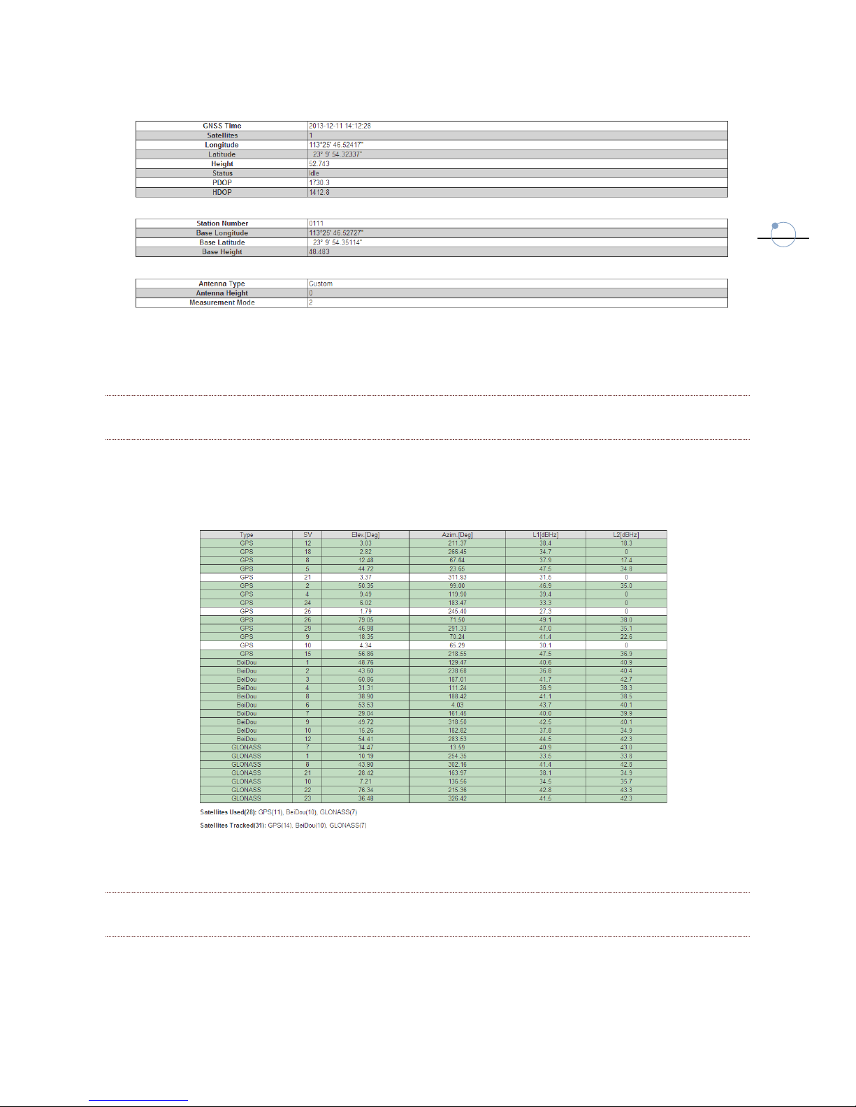
10
Fig. 3.4
3.1.3 SATELLITES
It displays the number of the used and tracked satellites, showing elevation, azimuth and
Signal-To-Noise ratio for each satellite.
Fig. 3.5
3.1.4 DATA TRANSMISSION
It displays the current settings of data transmission:
IP address and Port of Caster Server
Table of contents


