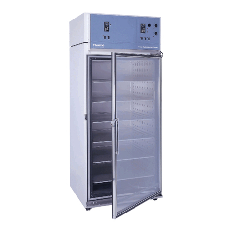
Forma Scientific 3940 Operating instructions

Forma Scientific, Inc.
Models:
3940/3949
Reach-In Incubator
Operating and Maintenance Manual
Manual No: 7003940 Rev. 0
February 1976

Models 3940 and 3949 ___________________________________________________________________________
i
Read This Instruction Manual.
Failure to read, understand and follow the instructions in
this manual may result in damage to the unit, injury to operat-
ing personnel, and poor equipment performance.
CAUTION! All internal adjustments and maintenance must
be performed by qualified service personnel.
Refer to the serial tag on the back of this manual.
The material in this manual is for information purposes
only. The contents and the product it describes are subject to
change without notice. Forma Scientific, Inc. makes no repre-
sentations or warranties with respect to this manual. In no event
shall Forma Scientific, Inc. be held liable for any damages, direct
or incidental, arising out of or related to the use of this manual.
MANUAL NUMBER 7003940
0 -- 2/76 Original manual
REV ECN DATE DESCRIPTION By

Models 3940 and 3949 ______________________________________________________________________________Safety
ii
Important operating and/or maintenance instructions. Read the accompanying text carefully.
Ce symbole attire l'attention de l'utilisateur sur des instructions importantes de fonctionnement et/ou d'entretien. Il
peut être utilisé seul ou avec d'autres symboles de sécurité. Lire attentivement le texte d'accompagnement.
Wichtige Betriebs- und/oder Wartungshinweise. Lesen Sie den nachfolgenden Text sorgfältig.
Importante instruccions de operacion y/o mantenimiento. Lea el texto acompanante cuidadosamente.
Potential electrical hazards. Only qualified persons should perform procedures associated with this symbol.
Ce symbole attire l'attention de l'utilisateur sur des risques électriques potentiels. Seules des personnes qualifiées
doivent appliquer les instructions et les procédures associées à ce symbole.
Gefahr von Stromschlägen. Nur qualifizierte Personen sollten die Tätigkeiten ausführen, die mit diesem Symbol beze-
ichnet sind.
Potencial de riesgos electricos. Solo personas das capacitadadas deben ejecutar los procedimientos asociadas con este
simbulo.
Equipment being maintained or serviced must be turned off and locked off to prevent possible injury.
Risques potentiels liés à l'énergie. L'équipement en entretien ou en maintenance doit être éteint et mis sous clé pour
éviter des blessures possibles.
Geräte, an denen Wartungs- oder Servicearbeiten durchgeführt werden, müssen abgeschaltet und abgeschlossen wer-
den, um Verletzungen zu vermeiden.
El equipo recibiendo servicio o mantenimiento debe ser apagado y segurado para prevenir danos.
Hot surface(s) present which may cause burns to unprotected skin, or to materials which may be damaged by elevated
temperatures.
Présence de surface(s) chaude(s) pouvant causer des brûlures sur la peau non protégée, ou sur des matières pouvant
être endommagées par des températures élevées.
Heiße Oberfläche(n) können ungeschützter Haut Verbrennungen zufügen oder Schäden an Materialien verursachen,
die nicht hitzebeständig sind.
Superficias calientes que pueden causar quemaduras a piel sin proteccion o a materiales que pueden estar danados
por elevadas temperaturas.
√ Always use the proper protective equipment (clothing, gloves, goggles, etc.)
√ Always dissipate extreme cold or heat and wear protective clothing.
√ Always follow good hygiene practices.
√ Each individual is responsible for his or her own safety.

Models 3940 and 3949 _________________________________________________________________________Service
iii
Do You Need Information or Assistance on Forma Scientific
Products?
do, please contact us 8:00 a.m. to 7:00 p.m. (Eastern Time) at:
1-740-373-4763 Direct
1-888-213-1790 Toll Free, U.S. and Canada
1-740-373-4189 FAX
http://www.forma.com Internet Worldwide Web Home Page
fservice@forma.com Service E-Mail Address
If you
Our staff can provide information on pricing and give you quotations. We
can take your order and provide delivery information on major equipment items or make
arrangements to have your local sales representative contact you. Our products are listed on the
Internet and we can be contacted through our Internet home page.
Our staff can supply technical information about proper setup,
operation or troubleshooting of your equipment. We can fill your needs for spare or replacement
parts or provide you with on-site service. We can also provide you with a quotation on our
Extended Warranty for your Forma products.
Whatever Forma products you need or use, we will be happy to discuss your
applications. If you are experiencing technical problems, working together, we will help you
locate the problem and, chances are, correct it yourself...over the telephone without a service
call.
When more extensive service is necessary, we will assist you with direct factory trained
technicians or a qualified service organization for on-the-spot repair. If your service need is
covered by the warranty, we will arrange for the unit to be repaired at our expense and to your
satisfaction.
Regardless of your needs, our professional telephone technicians are available to assist
you Monday through Friday from 8:00 a.m. to 7:00 p.m. Eastern Time. Please contact us by
telephone or fax. If you wish to write, our mailing address is:
Forma Scientific, Inc.
Millcreek Road, PO Box 649
Marietta, OH 45750
International customers please contact your local Forma Scientific distributor.
Sales Support
Service Support

Models 3940 and 3949 ___________________________________________________________________Table of Contents
Table of Contents
Section 1 - Introduction . . . . . . . . . . . . . . . . . . . . . . . . . .2 - 1
1.1 Standard Features . . . . . . . . . . . . . . . . . . . . . . . . . . . .2 - 1
1.2 Auxiliary Equipment . . . . . . . . . . . . . . . . . . . . . . . . . .2 - 1
Section 2 - Specifications . . . . . . . . . . . . . . . . . . . . . . . . .2 - 1
Section 3 - Control Panel Operation . . . . . . . . . . . . . . .3 - 1
3.1 Main Power Switch & Indicator Light . . . . . . . . . . . .3 - 1
3.2 Refrigeration Switch & Indicator Light . . . . . . . . . . . .3 - 1
3.3 Defrost Switch & Indicator Light . . . . . . . . . . . . . . . .3 - 1
3.4 Digital Temperature Controller . . . . . . . . . . . . . . . . . .3 - 1
3.5 Overtemp Safety Control, Indicator Light, and . . . . . . . .
Audible Alarm . . . . . . . . . . . . . . . . . . . . . . . . . . . . . . .3 - 1
3.6 Humidity Controller . . . . . . . . . . . . . . . . . . . . . . . . . . .3 - 1
3.7 Humidity Range Selector Switch . . . . . . . . . . . . . . . .3 - 1
3.8 Humidify Switch and Indicator . . . . . . . . . . . . . . . . . .3 - 1
3.9 Relative Humidity Indicator . . . . . . . . . . . . . . . . . . . .3 - 1
3.10 Dehumidify Switch and Indicator Light . . . . . . . . . .4 - 1
Section 4 - Installation and Set-Up . . . . . . . . . . . . . . . . .4 - 1
4.1 Location . . . . . . . . . . . . . . . . . . . . . . . . . . . . . . . . . . .4 - 1
4.2 Water and Drain Connections . . . . . . . . . . . . . . . . . . .4 - 1
4.3 Power Connection . . . . . . . . . . . . . . . . . . . . . . . . . . . .4 - 2
4.4 Preparing the Humidification System . . . . . . . . . . . . .4 - 2
4.5 Initial Settings - Start-Up Procedure . . . . . . . . . . . . .4 - 2
4.6 Humidity System Operation . . . . . . . . . . . . . . . . . . . .4 - 2
4.7 Setting the Overtemp Safety Thermostat . . . . . . . . . .4 - 2
Section 5 - Routine Maintenance . . . . . . . . . . . . . . . . . .6 - 1
5.1 Cleaning the Incubator . . . . . . . . . . . . . . . . . . . . . . . .6 - 1
5.2 Cleaning Stainless Steel . . . . . . . . . . . . . . . . . . . . . . .6 - 1
5.3 Cleaning the Humidity Boiler / Immersion Heaters . .6 - 1
Section 6 - Service . . . . . . . . . . . . . . . . . . . . . . . . . . . . . .6 - 1
6.1 Accessing the Electrical Components . . . . . . . . . . . . .6 - 1
6.2 Checking and Recalibrating the Digital Temperature
Controller . . . . . . . . . . . . . . . . . . . . . . . . . . . . . . . . . .6 - 1
6.3 Recalibrating the Dial Thermometer . . . . . . . . . . . . .6 - 2
6.4 Replacing the Overtemp Probe and Thermostat . . . . .6 - 2
6.5 Replacing the Humidity Sensor . . . . . . . . . . . . . . . . .6 - 2
6.6 Replacing the Relative Humidity Indicator . . . . . . . .6 - 2
Replacing the Recorder and Probe(s) . . . . . . . . . . . .6 - 3
6.5 Removing the Top Section . . . . . . . . . . . . . . . . . . . . .6 - 3
Section 7 - Spare Parts . . . . . . . . . . . . . . . . . . . . . . . . . . .7 - 1
Section 8 - Electrical Schematics . . . . . . . . . . . . . . . . . .8 - 1
Warranty Information
iv

Models 3940 and 3949 __________________________________________________________Introduction / Specifications
2 - 1
Section 1 - Introduction
1.1 Standard Features
~ Positive horizontal airflow to ensure stable temperature
uniformity throughout the chamber to within ±0.25°C.
~ Adjustable intake and exhaust vents regulate fresh air
exchange without disturbing close temperature control.
~ Solid state temperature control adjusts setpoint in 0.1°C.
~ An overtemperature safety thermostat protects cultures
from overtemperature deviations by activating an audible
and visual alarm, then interrupting power to the chamber
heaters when temperature rises to a predetermined
overtemp safety limit.
~ A direct dial humidity controller permits establishing
chamber relative humidity in a range from above ambient
to 96%.
~ A swing-out control panel provides access to control com-
ponents should servicing become necessary.
1.2 Auxiliary Equipment
Extra Shelves: Additional stainless steel, non-perforated
shelves are available. The shelves slide easily into shelf
channels and can be removed for cleaning.
Catalog #505071
CH/P Portamatic CO2Control System: Model 3057
portable digital automatic system for Reach-In Incubators.
Catalog #3057
Solid-faced Door: Polished stainless steel door for light-
tight applications.
Catalog #921055
Digital Thermometer: Panel-mounted thermometer pro-
vides direct digital temperature display in 0.1°C incre-
ments.
Catalog #260154
Duplex Outlet: Weather-proof, mounted inside the incuba-
tor chamber.
Catalog (115V) #505099, (230V) #505094
Thru-wall Access Port: 1-3/4” diameter port with plug,
centered on the right side of the chamber interior.
Catalog #505101
Tissue Culture Shelves: The 11” x 16” stainless steel
shelves for culture dishes are designed for stacking to
increase incubator storage space. Minimum order is six
shelves.
Catalog #500171
Section 2 - Specifications
Construction
Interior Polished stainless steel, 2B finish
Exterior Reinforced steel
Shelves Non-perforated stainless steel
Finish Polyurethane enamel
Capacity and Weight
Net 850 lbs. (385 kg) nominal
Volume 29 cu. ft. (823 liters)
Shelf Capacity 19 shelves w/ 103.3 sq. ft. space
Heating and Refrigeration
Heater (2) Wirewound
Refrigeration 1/4 HP, air-cooled condensing unit
R-12 refrigerant
Defrost Hot gas
Humidity
Control ±5% RH
Range Above ambient to 96%
Utility Connections
Drain Connection 3/8” NPT (drain trap is required)
Water Connection 1/8” NPT
Water Consumption Initial filling - approx. 3 gallons
Consumption Rate Maximum - 1 gallon per hour
Electrical
3940 208-220V, 1 PH, 60Hz, 3W,
17.0 FLA
3949 220-240V, 1 PH, 50/60Hz, 2W,
16-23 FLA
Dimensions
Exterior 38”W x 88.5”H x 32”F-B
(96.5 cm x 225 cm x 79 cm)
Interior 31”W x 60”H x 27”F-B
(78.7 cm x 152.4 cm x 68.6 cm)
Continuing research and improvements may result in speci-
fication changes at any time. Performance plus or minus
the least significant digit unless otherwise specified.

Models 3940 and 3949_________________________________________________________________Control Panel Operation
3 - 1
3.5 Overtemp Safety Control, Indicator Light, and
Audible Alarm
The overtemp safety thermostat should be set slightly
above the operating temperature of the incubator. In the event
of an overtemp condition, the overtemp safety thermostat will:
• Activate the audible alarm and the overtemp indicator
light.
• Interrupt power to the heaters and maintain the incubator’s
cabinet temperature at the overtemp safety control point.
Note: The overtemp control is not directly calibrated. The
numbers (0 to 10) on the dial are for reference only and do not
correspond to any specific temperature.
If an overtemp condition occurs, the alarm can only be
silenced by raising the overtemp safety thermostat setting.
However, the cause of the problem must be determined and cor-
rected before normal operation under the main temperature con-
troller is resumed.
3.6 Humidity Controller
The humidity controller knob is used to set the level of
humidity desired in the chamber.
3.7 Humidity Range Selector Switch
The humidity range selector switch is used to select the
proper humidity range for the desired level of humidity in the
chamber.
~Low Range: 10% to 50% rH (Lower Scale)
~High Range: 40% to 96% rH (Upper Scale)
The range selector switch must be set before the desired
percent of humidity is established on the humidity controller.
3.8 Humidify Switch and Indicator
The humidify switch controls the power to the humidity
boiler circuit. The boiler heaters will operate only if there is suf-
ficient water in the boiler. The humidity indicator light is acti-
vated when the humidity switch is in the On position.
3.9 Relative Humidity Indicator
The relative humidity indicator provides a direct readout of
chamber humidity in both ranges.
Section 3 - Control Panel Operation
3.1 Main Power Switch & Indicator Light
The main power switch controls power to the incubator.
The main power indicator lights when the power switch is on
and the unit is receiving power.
3.2 Refrigeration Switch & Indicator Light
This switch controls power to the refrigeration system. The
refrigeration switch should be in the On position when the incu-
bator setpoint temperature is 4°C above ambient or below. The
refrigeration indicator lights when the refrigeration switch is On
and the compressor is receiving power.
3.3 Defrost Switch & Indicator Light
The defrost switch controls power to the defrost system.
The defrost timer is factory set to provide two 15-minute
defrost cycles during a twenty-four hour period. The defrost
switch should be in the On position when the temperature set-
point is 10°C or below.
CAUTION! Failure to turn the defrost switch On when
required will cause icing of the refrigeration coil, which in
turn will impair performance.
The defrost timer is energized by the main power switch,
but timed defrosting can occur only when the defrost timer is in
the On position.
The defrost indicator lights when the defrost switch is On
and the incubator is in a defrost cycle. The indicator light will
go out when the defrost cycle is completed.
3.4 Digital Temperature Controller
The solid state digital thumbwheel switch controls power
to the incubator heater circuit. On a demand for heat, the tem-
perature controller energizes the heaters to bring the tempera-
ture up to setpoint.
On the controller face are three manually adjustable rotary
discs, for direct dialing of the chamber setpoint temperature.
Temperature settings are made by gently rotaing the indiviual
discs until the digits corresponding to the desired setpoint tem-
perature show in the controller windows. The disc on the
extreme right is used for setting temperature in 0.1°C. Settings
0 to 0.9°C can be selected using this disc. The two discs to the
left are adjustable from 0 to 60°C.
The indicator light, adjacent to the temperature controller,
cycles with the chamber heaters to indicate when there is a
demand for heat to meet setpoint requirements.

Section 4 - Installation and Set-Up
4.1 Location
Locate the unit on a firm, level surface in an area of mini-
mum ambient temperature fluctuation. A minimum of twelve
(12) inches of clearance is required at the top of the incubator
and a minimum of three (3) inches of clearance is required at
the rear of the incubator. This space is necessary to allow ade-
quate air flow around the refrigeration system.
4.2 Water and Drain Connections
To ensure continuous satisfactory operation of the incuba-
tor, it is recommended tha only distilled water be used in the
reservoir. In localities where the water has a high mineral con-
tent, the use of distilled water is especially important.
IMPORTANT: Purity of the distilled water used in the incuba-
tor humidifier reservoir must be within the 50K Ohm/cm to 1M
Ohm/cm range to protect and prolong the life of the stainless
steel unit. Use of tap water, or distilled water outside the speci-
fied range will decrease the operating life of the unit and will
void the warranty.
The water inlet is the 1/8” NPT connection located at the
top left side of the back of the incubator. Water inlet pressure at
the unit should be from 15 to 40 PSI. To facilitate service, it is
recommended that a manually operated shut-off valve be
installed between the main power supply and the incubator. A
3/8” NPT drain connection is required.
Note: A drain trap is necessary on the drain line in order to
maintain correct air flow within the chamber.
The humidity reservoir will require approximately three
gallons of water on the initial filling. The maximum water con-
sumption rate therafter will be approximately one gallon per
hour.
CAUTION! To prevent mineral buildup on heater coils and
boiler walls, it may be necessary to clean the boiler and
immersion heaters with a non-metallic abrasive pad and flush
thoroughly every two to three months.
Models 3940 and 3949_________________________________________________________________Installation and Set-Up
3.10 Dehumidify Switch and Indicator Light
When the dehumidify switch is in the On position, power
to the boiler heaters are interrupted and the refrigeration system
is energized to provide control for drying. The dehumidify light
comes on when the dehumidify switch is in the On position.
If the dehumidity switch is On when a defrost cycle occurs,
the dehumidify light may cycle on and off to reflect the action
of the humidity controller.
Note: The dehumidify switch should be on only when the incu-
bator is being operated without refrigeration and a lower level
of rH (above ambient) is desired.
Humidity is removed from the cabinet is processed through
the evaporator in the refrigeration system.
4 - 1

Models 3940 and 3949 ________________________________________________________________Installation and Start-Up
4.6 Humidity System Operation
CAUTION! Do not attempt to operate the humidity system
without water in the boiler. To do so will cause the boiler
heater to overheat, and the system will be shut down by the
thermostat.
Following stabilization of the chamber temperature:
1. Set the humidity range selector switch to the proper
range for the percent humidity desired.
2. Set the humidity controller to the desired percent humid-
ity.
3. Set the humidity switch to the On position.
4.7 Setting the Overtemp Safety Thermostat
Allow the chamber temperature and humidity to stabilize,
then set the overtemp safety thermostat as follows:
1. Turn the overtemp control knob slowly counterclock-
wise until the audible alarm sounds and the overtemp
indicator lights.
2. Turn the overtemp control knob clockwise approximate-
ly two units on the scale. The alarm should be silenced
and the overtemp indicator light should go out.
The overtemp safety thermostat is now set a few degrees
above the control temperature setpoint. When the chamber tem-
perature rises to the overtemp control point, the alarm system
will activate, power to the heaters will shut off, and the cham-
ber temperature will be maintained at the overtemp control
point.
When an overtemp condition occurs, the cause must be
determined and corrected before normal operation under the
main temperature controller can be resumed.
Note: When the chamber temperature control setpoint is
changed, the overtemp safety thermostat must be reset to
accommodate the change.
4.3 Power Connection
With all the control switches Off, connect the incubator to
an adequate power source. See the electrical data plate mounted
on the unit for exact electrical specifications.
4.4 Preparing the Humidification System
CAUTION! The humidity boiler is dry at initial start-up.
Boiler must be filled before turning the heat switch On.
Before operating the incubator, follow the steps outlined
below:
1. Turn the overtemp safety thermostat fully clockwise.
2. Set the humidity range switch to Low.
3. Turn the humidity control knob to the lowest possible
setting.
4. Turn the main power switch On.
5. Turn the humidity switch On.
6. Open the control panel. Water should be flowing to the
water level tank mounted on the side of the humidifica-
tion boiler. When a constant trickle of water begins to
flow through the clear plastic tubing, the humidier boiler
is operational.
4.5 Initial Settings - Start-Up Procedure
When the humidification system is operational, the incuba-
tor may be placed into operation. Preset the controls as follows:
Main Power Switch . . . . . . . . . . . . . . . . . . . . . . . . . . . . . .OFF
Temperature Controller . . . . . . . . . . . . . . . . . .Desired Setpoint
Overtemp Safety Thermostat . . . . . . . . . Fully Clockwise (10)
Refrigeration Switch . . . . . . . . . . . . . . . . . . . . . . . . . . . . . OFF
Defrost Switch . . . . . . . . . . . . . . . . . . . . . . . . . . . . . . . . . .OFF
Humidity Switch . . . . . . . . . . . . . . . . . . . . . . . . . . . . . . . .OFF
Humidity Range Selector Switch . . . . . . . . . . . . . . . . . . . .Low
Humidity Controller . . . . . . . . . . . . . . . . . . . .Fully Clockwise
Dehumidity Switch . . . . . . . . . . . . . . . . . . . . . . . . . . . . . . .OFF
Turn the main power switch On. The main power indicator
light should be activated.
If the temperature control setpoint is 4°C above ambient or
below, the refrigeration switch should be turned On. The refrig-
eration indicator light will be activated.
4 - 2

Section 6 - Service
CAUTION! Servicing must be performed by qualified service
personnel only!
WARNING!
High voltage is present behind the control panel. Power must
be disconnected before the control panel is opened.
6.1 Accessing the Electrical Components
To gain access to the electrical components, open the front
of the control panel. Grasp the left side of the control panel
housing and pull gently but firmly, down and out.
6.2 Checking and Recalibrating the Digital tempera-
ture Controller
A periodic check of temperature calibration is recommend-
ed to ensure the accuracy of the controller.
To check the accuracy of the digital temperature controller,
place a calibrating thermometer of known quality and accuracy
inside the incubator chamber. Allow time for the temperature
reading on the thermometer to stabilize. If the temperature indi-
cated by the calibrating thermometer and the digital controller
differ, recalibration is necessary.
To recalibrate the controller:
1. Adjust set point to 0°C and allow temperature to stabi-
lize.
2. Open control panel and locate temperature control cir-
cuit board mounted directly behind thumbwheel switch.
3. Locate the adjustment screw marked ZERO.
4. To raise chamber temperature, turn zero adjustment
screw counterclockwise in small increments. To lower
temperature, turn the zero adjustment screw clockwise.
Allow temperature to stabilize between adjustments.
Example: If the chamber temperature is measured at 1°C by a
high qualifty thermometer or indicating pyrometer, and the
thumbwheel switch reads 0°C, turn the calibration screw clock-
wise. This will lower the chamber temperature and will, with
further adjustments, bring the temperature into alignment with
the thumbwheel switch.
Turning the screw counterclockwise will raise the chamber tem-
perature.
5. Adjust set point to 36°C and allow temperature to stabi-
lize.
Models 3940 and 3949___________________________________________________________Routine Maintenance / Service
6 - 1
Section 5 - Routine Maintenance
5.1 Cleaning the Incubator
The chamber interior should be cleaned with alcohol and/or
soap and water. The interior panels should be sterilized with a
general-use laboratory disinfectant.
The cabinet exterior may be cleaned with soap and water
or with any non-abrasive commercial commercial spray cleaner.
The Thermopane glass door may be cleaned with commer-
cial glass cleaner or with a solution of ammonia and water.
5.2 Cleaning Stainless Steel
The continued cleanliness of the stainless steel utilized in
Forma products has a direct effect on the appearance and opera-
tion of the unit. The following pages are intended as a guide for
specific cleaning problems.
CAUTION! Do not use chlorinated solvents on stainless steel
as they can cause rusting and pitting.
Note: Do not use volatile or aromatic solvents for cleaning
inside the cabinet as their residue can contaminate the cabinet
environment.
The Thermopane glass door may be cleaned with commer-
cial glass cleaner or with a solution of ammonia and water.
General instructions: Use the mildest cleaning procedure
that will do the job effectively. To ensure maximum effective-
ness, always rub in the direction of the finish polish lines. Be
sure to rinse the surface thoroughly after every cleaning opera-
tion. To avoid water marks, wipe the surfaces dry.
5.3 Cleaning the Humidity Boiler / Immersion Heaters
Depending upon the quality of water used in the humidifi-
cation system, it may be necessary to clean the boiler and
immersion heaters with a nonmetallic abrasive scrubber and
flush every 2 to 3 months.

7. Pull the overtemp probe up through the access hole and
into the control panel.
8. Follow the wires from the probe to the thermostat
mounted on the control panel. Clip the plastic ties hold-
ing the overtemp cable to the existing wiring.
9. Pull the overtemp knob on the control panel off.
10. Remove the two screws that hold the overtemp assembly
to the control panel.
11. Disconnect the two wires from the back of the thermo-
stat assembly.
12. Pull the entire assembly out of the panel, and remove the
unit.
13. Replace the thermostat and probe with Forma part
#270010 by reversing the above procedure.
Note: Reseal the probe access hole with Permagum and retie
the overtemp cable to the existing wires after replacing the
probe.
6.5 Replacing the Humidity Sensor
1. Disconnect the incubator from the power source.
1. Locate the probe mounting plate in the center of the
right side of the incubator interior.
2. Open the mounting plate by removing the screws that
hold it in place.
3. Locate the humidity sensor mounted on the inside of the
panel in a black housing. Note the angle of the probe.
4. Grasp and unplug the probe from the probe cable.
5. Replace the probe with Forma part #245055 by revers-
ing the above procedure. Be sure to mount the probe at
the same angle as it was originally mounted.
6.6 Replacing the Relative Humidity Indicator
1. Disconnect the unit from the power source.
2. Open the control panel access door.
3. Remove the two wires from the hack of the indicator.
The red wire is connected to the (+) terminal, and the
black wire is connected to the (-) terminal.
4. Remove the four bolts holding the unit in place.
5. Pull the indicator out of the control panel.
6. Place the humidity indicator with Forma part #260083
by reversing the above procedure.
6. Locate the adjustment screw marked “SET POT SPAN”.
7. To raise chamber temperature, turn set pot span screw
clockwise in small increments. To lower temperature,
turn the set pot span screw counterclockwise. Allow
temperature to stabilize between adjustments.
Example: If the chamber temperature is measured at +37.8°C
by a high quality thermometer or indicating pyrometer, and the
thumbwheel switch reads 36°C, turn the calibration screw coun-
terclockwise. This will lower the chamber temperature and will,
with further adjustment, bring the temperature into alignment
with the thumbwheel switch. Turning the screw clockwise will
raise the chamber temperature.
8. Allow chamber temperature to stabilize, then recheck.
Repeat calibration procedure as necessary.
6.3 Recalibrating the Dial Thermometer
Note: Recalibration is necessary only if the thermometer is not
reading accurately.
1. Place a thermometer of known accuracy in the center of
the incubator chamber, and allow sufficient time for sta-
bilization.
2. Being careful not to scratch the surface, remove the
plastic ring from the dial thermometer by snapping it off
the dial with a thin blade knife.
3. Determine the margin of error between the test instru-
ment and the dial indicator.
4. Hold the dial steady, and use a small screwdriver to turn
the center calibration screw. Turn it clockwise if the dial
is to be moved to the left and counterclockwise if the
dial is to be moved to the right.
5. When the thermometer is recalibrated, replace the plastic
ring and cover.
6.4 Replacing the Overtemp Probe and Thermostat
1. Disconnect the unit from the power source.
2. Remove the incubator ceiling by remove the screws
holding it in place.
3. Remove the top three screws from the top of the right
duct cover.
4. Lean the duct sheet out, and remove the Permagum seal
from around the probe access hole.
5. Remove the 15” copper capillary overtemp probe by
extracting the two plastic clips that hold the probe in
place.
6. Open the control panel.
Models 3940 and 3949 _____________________________________________________________________________Service
6 - 2

Replacing the Recorder and Probe(s)
1. Disconnect the unit from the power source.
2. Open the incubator door, and locate the probe mounting
plate attached to the center of the right interior wall.
Remove the mounting plate.
2. Single pen recorders have only one long stainless steel
probe, attached to the lower end of the mounting plate.
Remove the probe by carefully sliding it out of the hous-
ing.
Dual pen recorders have the long stainless steel probe
plus a wet bulb probe attached to the back of the mount-
ing plate. Remove the screws securing the mounting
plate and slide the wet bulb probe out of its housing.
3. Remove the screws securing the ceiling of the incubator
and remove the ceiling.
4. Remove the top three screws on both edges of the right
duct sheet.
5. Lean the duct sheet out in order to remove the
Permagum seal from around the probe access hole.
6. Remove the two screws located on the left side of the
control panel and open the control panel door. Remove
any Permagum from around the access hole.
7. Pull the probe(s) carefully up through the hole.
8. Follow the probe cable(s) to the back of the recorder,
and carefully clip any plastic ties holding the cable(s) to
other wiring.
9. Remove the three screws securing the recorder and pull
it carefully out from the front of the control panel.
10. Replace the recorder with the correct Forma part.
Note: When replacing the recorder and probe(s), retie the probe
cable(s) to the existing wires.
IMPORTANT: Be extremely careful when installing the new
recorder to avoid kinking or bending the probe capillary tubes.
6.5 Removing the Top Section
The following instructions are intended to provide a
sequential plan for removing the top assembly from the 3900
Series Reach-In incubator. It is sometimes necessary to remove
the top when moving the incubator through low doorways.
The work area should be well-lighted and provide adequate
space.
If the top is to be removed from the incubator, disconnect
the incubator from the power source before proceeding.
Disconnect the inlet water supply and the drain.
In order to remove the top assembly, the ten 5/16” x 4” hex
bolts that secure the assembly to the main part of the cabinet
will need to be removed. In addition, probes serving the various
controls and/or instruments will need to be disconnected from
the probe mounting bracket.
Models 3940 and 3949 _____________________________________________________________________________Service
Prior to lifting the top section from the incubator, a suitable
support arrangement for the top should be provided.
Carpenter’s horses or other means should be provided so that
the underside of the top (and capillaries) are suspended to pre-
vent damage.
Procedure:
1. Remove all test material from the incubator chamber.
2. All temperature and/or humidity sensing probes are
mounted on a probe mounting bracket on the right side
of the incubator chamber. Remove the nuts securing the
bracket and then remove the probes from the bracket.
Note the location and configuration of the probes.
3. The sensing bulb capillaries are routed behind the duct
sheet up to the access port at the top of the unit behind
the control panel.
Note: Route all the probes between the duct sheet and the out-
side wall of the chamber so that when the top is raised, all
probes will move freely up and out. Do not kink or bend the
capillaries.
4. The humidifier boiler drain line (3/8” clear tygon) is
routed down through the access port and is secured to
the condensate drain tube on the center left side of the
incubator (as viewed from the rear). Free the drain line,
by pulling it away from the float tank (behind the con-
trol panel) and routing it down through the access port.
5. Open the control panel (up to 90°) by grasping the left
side and pulling outward until the catch releases.
6. Loosen the top gasket around each of the air exhaust
vents by turning the screw.
7. Remove the eight screws from the top cover of the incu-
bator.
8. Remove the four screws from each of the vent caps on
the top cover of the incubator. The top cover can now be
removed.
9. Remove the nine 5/16” x 4” hex head bolts, lockwash-
ers, and two flatwashers which secure the top assembly
to the cabinet. Note the washer arrangement on the
bolts.
10. Remove the black trim gasket located at the junction of
the top assembly and the main incubator section. The
ends of the gasket have been joined together at the rear
of the incubator.
Note: When raising the top section, notice the gasket seal at the
top opening of the incubator chamber. The gasket must be cor-
rectly positioned when reinstalling the top on the chamber.
11. Slowly lift the entire top assembly up and off the lower
chamber section while carefully guiding the capillaries
and sensing bulbs out of the chamber area. The top
assembly and bottom chamber section separate where
the black gasket was located. Place the top assembly
onto carpenter’s horses or other support arrangement.
6 - 3

Section 7 - Spare Parts
Qty Stock # Description
1 245055 Sensor Assembly, rH
1 245215 Temperature Probe/Digital Control
2 250012 Relay DPDT 10A, 120V
1 250079 Relay, Delay, 3-300 Sec., 220 V
1 250190 Contactor, 2 Pole, 25A 1
1 255068 Switch, Toggle, SPSDT
2 260039 Switch, Toggle, DPST
1 260081 Indicator Module, RH
1 260082 Controller, RH Relay
1 260083 Indicator, Dir Read
1 310028 Set Pot, 5K, 1W, RH
1 260116 Temp Control Triac/Digital
1 260002 Knob, 2-1/4”, Black w/Skirt
1 400073 Thermostat B-10, Snap, P.D.
1 285020 Sonalert, 110VAC, 2.9 KHz
2 285379 Triac, 15A, 400 PIV
1 285476 Switch, Dgtl Thumbwheel, 0-69.9°C
2 285606 Switch, Toggle, SPST
1 285607 Switch, Toggle, 3 PDT
1 260004 Knob, Black, 2-1/4”, w/Clear Skirt
7 290113 Light, Ind, Neon, Red, 5/16, 115V
1 851301 Temp Insert
1 851702 Humidity Insert
1 940235 Thermometer, 2” Dial
1 1211101 Resistor, Carbon, l00K, 0.5W, 10%
2 1211104 Resistor, Carbon, l00K, 0.5W, 10%
1 1212104 Resistor, Fixed, 10K, .5W
12 190012 Channel, Shelf
6 505071 Shelf, 30.625x25.812
1 505087 Boiler
1 420400 Gasket, Door, 36 x 65, Magnetic
1 475510 Door, 36 x 65
1 54011 Gasket, Vent Cap, l.4 x 1.75
1 54021 Gasket, Boiler, 1/4 x 2 x 2, Silicon
Models 3940 and 3949 _______________________________________________________________________Spare Parts
7 - 1
12. Reinstall the top assembly by reversing the above proce-
dure. Exercise care particularly when:
• Placing and aligning the sealer gasket on the 1/2”
flange on top of the chamber when lowering the top
into place.
• Routing the temperature and/or humidity sensors and
capillaries to prevent kinking or bending them.
• Mounting the temperature and/or humidity sensor
bulbs on the mounting brackets.
• Tightening the top mounting bolts alternately to ensure
balanced pressure on the sealer gasket.

Models 3940 and 3949 ______________________________________________________________Rear View Dimensions
8 - 1

Models 3940 and 3949 ________________________________________________________________Humidity Evaluation
8 - 2

Models 3940 and 3949 ______________________________________________________________Refrigeration Schematic

Models 3940 and 3949 __________________________________________________________________Electrical Schematics
9 - 1

Models 3940 and 3949 __________________________________________________________________Electrical Schematics
Other manuals for 3940
2
This manual suits for next models
1
Table of contents
Other Forma Scientific Accessories manuals

Forma Scientific
Forma Scientific 3980 User manual
Forma Scientific
Forma Scientific 3250 User manual
Forma Scientific
Forma Scientific 3950 User manual

Forma Scientific
Forma Scientific 310 Series Operating instructions
Forma Scientific
Forma Scientific 3920 Operating instructions

Forma Scientific
Forma Scientific 3158 User manual

Forma Scientific
Forma Scientific 3920 Operating instructions

Forma Scientific
Forma Scientific 3980 User manual

Forma Scientific
Forma Scientific 3158 User manual

Forma Scientific
Forma Scientific 3911 Operating instructions


