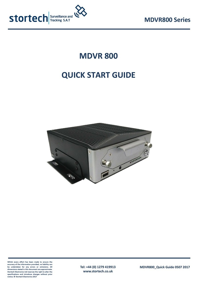
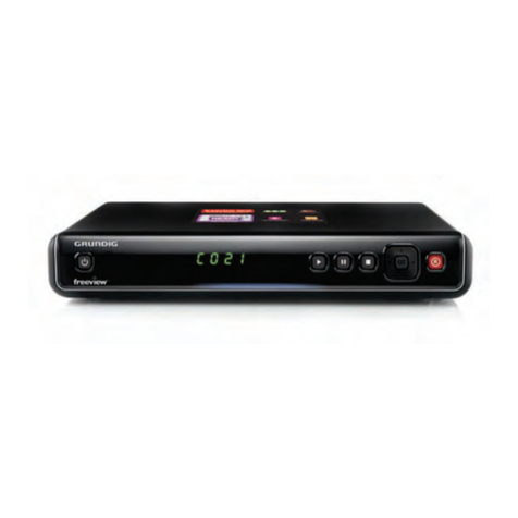
Stortech MDVR402 User manual

Tel: +44 (0) 1279 419913
www.stortech.co.uk
Whilst every effort has een made to ensure the
accuracy of the information provided, no lia ility can
e undertaken for any errors or omissions. All
dimensions stated in this document are approximate.
Stortech Electronics Ltd reserves the right to alter the
specifications and introduce changes without prior
notice. © Stortech Electronics 2017
MDVR402_
Quick Guide
0507
2017
MDVR402 Series
MDVR 402
QUICK START GUIDE

Tel: +44 (0) 1279 419913
www.stortech.co.uk
Whilst every effort has een made to ensure the
accuracy of the information provided, no lia ility can
e undertaken for any errors or omissions. All
dimensions stated in this document are approximate.
Stortech Electronics Ltd reserves the right to alter the
specifications and introduce changes without prior
notice. © Stortech Electronics 2017
MDVR402_
Quick Guide
0507
2017
MDVR402 Series
Introduction & Warnings
Before installing please read the following warnings carefully. Stortech CCTV
strongly recommends that all connections and installations are carried out by
qualified personnel.
PLEASE READ THIS BEFORE ATTEMPTING INSTALLATION AND USE
The recorder uses a DC power supply; input DC range is 8V 36V. Please pay
attention to VDD and GND when connecting the power. DO NOT make the DVR
short circuit.
• Initial power must be over 30W (Specific power consumption will vary
depending on the external equipment).
• Power supply must be over 60W.
• From the vehicle supply to the DVR all power cables must be able to
withstand 5 Amps or more.
• Install the equipment in the dry and avoid damp, drip, water spray etc.
• To extend the life of the equipment, please install the low vibration part of
the vehicle; we recommend a horizontal installation position.
• The equipment must be installed in the vehicle interior with adequate
ventilation. Do not install in a closet type environment.
• Ensure that equipment is away from any heat source in the vehicle, is not
covered and is located as far as possible from an electromagnetic
environment, which may cause strong interference.
• Ensure that passengers and drivers cannot interfere or damage any
components of the equipment.
• The installation and all materials must bear the correct fuse rating.
• It is recommended that the power cords are kept away from heat any source
and are sealed to prevent water and oil ingress that may result in short
circuit.
• In the absence of professional guidance, please do not open or attempt to
install the equipment.
Attention: The device will automatically format the hard disk/SD card to pre allocate
the storage space before starting to record video.

Tel: +44 (0) 1279 419913
www.stortech.co.uk
Whilst every effort has een made to ensure the
accuracy of the information provided, no lia ility can
e undertaken for any errors or omissions. All
dimensions stated in this document are approximate.
Stortech Electronics Ltd reserves the right to alter the
specifications and introduce changes without prior
notice. © Stortech Electronics 2017
MDVR402_
Quick Guide
0507
2017
MDVR402 Series
1. Remote Controller
Tips:
In the video preview interface, you can undertake the following actions:
• Press F2 to enter Quick Setting, you can change the device number, server IP and
port information.
• Press LOGIN to enter the menu, direct input password:
Administrator: 666666, User: 000000.
• Press INFO to display the signal strength, dial up connection status, hardware
and software versions, storage capacity, etc.
• Press 1 8 to enlarge the corresponding channel video, press ESC to return to
four preview videos.
• Press the playback key directly, start the video playback.
Device number and Phone number in the MDVR must be the same they are
used as the CMS device ID numbers.

Tel: +44 (0) 1279 419913
www.stortech.co.uk
Whilst every effort has een made to ensure the
accuracy of the information provided, no lia ility can
e undertaken for any errors or omissions. All
dimensions stated in this document are approximate.
Stortech Electronics Ltd reserves the right to alter the
specifications and introduce changes without prior
notice. © Stortech Electronics 2017
MDVR402_
Quick Guide
0507
2017
MDVR402 Series
2. Device Front and Rear Panel
LED Indicators
• [PWR] Power LED
• LED light means the system has powered on
• [VLOS] Video Indicator
• LED On – Video loss; LED Off – Video normal
• [SD1] SD indicator
• LED Off – Card does not exit; LED On Card recording; LED Flash slow – card exists but not
recording
• [SD2] SD Indicator
• The same as with SD1 indicator
• [IR] Infrared remote control receiving interface
****Status LED Flashing in circulation means the device is booting up****
Back Panel
• [DC IN] Power port
• Red cable connect power positive, black cable connect power negative, yellow line ACC
signal cable
• [AV1 AV4] 1 4 CH Video and Audio input interface include DC 12V output
• [AVOUT] Video and Audio output interface, include DC 12V output
• [GPS] Built in GPS module antenna interface
• [3G] Built in wireless communication module antenna interface
• [SENSOR] Extension Function interface
• [VGA] Video output interface
If you need timed or ignition recording, please connect the ACC cable to the vehicle ACC supply

Tel: +44 (0) 1279 419913
www.stortech.co.uk
Whilst every effort has een made to ensure the
accuracy of the information provided, no lia ility can
e undertaken for any errors or omissions. All
dimensions stated in this document are approximate.
Stortech Electronics Ltd reserves the right to alter the
specifications and introduce changes without prior
notice. © Stortech Electronics 2017
MDVR402_
Quick Guide
0507
2017
MDVR402 Series
3. DVR Wiring Installation Introduction
Before use, please make sure you have read this fully efore installing and first
use.
Device Power Connection:
Only connect the DVR to the vehicle power supply. The power for cameras and
monitors are all supplied by MDVR via aviation connectors and its built in DC 12V
output.
Use the ignition switch to control the video recorder delay timer operation.
Red cable must connect to the positive of the vehicle storage battery. Black
cable connects to the negative. Yellow cable must connect to an independent
ignition switch (ACC).
Switch Connection (Indoor test usually use this way)
Red cable and yellow cable together connect power positive of the car storage
battery, whilst black cable connect negative.
Camera connects via AV IN. Monitor connects via BNC connector of AV out of
PANEL. If it is not a standard aviation connector, please use the aviation
conversion line mentioned in the addenda. Black side is DC 12V output. White
side is Audio output. Yellow side is Video output.
★
★★
★ Use the ignition switch or (ACC) to control the MDVR record delay time operation.

Tel: +44 (0) 1279 419913
www.stortech.co.uk
Whilst every effort has een made to ensure the
accuracy of the information provided, no lia ility can
e undertaken for any errors or omissions. All
dimensions stated in this document are approximate.
Stortech Electronics Ltd reserves the right to alter the
specifications and introduce changes without prior
notice. © Stortech Electronics 2017
MDVR402_
Quick Guide
0507
2017
MDVR402 Series
4. Main Configuration Instructions
SIM card dial up parameters should be set in 3/4G Setup, customers can consult
APN and other related parameters from their SIM card operators.
If you need to change the server, press F2 to enter quick settings page, device
number and mobile phone number must be the same to set as the device ID, the
monitoring centre is the IP address of the server.
After mounting SD card, SIM card and antenna, press “info” button to check the
signal strength, dial up state and the server connection state.
The next page shows the
disk and RS232 status;

Tel: +44 (0) 1279 419913
www.stortech.co.uk
Whilst every effort has een made to ensure the
accuracy of the information provided, no lia ility can
e undertaken for any errors or omissions. All
dimensions stated in this document are approximate.
Stortech Electronics Ltd reserves the right to alter the
specifications and introduce changes without prior
notice. © Stortech Electronics 2017
MDVR402_
Quick Guide
0507
2017
MDVR402 Series
The following shows positioning, and the server connection is successful.
The 4CH MDVR can switch camera input types and quality. In Video Recording
Set—Basic Record Reset, choose AHD or Normal camera, after saving the MDVR will
reboot automatically;
In Mixture mode, 1,2CHANNEL is AHD high definition input, 3,4CHANNEL are only
analogue standard definition input.

Tel: +44 (0) 1279 419913
www.stortech.co.uk
Whilst every effort has een made to ensure the
accuracy of the information provided, no lia ility can
e undertaken for any errors or omissions. All
dimensions stated in this document are approximate.
Stortech Electronics Ltd reserves the right to alter the
specifications and introduce changes without prior
notice. © Stortech Electronics 2017
MDVR402_
Quick Guide
0507
2017
MDVR402 Series
Video Recording Quality Setting Main Code Steam.
Video QUAL mode, 0 is the highest quality and this is for the Video recording going
on to HDD
In System setting Power on/off, it can be changed to delay shutdown time, and the
default layout for full screen (PTZ) 5CH screen (IPC), 9CH (8CH DVR).

Tel: +44 (0) 1279 419913
www.stortech.co.uk
Whilst every effort has een made to ensure the
accuracy of the information provided, no lia ility can
e undertaken for any errors or omissions. All
dimensions stated in this document are approximate.
Stortech Electronics Ltd reserves the right to alter the
specifications and introduce changes without prior
notice. © Stortech Electronics 2017
MDVR402_
Quick Guide
0507
2017
MDVR402 Series
When Double SD cards or HDD+ SD card is recording, if needed the second card or
HDD can be changed to support different record modes and priority levels such as
Loop video recording without overwriting.
In video preview interface, directly press , can make video search replay.
5. Audio/Video Interface Definition
The device supports 4 camera channels AV1 AV4. The aviation joint provides a
secure connection for vehicle environments
.

Tel: +44 (0) 1279 419913
www.stortech.co.uk
Whilst every effort has een made to ensure the
accuracy of the information provided, no lia ility can
e undertaken for any errors or omissions. All
dimensions stated in this document are approximate.
Stortech Electronics Ltd reserves the right to alter the
specifications and introduce changes without prior
notice. © Stortech Electronics 2017
MDVR402_
Quick Guide
0507
2017
MDVR402 Series
Other Interface Connection Details
The DVR Power Interface
Sensor Interface ports as follows:
Among them,
SENSOR IN* is an
Alarm Input port;
SENSOR_OUT is
an Output Control port.
Alarm in / Output Connection Mode
Alarm inputs usually use a High Level (12V) input to trigger. They can be used to
connect a SOS button and driving status connections such as: braking, turning, door
open etc.
The following is the brake light (STOP) detection diagram. When braking the device
can detect the high level or the low level change of state.

Tel: +44 (0) 1279 419913
www.stortech.co.uk
Whilst every effort has een made to ensure the
accuracy of the information provided, no lia ility can
e undertaken for any errors or omissions. All
dimensions stated in this document are approximate.
Stortech Electronics Ltd reserves the right to alter the
specifications and introduce changes without prior
notice. © Stortech Electronics 2017
MDVR402_
Quick Guide
0507
2017
MDVR402 Series
The Alarm Output is a Relay Switched Output. It can connect to an Acoustic Optic
alarm. Remote Oil/Power cut off etc. If you are switching high power then we
strongly recommend you connect an external relay.
The alarm output diagram as below:
Alarm Out
Hard Disk pre allocated technology means that multiple channel videos will only
write in a single video file. Features: 1. This avoids corrupted files being created by
repeatedly read and wipe file fragmentation; 2 .Avoid long distance repeatedly
reading and writing to the hard disk magnetic read; 3. Protect FAT table and
catalogue area, reduce the disk failure. Through the technology a ove we can
ensure the relia ility and sta ility of the disk, prolong the life of the SD card / hard
disk, video data security;
The hard disk drive will automatically create two partitions, respectively, used to
store system logs and video files.
After a new hard disk is inserted into the DVR and when it starts for the first time,
the DVR will automatically format the storage device to pre allocate the storage
space. In the first instance, the loading time of storage device takes 2 3 minutes, to
create the single volume and start recording. Subsequent vehicle start ups will
record much faster.

Tel: +44 (0) 1279 419913
www.stortech.co.uk
Whilst every effort has een made to ensure the
accuracy of the information provided, no lia ility can
e undertaken for any errors or omissions. All
dimensions stated in this document are approximate.
Stortech Electronics Ltd reserves the right to alter the
specifications and introduce changes without prior
notice. © Stortech Electronics 2017
MDVR402_
Quick Guide
0507
2017
MDVR402 Series
FAQ (Trou leshooting)
Q: When a device issue appears please help us by providing as much information as
possible.
Check Device Item No and Firmware Version and contact us with a full detailed
description of the issue.
Q: Video Output Lost
Check the DVR: Device Input Power, Power Cable Connections, GND fuse, and
Connect Red and Yellow cables of power together to see if it is an ACC fault.
Check the Screen Power or check to see if the screen has changed to a different AV
channel. Check the connection of Video Output and Screen Cable.
Q: Device keeps rebooting.
Check working power, if there is low power the device will keep rebooting.
HDD/SD Card error; remove storage device and turn on device to check.
Q: Device on with HDD but not recording.
Check SD/HDD if formatted. If not, enter Main GUI System Set Format, format
HDD/SD card.
If not recording check Timed Recording mode, if this is set to yes it will not record all
of the time. Also check HDD light is on.
GPS related FAQ
Q: I have GPS but GPS coordinate information is not displayed.
Check if GPS module exists
Check GPS Antenna connection; suggest it is installed on the outside of the vehicle
3G/4G Wireless Module related FAQ
Q: If using 3G/4G what should we check?
Choose Settings wireless module WCDMA, EVDO, TD SCDMA module settings should
not be the same as the SIM card and network provider settings.
Check the Server IP and Port are set correct. If 3G/4G signal is strong for transmission
of 3G/4G video. Check 3G/4G Antenna connection and position to make sure 3G/4G
signal is optimised.
Q: When device is offline or no video, what should be done first?
Press INFO key to enter the system info page. Check if SIM card exists, 3G/4G signal
and dialing status, Antenna connection, check SIM card 3G/4G flow, and change to a
new SIM card check again. 3G/4G signal strong but dialing fail, check if center IP &
Ports are set correct. Check if Device ID is already occupied
Q: WIFI Signal 60/100 connect failure.
General condition, connection is not a problem when the signal intensity is up to
60/100 if the WIFI setup is correct. If the device cannot be found in the LAN, you
should check setting SSID and password, IP Address, Encryption Type and
Authentication Mode.
This manual suits for next models
2
Table of contents
Other Stortech DVR manuals
