Nadatel SDVR-4300 User manual

USER GUIDE
4 Channel MPEG-4 Triplex
Digital Video Recorder
(Ver. 1.1)
About this user guide
Before installing and using this unit, please read this user guide carefully.
The specifications and information are subject to change without notice for quality improvement.

Safety Precautions
Explanation of Graphical Symbols
This symbol indicates the presence of important operating and
maintenance (servicing) instruction in the literature accompanying the
product.
This symbol indicates the presence of unprotected ”dangerous voltage”
within the product’s enclosure that may be of sufficient magnitude to
constitute a risk of electric shock to persons.
Cautions
This product has multiple-rated voltages (110v and 220v).
See installation instructions before connecting to the power supply.
This product uses a Lithium battery.
To avoid of risk of explosion, do not replace the battery on the main board by anything other
than a Lithium battery. Dispose of used batteries according to the manufacturer’s instructions.
This equipment and all communication wirings are intended for indoor use only.
To reduce the risk of fire or electric shock, do not expose the unit to rain or moisture.
2

Warnings
Installation and servicing should be performed only by qualified and experienced personnel.
Power off the DVR when connecting cameras, audio or sensor cables.
The manufacturer is not responsible for any damage caused by improper use of the product or
failure to follow instructions for the product.
The manufacturer is not responsible for any problems caused by or resulting from the user
physically opening the DVR for examination or attempting to fix the unit. The manufacturer may not
be held liable for any issues with the unit if the warranty seal is removed.
3

Contents of DVR package
The package contains the main unit and its components as specified below. When you purchase
the unit, please check to ensure the components specified below are included.
DVR Set
Client Software CD
(Including Manual)
Remote Controller
Battery1.5V (AAA x 2EA)
Adaptor and Power cable
IDE HDD Cable
HDD Screws and Rubber rings
4

Compatible HDD Models
COMPANY MODEL SIZE RPM BUFFER INTERFACE
HDS728080PLAT20 80 GB 7200 RPM 2 M E-IDE
HDS721680PLAT80 82 GB 7200 RPM 8 M E-IDE
HDT722516DLAT80 160 GB 7200 RPM 8 M E-IDE
HDT722516DLAT80 164 GB 7200 RPM 8 M E-IDE
HDS722525VLAT80 250 GB 7200 RPM 8 M E-IDE
HDT722525DLAT80 250 GB 7200 RPM 8 M E-IDE
HDT725025VLAT80 250 GB 7200 RPM 8 M E-IDE
HDT725032VLAT80 320 GB 7200 RPM 8 M E-IDE
HITACHI
HDS725050KLAT80 500 GB 7200 RPM 8 M E-IDE
MAXTOR 6L300R0 300 GB 7200 RPM 16 M E-IDE
SP0822N 80 GB 7200 RPM 2 M E-IDE
SAMSUNG SP1604N 160 GB 7200 RPM 2 M E-IDE
WD1600BB-22GUA0 160 GB 7200 RPM 2 M E-IDE
WD2000BB-00GUA0 200 GB 7200 RPM 8 M E-IDE
WD2500BB-00KEA0 250 GB 7200 RPM 8 M E-IDE
Western Digital
WD5000AAKB 500 GB 7200 RPM 16 M E-IDE
ST3400-15ACE 40 GB 7200 RPM 2 M E-IDE
ST3800-12ACE 80 GB 7200 RPM 2 M E-IDE
ST31200-25ACE 120 GB 7200 RPM 2 M E-IDE
ST31600-22ACE 160 GB 7200 RPM 2 M E-IDE
ST3300820ACE 300 GB 7200 RPM 8 M E-IDE
ST3300831ACE 300 GB 7200 RPM 8 M E-IDE
ST3400832ACE 400 GB 7200 RPM 8 M E-IDE
ST3400820ACE 400 GB 7200 RPM 8 M E-IDE
ST3500641A 500 GB 7200 RPM 16 M E-IDE
ST3750840ACE 750 GB 7200 RPM 8 M E-IDE
Seagate
ST3750640A 750 GB 7200 RPM 16 M E-IDE
5

Specifications
INPUT 4 composite BNC (NTSC/PAL) – 1.0Vp-p
1 composite BNC (NTSC/PAL) – 1.0Vp-p
VIDEO
OUTPUT (Selectable)
1 VGA
ALARM INPUT & OUTPUT 4 & 1
OS RTOS
COMPRESSION MPEG-4
VIDEO FORMAT NTSC PAL
RESOLUTION 352x240, 704x480 352x288, 704x576
RECORDING SPEED MAX. 120fps/4CH(352x240/CH)
MAX. 30fps/4CH(704X480/CH)
MAX. 100fps/4CH(352x288/CH)
MAX. 25fps/4CH(704X576/CH)
MODE Manual, Motion, Sensor, and Schedule
RECORD
METHOD By Resolution, fps & Quality
MULTI TASK TRIPLEX Record, playback and transfer
CONTROL UNIT IR Type Remote Control and Front keys
SERIAL PORT CONSOLE 1 RS-232C
DYNAMIC IP Supported by DDNS
LAN PORT 1 10/100-base T Ethernet
NETWORK
FUNCTIONS Live, Search, P/T/Z/F
HDD CAPACITY 1EA Max. 750GB
NETWORK Still Image & Video dataBACKUP
USB STICK Still Image & Video data
ADAPTOR Input: AC100-240V, 50/60Hz, 3AELECTRONICAL
SPECIFICATION CONSUMPTION About 25W
TEMPERATURE 5°C ~ 40°C
HUMIDITY 30% ~ 90%
ENVIRONMENTAL
SPECIFICATION
SIZE
DIMENSION 340(W) X 250(D) X 60(H)mm
6

INDEX
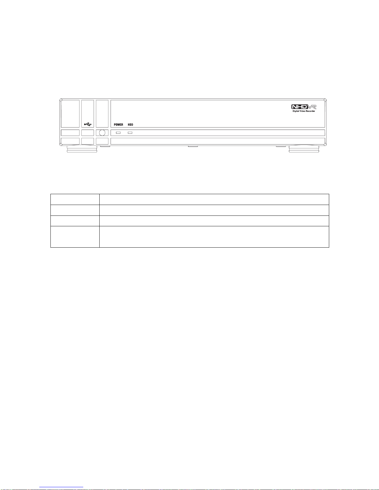
1. FRONT PANEL AND REMOTE CONTROLLER...........................................................10
2. REAR PANEL AND CONNECTIONS............................................................................12
3. SETTING UP THE DVR.................................................................................................13
3-1. Setup - Main Screen................................................................................................................................13
3-2. Setup – Live Mode...................................................................................................................................15
3-3. Setup – Recording Mode........................................................................................................................16
3-3-1. Motion Zones......................................................................................................................................17
3-3-2. Recording Schedules .........................................................................................................................18
3-4. System......................................................................................................................................................19
3-5. Network ....................................................................................................................................................22
3-5-1. Ports ...................................................................................................................................................23
3-5-2. Network types.....................................................................................................................................24
3-5-2-1. LAN..................................................................................................................................................24
3-5-2-2. DHCP ..............................................................................................................................................24
3-5-2-3. ADSL (PPPOE)................................................................................................................................25
3-6. Storage .....................................................................................................................................................26
4. LIVE & SEARCH...........................................................................................................28
4-1. Live Window.............................................................................................................................................28
4-2. SEARCH window.....................................................................................................................................30
4-2-1. EVENT Search ...................................................................................................................................30
4-2-2. TIME LINE Search..............................................................................................................................31
4-2-3. GO TO ................................................................................................................................................32
4-2-4. GO FIRST...........................................................................................................................................32
4-2-5. GO LAST............................................................................................................................................32
4-2-6. LOG List..............................................................................................................................................32
7

4-2-7. ARCHIVE Search ...............................................................................................................................33
4-3. Playback mode ........................................................................................................................................34
5. ARCHIVING AND BACKUP..........................................................................................35
5-1. Archiving Still images or Video..............................................................................................................35
5-2. Backup still images or videos on USB memory stick .........................................................................36
5-3. Playing backup file..................................................................................................................................36
6. NETWORK – BY AN EXCLUSIVE VIEWER.................................................................37
6-1. Overview...................................................................................................................................................37
6-2. Minimum PC requirements.....................................................................................................................38
6-3. Installing the program.............................................................................................................................38
6-4. Live viewer...............................................................................................................................................39
6-5. Search and Playback Viewer..................................................................................................................41
6-5-1. Backup................................................................................................................................................42
6-6. PC System configuration........................................................................................................................42
6-6-1. General...............................................................................................................................................42
9-6-2. Site......................................................................................................................................................43
9-6-3. Event...................................................................................................................................................43
9-6-4. Record................................................................................................................................................44
9-6-5. Disk.....................................................................................................................................................44
7. NETWORK – BY AN WEB-BROWSER VIEWER.........................................................45
7-1. Download Web Brower Viewer and Connection ..................................................................................45
7-2. Main Features ..........................................................................................................................................46
7-2-1. Live.....................................................................................................................................................46
7-2-2. Search and Playback..........................................................................................................................47
8

APPENDIX ........................................................................................................................48
1. How to register DDNS (Dynamic Domain Name Server) ........................................................................48
1-1. Setting of NETWORK Setup menu.........................................................................................................48
1-2. Checking Mac address on the rear panel of DVR and Registration No.............................................48
1-3. Registration at DDNS..............................................................................................................................49
2. Network access using Domain name .......................................................................................................51
9

1. Front Panel and Remote controller
The following information will help you operate the front panel controls.
Figure 1.1 Front panel
Table 1.1. Front LED and Port
Name Description
POWER LED light is on when power is applied to the system.
HDD LED light is on when the system is recording video data.
USB port There is a USB port located on the left side of the front panel. This USB port is used to
archive footage into a USB storage device. (USB 2.0 connector)
10

F/REW Jump 60 seconds backward
PLAY/PAUSE Play/Pause
F/ADV Jump 60 seconds forward
FF Fast Forward
SETUP Setup menu screen
SEQ Sequence of Full or Quad view
RECORD Manual recording
SEARCH Search menu screen
DIRECTION
SELECT
Direction or number 1 to 4
Enter
ID DVR ID
(ID Button + DVR ID number)
ESC Esc
NUMBER Channel 0 to 9
Figure 1.2 Remote controller Table 1.2. Description of remote controller
11

2. Rear Panel and Connections
Figure 2.1. Rear Panel
Table 2.1. Rear panel connections
Connection Purpose
VIDEO IN Four connectors for video input. Connect camera output to Video-in (NTSC/PAL)
VIDEO OUT Composite video output in NTSC or PAL format
VGA Connector for VGA monitor
RS-232 For engineering use only
SENSOR IN
Connector for sensor device connection. 4 sensors can be connected to the
equipment sensor 1, 2, 3, 4 are dedicated to Video channel 1, 2, 3, 4, respectively.
Either normal open (NO) or normal close (NC) sensor can be selected for each
sensor. Simple On/Off switching.
Connect two signal lines of sensor (infrared rays sensor, heat perception sensor,
magnetic sensor) to the desired sensor number. (You can set the type-NC or NO- of
sensor at “Setup” mode).
NOTICE
SENSOR inputs need dried contact only. Do not input any electric signal.
Connector for alarm device connection.
ALARM OUT Provides simple On/Off switching using relay. 0.5A/125V, 1A/30V
RJ45 connector for LAN connection
LAN
Apply 12V DC using the DC adaptor supplied with the equipment.
DC 12V
Select VGA monitor or CVBS (Composite Video Blanking Sync) monitor.
Do not change the setting when the power is on.
SWITCHES When the position of the switch is changed, the DVR should be
rebooted to apply the new setting.
12

3. Setting up the DVR
The following sections detail the initial setup of the DVR
3-1. Setup - Main Screen
When you press the SETUP button, the DVR will ask for a password. The default password is 1111, which
can be entered by pressing the up button ( ) 4 times and then pressing the SEL button. We
recommend you protect the system by assigning a new password immediately.
Figure 3.1.1. Setup menu screen
13

SETUP LIVE OSD
SEQUENCE
SEQ-DWEL TIME
EVENT BEEP
OSD CONTRAST
CHANNEL DISPLAY, SEQ LIST, BRIGHTNESS, CONTRAST, HUE, SATURATION
VGA SCREEN MODE
ERROR ALARM
RECORD RESOLUTION
CHANNEL Frame rate, Quality, Recoding, Motion zone, Motion sensitivity, Sensor
type, Pre-Record, Post-Event Record, Alarm,Alarm Duration, Schedule
SYSTEM DVR ID
DESCRIPTION
LOAD DEFAULT
ADMIN PASSWORD
NETWORK PASSWORD
DATE FORMAT
SET DATE & TIME
LANGUAGE
REMOTE CONTROLLER ID
DLS
NETWORK PORT
CLIENTACCESS
BANDWIDTH SAVING
NE TWORK TYPE
DDNS
SEND E-MAIL
STORAGE OVERWRITE
FORMAT
USB UPGRADE
SAVE SETUP TO A USB
LOAD SETUP FROM A USB
VDEO DELETE
DELETE VIDEO AFTER
Table 3.1.1. Setup menu configuration
14

3-2. Setup – Live Mode
Table 3.2.1. Menu items in LIVE mode setup
Item Description
OSD Enable/disable on-screen-display.
SEQUENCE Enable/disable sequential display of video channels in full screen mode
SEQ-DWELL TIME Dwell time for each cannel display in sequential display mode
EVENT BEEP Enable/Disable internal beep alert sound.
OSD CONTRAST Set the visibility level of the On Screen Display (OSD)
CHANNEL Select the channel for applying the following settings.
DISPLAY Enable/disable display of the video channel in live display mode
SEQ LIST Enable/disable the specified channel to be included in sequential display mode.
BRIGHTNESS Change the brightness value for the specified channel
CONTRAST Change the contrast value for the specified channel
HUE Change the hue value for the specified channel
SATURATION Change the saturation value for the specified channel
Select VGA screen mode as either FULL or Normal.
NOTE: If the mode is changed, the system will reboot.
VGA SCREEN
MODE
Enable/Disable alarm for video loss or HDD fail.
ERROR ALARM
Figure 3.2.1. Live mode setup screen
15

3-3. Setup – Recording Mode
Table 3.3.1. Menu items in Recording mode setup
Menu item Description
RESOLUTION Set resolution to either
704x480(NTSC)/704X576(PAL) or 352x240(NTSC)/352X288(PAL).
CHANNEL Select the channel for applying the following settings.
FRAME RATE
Set the frame rate for the specified channel. The sum of the frame rate values
from each channel cannot exceed maximum frame rates for a particular
recording resolution. Typical values of the maximum frame rate for NTSC
video are 120/100fps for 352x240(NTSC)/352X288(PAL) and 30/25 fps for
704x480(NTSC)/704X576(PAL)
QUALITY Select the recording quality for the specified channel from normal, high, and
superior.
RECORDING Assign the recording mode for each channel. Recording modes: Continuous,
Motion, Sensor, Schedule, and Disable.
MOTION ZONE Select Full Zone or Partial Zone for motion sensing. If the Partial Zone is
selected, screen will be change as shown in figure 3.3.2.
Set the motion sensitivity for the specified channel.
Control the motion sensitivity from 1 to 9.
MOTION
SENSITIVITY
SENSOR TYPE Set the type of sensor for the specified channel from none,
N/O (normal open), and N/C (normal closed).
PRE RECORD Enable/disable pre-event recording. Pre-event recording time is 5 sec and only
intra-frames are recorded for pre-event recording.
POST EVENT
RECORD
Set post event recording time duration for the specified channel
ALARM Enable/disable alarm generation for the specified channel.
ALARM DURATION Set alarm time duration for the specified channel.
Set recording schedule. If this menu item is selected, screen will change as
shown in figure 3.3.3.
SCHEDULE
16

Figure 3.3.1. Recording mode setup screen
3-3-1. Motion Zones
By selecting Partial Zone in the Motion Zone menu, users can set-up the motion sensing zones in the screen
shown in figure 3.3.2. Move around each rectangular zone using 4 direction key buttons and press SEL
button to include the rectangular region as part of the motion sensing zone. The rectangular blocks included
as part of the motion zone are indicated by changing the color of the blocks.
Figure 3.3.2. Motion Zone selection screen
17

3-3-2. Recording Schedules
To set up a recording schedule, select SCHEDULE in the RECORD menu.
Use the arrow buttons to navigate through the items and set the recording.
[ALL]: Selected recording mode using the SEL button is applied to the entire time zone and all channels.
[SUN to SAT]: Selected recording mode using the SEL button is applied to the entire time zone for the
specified channel.
[Vertical Bar “ |“]: Selected recording mode using the SEL button is applied to the entire channel for the
selected time zone. Each vertical bar “ | “ corresponds to one hour.
[- Individual Block of Time]: Selected recording mode using the SEL button is applied to the selected 1-hour
increment for the selected channel.
[SEL]: The recording mode can be selected using the SEL button.
[COPY FROM to COPY TO]: Setup values of recording mode for the selected channel can be copied for
another channel setup.
Figure 3.3.3. Schedule recording setup screen
18

3-4. System
Table 3.4.1. Menu items in System Setup screen
Item Description
DVR ID The name of the system. Press the SEL button and move through the position for
each alphanumeric character by pressing the LEFT and RIGHT buttons. UP/DOWN
buttons are used to change character for each location.
DESCRIPTION Press SEL to see system information.
LOAD DEFAULT Choose OFF or ON. If selecting ON, press the SEL button to load defaults.
ADMIN
PASSWORD
Set the password for the administrator. Once this menu is selected, the DVR will ask
you current password and new password. Follow the procedure provided by the
DVR. The password numbers (1,2,3,4) can be input by using direction keys.
The default password is 1111.
NETWORK
PASSWORD
Set the password of network client. Once this menu is selected, the DVR will ask
you current password and new password. The DVR will guide you through the entire
process of setting up the user password. The password numbers (1,2,3,4) can be
input by using direction keys. The default password is 1111.
DATE FORMAT Select the preferred date and time display.
SET DATE &
TIME
Set the present date and time. If DLS function is ON, user can not enter into this
menu and change data and time.
LANGUAGE Select a language.
REMOTE
CONTROLLER ID
Select a ID of remote controller.
1. Select ID from 1 to 9.
2. Press the same number as ID set in DVR on a remote controller
3. Then icon will be displayed on Live screen of DVR that respond to the
remote controller.
DLS User can set to ON or OFF for DLS(Daylight Saving) by using LEFT or RIGHT
button. After selecting ON, move the cursor to BEGIN(MM/DD/HH)field and press
the SELECT button to set the start time of DLS. And move to END(MM/DD/HH)field
to set the stop time of DLS by using UP or DOWN button.
CAUTION:
-DLS can’t start from 23:00
-DLS can’t be applied, if the date of BEGIN and END is same.
19

Figure 3.4.1. System setup screen
Figure 3.4.2. DVR ID setup screen
Figure 3.4.3. DVR information display screen
20
Table of contents
Other Nadatel DVR manuals