Stramatel Multisport Compact Series Instruction manual

Multisport Serie Compact
ZI de Bel Air 44850 LE CELLIER FRANKREICH [email protected]m Tel. 33 (0)2 40 25 46 90
ID452MS3000_A - Montageanleitung 452MS3000
Seite 1
TECHNISCHE DATEN - MONTAGEANLEITUNG
TYP 452 MS 3000
Zeichnungen und Bilder sind unverbindlich

Multisport Serie Compact
ZI de Bel Air 44850 LE CELLIER FRANKREICH [email protected]m Tel. 33 (0)2 40 25 46 90
ID452MS3000_A - Montageanleitung 452MS3000
Seite 2
Empfehlun en
Wir danken dafür dass Sie ein STRAMATEL Produkt ewählt haben und hoffen dass Sie damit vollkommen zufrieden sein werden.
Um eine einwandfreie Installation der Anla e durchzuführen, empfehlen wir Ihnen die nachfol ende Anleitun zu befol en und das von
STRAMATEL elieferte Material zu verwenden.
Falls Sie dennoch weitere Auskünfte benöti en sollten, notieren Sie bitte den Gerätetyp und dessen Seriennummer, die sich auf der
Klebeetikette der Unterseite des Bedienpultes befindet, und wenden Sie sich bitte an unseren technischen Dienst.
Je liche Veränderun der elieferten Teile kann eine Beschädi un des Gerätes verursachen und dadurch eine Annullierun der
Garantie zur Fol e haben.
Anmerkun : die Installation muss von Fachpersonal durch eführt werden und muss der Vorschrift IEC 364 sowie dem landesüblichen
Standard entsprechen.
Technische Daten
Die Anlage ist für den Innenbereich vorgesehen. Für die Reinigung der Anlage müssen Sie ein weiches, trockenes Tuch verwenden (nie
Wasser oder eine andere Flüssigkeit verwenden – Stromschlaggefahr).
Anzei etafel
Gerät der Schutzklasse I – muss geerdet sein.
Abmessungen 1500 x 1000 x 90 mm
Gewicht 24 kg
Stromversorgung 100-240V 50/60Hz 0,74-0,31A
Leistungsverbrauch 74VA
Lautstärke des Hupesignals (120dBa auf 1m): Der hohe Schalldruck kann zu Gehörbeschwerden führen. Die Zuschauer müssen in
einem angemessenen Abstand der Anzeigetafeln gehalten werden. Die Lautstärke des Hupesignals kann nicht eingestellt werden. Der
Ton kann jedoch gedämpft werden, indem das auf der Hupe angebrachte Gitter durch eine volle Abdeckung ersetzt wird (Abmessung
des Gitters 180x160mm).
Hauptbedienpult – Funk esteuertes Modell
Abmessungen 340 x 175 x 60 mm
Gewicht 790 g
Sendefrequenz 869,7 - 870,0 MHz
Stromversorgung 100-240V 50/60Hz / 12Vdc 500mA
Akku NIMH 5x1,2V 1300mAh (16 Stunden Kapazität)
Nur die von STRAMATEL gelieferten Netzgeräte und Akkus benützen.
Aufladung des Bedienpultes: das Bedienpult ausschalten und die anderen Bedienpulte abstecken. Das Akkuladegerät an das Bedienpult
und an das 230V Stromnetz anschließen (eine Steckdose soll sich in der Nähe des Gerätes befinden und leicht zugänglich sein).
Nach Gebrauch muss das Bedienpult ständi auf Ladun bleiben.
Hauptbedienpult – Kabel esteuertes Modell
Abmessungen 340 x 175 x 60 mm
Gewicht 650 g
Stromversorgung: dieses Bedienpult wird durch die Anzeigetafel betrieben. Nur an STRAMATEL Geräte anschliessen.
Separates Timer-Pult
Abmessungen 145 x 150 x 40 mm
Gewicht 180 g
Stromversorgung: dieses Bedienpult wird durch das Hauptbedienpult betrieben. Nur an STRAMATEL Geräte anschliessen.
Entsor un von Alt eräten
Geräte mit dieser Kennzeichnung gehören nicht in den Restmüll und sind getrennt zu sammeln und zu entsorgen. Die Hersteller sorgen im
Rahmen der Produktverantwortung für eine umweltgerechte Behandlung und Verwertung der Altgeräte. Im Rahmen des
Elektro- und Elektronikgerätegesetzes (ElektroG) und zum Schutz unserer Umwelt ist eine kostenlose Rückgabe bei Ihrer
kommunalen Sammelstelle möglich.

Multisport Serie Compact
ZI de Bel Air 44850 LE CELLIER FRANKREICH [email protected]m Tel. 33 (0)2 40 25 46 90
ID452MS3000_A - Montageanleitung 452MS3000
Seite 3
1460
20
F F
F F
R 300
K
K
Z Z
960
20
20
20
CC
CC
I I
M1
K
S
K
Vorbereitun der Installation
Bei der Installation darf die Anzeigetafel auf keinen Fall geöffnet werden.
Die elektronischen Baugruppen sind auf einem ausziehbaren räger (R) befestigt, der in der Anzeigetafel eingeschoben ist. Für die Wartung
der Anlage ist es notwendig einen Freiraum von ca. 30 cm zu lassen um diese räger ausziehen zu können. Anmerkung: die Wartung muss
von Fachpersonal durchgeführt werden.
Das Netzkabel kann entweder durch das Gehäuseprofil herausgezogen werden oder auf der Hinterseite der Anzeigetafel (Durchgang K). Im
zweiten Fall muss es vor der Montage in der Anzeigetafel verkabelt werden. (siehe Kapitel "Elektrische Aufstellung" – "Netzkabel").
Markieren Sie die Befestigungspunkte (F) an der Wand oder an dem Gestell - dabei sollen die vorgegebenen Abmessungen beachtet
werden.
Setzen Sie eine Dübel oder Einschraubmutter ein, für Schrauben von Ø8mm.
Abmessungen in mm
(Z): Befestigungsloch, vorgesehen für die Wartung (Aufbau/Abbau der Frontseite).
Aufstellun der Anzei etafel
Für eine erleichterte Installation der Anzeigetafeln, sind oben auf den Anzeigen Verankerungspunkte (I) vorhanden (Einsatzteile im
Aluprofil). Um die zu benutzen, setzen Sie M6x40 Ringschrauben ein.
Die genaue Reihenfolge der untenstehenden Arbeitsgänge muss beachtet werden.
Die Ecken (C) der Anzeige abschrauben und ausziehen.
Durchführung des Netzkabels: ein Kabel Pass (K) des Modules M1 wegnehmen und den Steckverbinder (S) durch den Durchgang
herausziehen.
Gegebenenfalls das Netzkabel an der Rückseite des Modules M1 verbinden (siehe Kapitel "Elektrische Aufstellung" – "Netzkabel").
Positionieren Sie das Modul M1 und befestigen Sie es an der Wand oder auf einem Gestell mit Ø8mm Schrauben.
Multisport Serie Compact
ZI de Bel Air 44850 LE CELLIER FRANKREICH [email protected]m Tel. 33 (0)2 40 25 46 90
ID452MS3000_A - Montageanleitung 452MS3000
Seite 4
S
K
K
P
100-240V
50/60Hz
A
T
Q
SC24 SC24
1
23
4
SC24
YBJ35
T
YBJ35
2
4
13
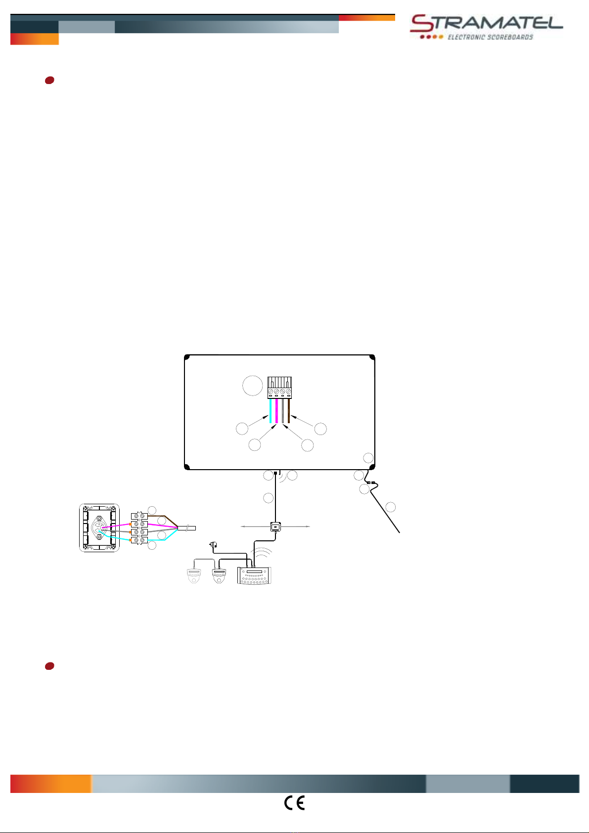
Elektrische Aufstellun - Funk esteuertes Modell
Anmerkung: die Anlage darf erst am Ende der Installation an das Stromnetz angeschlossen werden.
Für die Option zusätzliches Kabelset: Steuerkabel und Anschlußdose
Als Anschlußkabel wird ein 4-adriges Telefonkabel 6/10 verwendet.
Die Anschlußdose YBJ35 in der Nähe des Anschreibertisches befestigen.
Schließen Sie das Steuerkabel (Q) an den Steckverbinder (T) der Anzeigetafel an. Beachten Sie die Farben wie angezeigt (ANMERKUNG
– RS485: Rx und Rx- müssen unbedingt auf ein verseiltes Paar verbunden werden).
Legen Sie das Steuerkabel an. Beachten Sie dabei, dass es nicht mit dem Stromleitungskabel der Sporthalle eingezogen wird.
Schließen Sie das Steuerkabel an die Anschlußdose YBJ35 an; beachten Sie dabei die angegebenen Kabelfarben. Wenn mehrere
Anzeigetafeln zusammen verbunden sind, müssen die Kabeln parallel an die Anschlußdose gesteckt werden.
Netzkabel (P)
Anmerkung: nur das gelieferte Netzkabel verwenden. Dieses Kabel ist mit einem verdrahtetem Steckverbinder versehen und darf nicht
verändert werden.
Zwei Öffnungen (K) sind für die Durchführung des Netzkabels vorhanden: eine im Gehäuseprofil und eine andere auf der Rückseite der
Anzeigetafel.
Entfernen Sie den Kabel Pass, ziehen Sie den Steckverbinder (S) raus und verbinden Sie das Netzkabel.
Legen Sie den Steckverbinder (S) in der Anzeigetafel zurück und legen Sie den Kabel Pass wieder darüber.
Setzen Sie das Netzkabel (P) ein und stecken Sie es an das Stromnetz 100-240V an, mittels einer bipolaren Sicherung, geschützt bei 4A
(nicht mitgeliefert). Die Sicherung muss leicht zugänglich sein.
Steuerkabel (Q) : (1) = GND = blaue Ader / (2) = Rx = weiße Ader / (3) = Rx- = graue Ader / (4) = 24V = durchsichtige Ader
Ende der Installation
Die Kunststoffecken wieder anschrauben.
Die Anzeigetafel mit Hilfe der Bedienungsanleitung testen.
Multisport Serie Compact
ZI de Bel Air 44850 LE CELLIER FRANKREICH [email protected]m Tel. 33 (0)2 40 25 46 90
ID452MS3000_A - Montageanleitung 452MS3000
Seite 5
S
YBJ30
K
K
P
100-240V
50/60Hz
T
Q
SC24 SC24
1
23
4
SC24
YBJ30
T
2
4
13
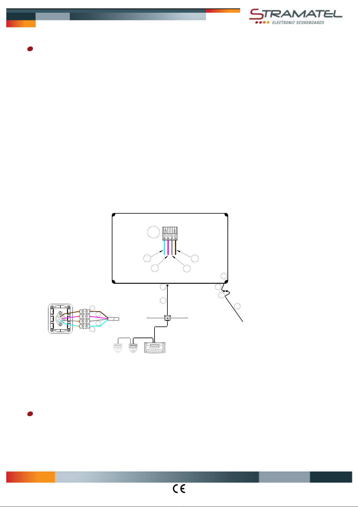
Elektrische Aufstellun – kabel esteuertes Modell
Anmerkung: die Anlage darf erst am Ende der Installation an das Stromnetz angeschlossen werden.
Steuerkabel und Anschlußdose
Als Anschlußkabel wird ein 4-adriges Telefonkabel 6/10 verwendet.
Die Anschlußdose YBJ30 in der Nähe des Anschreibertisches befestigen.
Schließen Sie das Steuerkabel (Q) an den Steckverbinder (T) der Anzeigetafel an. Beachten Sie die Farben wie angezeigt (ANMERKUNG
– RS485: Rx und Rx- müssen unbedingt auf ein verseiltes Paar verbunden werden).
Legen Sie das Steuerkabel an. Beachten Sie dabei, dass es nicht mit dem Stromleitungskabel der Sporthalle eingezogen wird.
Schließen Sie das Steuerkabel an die Anschlußdose YBJ30 an; beachten Sie dabei die angegebenen Kabelfarben. Wenn mehrere
Anzeigetafeln zusammen verbunden sind, müssen die Kabeln parallel an die Anschlußdose gesteckt werden.
Netzkabel (P)
Anmerkung: nur das gelieferte Netzkabel verwenden. Dieses Kabel ist mit einem verdrahtetem Steckverbinder versehen und darf nicht
verändert werden.
Zwei Öffnungen (K) sind für die Durchführung des Netzkabels vorhanden: eine im Gehäuseprofil und eine andere auf der Rückseite der
Anzeigetafel.
Entfernen Sie den Kabel Pass, ziehen Sie den Steckverbinder (S) raus und verbinden Sie das Netzkabel.
Legen Sie den Steckverbinder (S) in der Anzeigetafel zurück und legen Sie den Kabel Pass wieder darüber.
Setzen Sie das Netzkabel (P) ein und stecken Sie es an das Stromnetz 100-240V an, mittels einer bipolaren Sicherung, geschützt bei 4A
(nicht mitgeliefert). Die Sicherung muss leicht zugänglich sein.
Steuerkabel (Q) : (1) = GND = blaue Ader / (2) = Rx = weiße Ader / (3) = Rx- = graue Ader / (4) = 24V = durchsichtige Ader
Ende der Installation
Die Kunststoffecken wieder anschrauben.
Die Anzeigetafel mit Hilfe der Bedienungsanleitung testen.
This manual suits for next models
1
Table of contents
Languages:
Other Stramatel Accessories manuals


