Stramatel FRC Instruction manual

Outdoor
IA452FRC-IM_D - Installation FRC.docx Page 1
TECHNICAL DATA - INSTALLATION INSTRUCTIONS
Model FRC
Non-binding pictures
Outdoor
IA452FRC-IM_D - Installation FRC.docx Page 2
NOTES
Outdoor
IA452FRC-IM_D - Installation FRC.docx Page 3
Recommendations
Thank you for choosing a STRAMATEL scoreboard!
We hope that you will be fully satisfied with our product. For any information, please do not hesitate to contact us.
In order to install the scoreboard set correctly, we recommend that the instructions indicated are followed correctly, and that the
material supplied by STRAMATEL is used correctly without any alteration.
However, if extra information is required, please contact Stramatel technical service with the model reference and serial number (on
the sticker under the control console).
Any alteration made to the equipment delivered may deteriorate it and result in the cancelling of the warranty.
Caution: Installation must be performed by qualified staff and must comply with IEC 364 and national wiring regulations.
Technical data
Equipment for outdoor use.
The control console should be protected against bad weather conditions (during the operation but also when the scoreboard is not in use).
Use a soft dry cloth to clean the equipment.
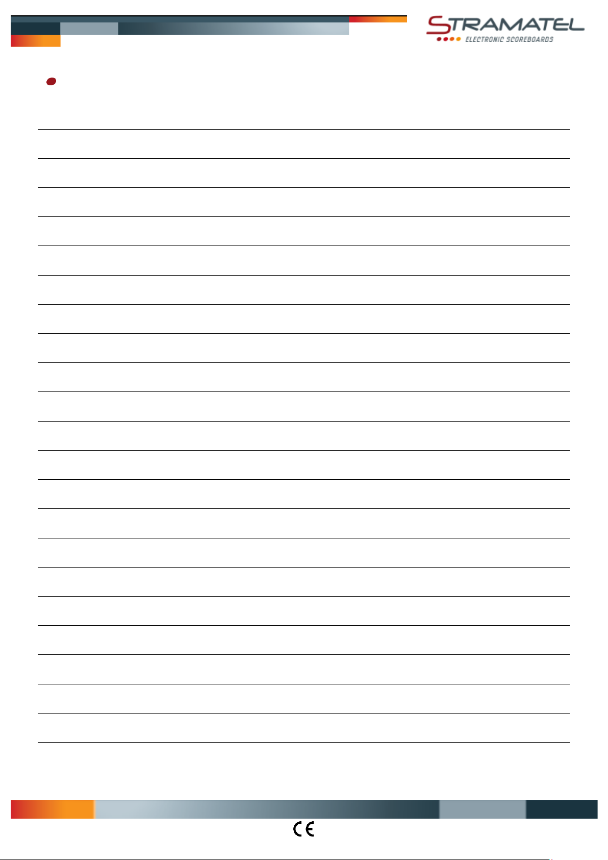
Scoreboard
Class I equipment –Must be connected to earth.
Dimensions 2500 x 1800 x 90 mm
(M1: 2500x996mm / M2: 2500x800mm)
Weight 85 kg (M1: 47 kg / M2: 38 kg)
Power supply 100-240V 50/60Hz 1,93-0,80A
Power consumed 193VA (max)
Control console –Radio controlled model
Dimensions 340 x 175 x 60 mm
Weight 790 g
Transmission frequency 863 - 870 MHz
Power supply 100-240V 50/60Hz / 12Vdc 500mA
Internal batteries NIMH 5x1,2V 1300mAh (22 hours autonomy)
Use only power supply and batteries supplied by STRAMATEL.
Control console recharge: turn off the control console. Plug the power supply into the back of the control console, then plug it into an
appropriate mains outlet (the socket should be as close as possible to the control console and must be easily accessible). Leave the
control console under constant recharge when not in use.
Control console –Cable transmission model
Dimensions 340 x 175 x 60 mm
Weight 650 g
Power supply: the control console is powered by the scoreboard. It should only be connected to the STRAMATEL system supplied.
Environment and recycling
Please help us to protect the environment by disposing of the packaging in accordance with the national regulations for waste processing.
Recycling of obsolete appliances: appliances with this label must not be disposed off with the general waste. They must be
collected separately and disposed off according to local regulations.
Outdoor
IA452FRC-IM_D - Installation FRC.docx Page 4
VE
D
G
R300
G
DD
G
DD
G
DD
G
DD
G
DD
G
DD
G
DD
G
DD
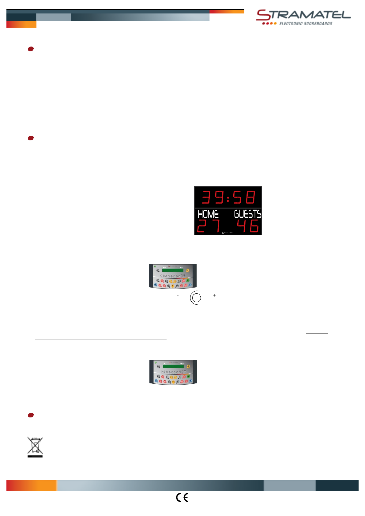
Installation on I-Beams - Before installation
The electronic elements controlling the luminous display are mounted on extractable racks (R). In order to be able to carry out any
maintenance, a clear space of at least 30 cm is necessary for the extraction of the racks. Attention: installation must be performed by
qualified staff.
The scoreboard will be fixed onto 2 vertical 180x90mm I-Beams with supplied fixing clamps (D).
Insert 2 M10 spring nuts in each fastening rail (G).
Fix 2 clamps (D) on each fastening rail (G) as mentioned below. Tighten the screws (V), then unscrew them by quarter a turn (as a first step,
the clamps should not be fully tightened).
Dimensions en mm

Outdoor
IA452FRC-IM_D - Installation FRC.docx Page 5
V
E
D
G
IPN
180x90
2500
1500 ±250
I I
I I
M2
M1
Y
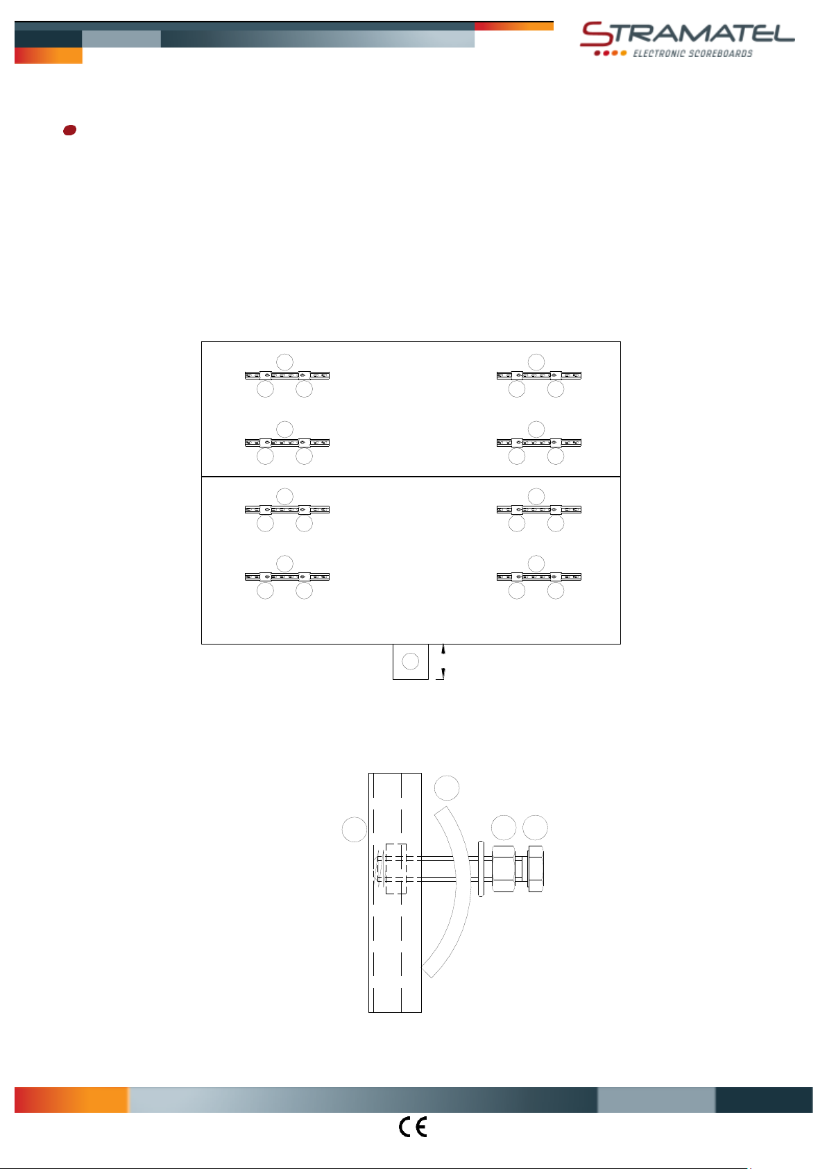
Installation on I-Beams - Scoreboard installation
In order to make the installation easier, the anchor points (I), located on the top side of the modules can be used (NB: Anchor points = insert
holes in aluminium frame). If you want to use them to lift or install the modules, replace the black plastic screws by M6x40 eyescrews
(closed rings, not supplied). Caution: the black plastic screws should not be used to lift or fix the modules (they are only dedicated to protect
the scoreboard from water intrusion).
Each module is noted with a sticker Mxx. Please strictly follow the below instructions.
Lift the module M1 and lean it against the 2 vertical 180x90mm I-Beams. Make sure the module M1 is in a horizontal position.
On each fastening rail, move the clamps as close to the I-beams as possible (the screws should imperatively touch the I-Beam to make sure
the clamps are properly fixed). Tighten the screws (V) on the fastening rails (G).
Tighten the lock nuts (E) to secure the clamps (D) on each I-Beam
Lift the module M2 above the module M1 and fix it on the I-Beams as previously instructed for the installation of the module M1.
Put the black plastic screws back into anchor points (I) of the module M2.
Plug in the connectors (Y) between the modules.

Outdoor
IA452FRC-IM_D - Installation FRC.docx Page 6
FF
1658
1702
R300
2416
2598
F' FF'
F204
600
854
F' FF'
F
30
250 2502000
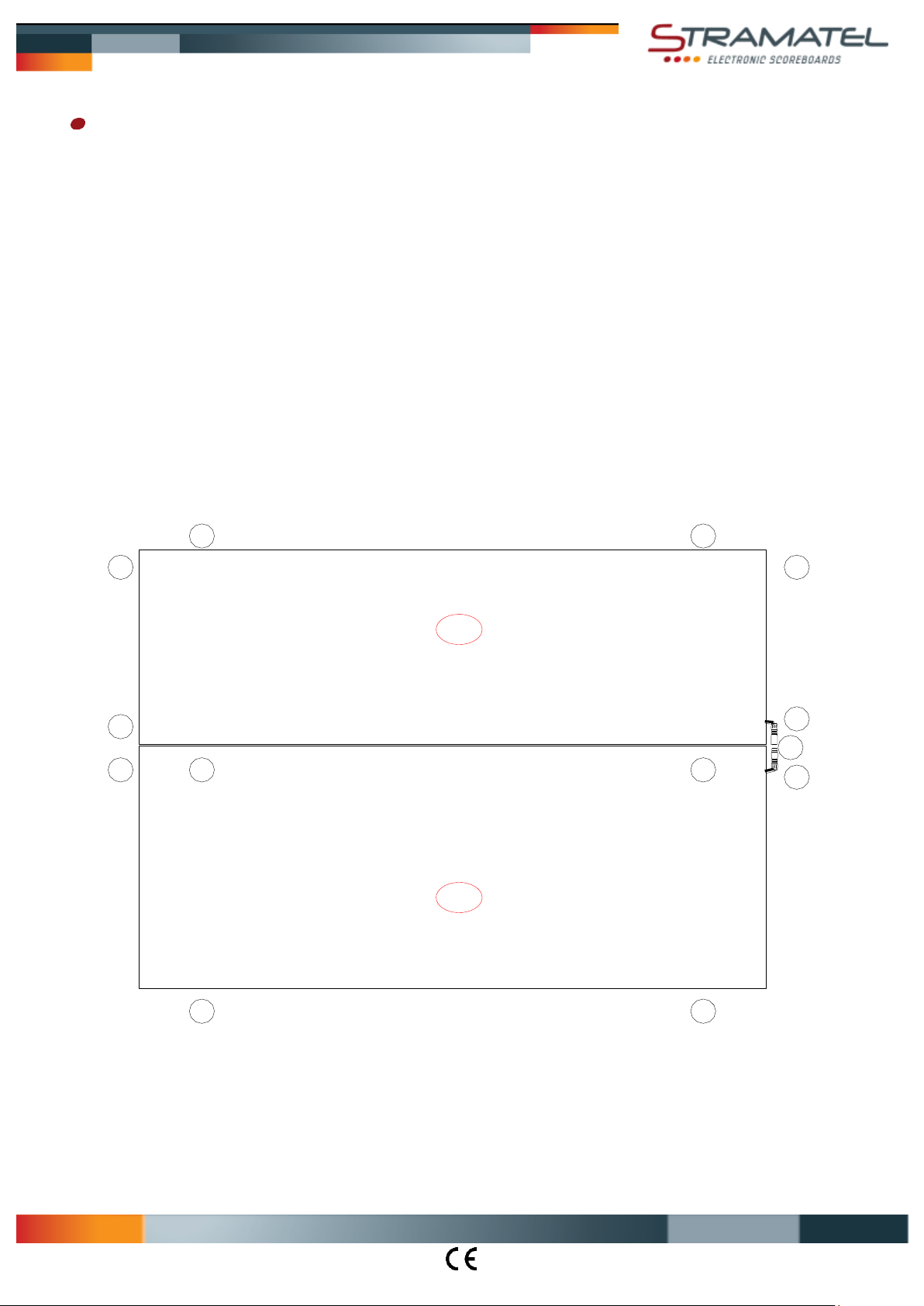
Installation on on a wall or on a support frame - Before installation
The electronic elements controlling the luminous display are mounted on extractable racks (R). In order to be able to carry out any
maintenance, a clear space of at least 30 cm is necessary for the extraction of the racks. Attention: installation must be performed by
qualified staff.
8 angle brackets are supplied to install the scoreboard (on a wall or on a support frame).
For aesthetic reasons, it is preferable to install the 6 lateral angle brackets with angle behind the scoreboard, see setting (F).
But to make the installation easier, the lateral angle brackets can also be installed with angle above the scoreboard, see setting (F').
Draw the position of the mounting points (F) or (F') onto the wall or onto the support frame according the dimensions of the diagram.
Fix the angle brackets with Ø8mm screws onto the wall or onto the support frame.
Dimensions en mm
Outdoor
IA452FRC-IM_D - Installation FRC.docx Page 7
I I
I I
I I
I
I
I
I
I I
Y
M2
M1
Installation on on a wall or on a support frame - Scoreboard installation
In order to make the installation easier, the anchor points (I), located on the top side of the modules can be used (NB: Anchor points = insert
holes in aluminium frame). If you want to use them to lift or install the modules, replace the black plastic screws by M6x40 eyescrews
(closed rings, not supplied). Caution: the black plastic screws should not be used to lift or fix the modules (they are only dedicated to protect
the scoreboard from water intrusion).
Each module is noted with a sticker Mxx. Please strictly follow the below instructions.
Lift the module M1 near the brackets.
If the pre-installed (electrical) supply is behind the scoreboard: turn off the electrical power, then connect the mains cable with the pre-
installed (electrical) supply (see chapter "Electrical installation" –"Mains cable"). The scoreboard must not be connected to mains until the
installation has been fully completed.
Place the module M1 between the brackets. Leave a space clear of at least 20mm between the module and the wall.
Fix the module M1 with the brackets by using the supplied stainless steel screws & washers Ø6mm (anchor points (I)).
Place the module M2 above the module M1. Leave a space clear of at least 20mm between the module and the wall.
Fix the module M2 with the brackets by using the supplied stainless steel screws & washers Ø6mm (anchor points (I)).
Put the black plastic screws back into anchor points (I) located on the top side of the module M2.
Plug in the connectors (Y) between the modules and slide them into the back of the scoreboard.

Outdoor
IA452FRC-IM_D - Installation FRC.docx Page 8
YBJ35
2
4
1
3
P
100-240V
50/60Hz
A
Radio controlled model - Electrical installation
Caution: the scoreboard must not be connected to mains before installation has been fully completed.
Mains cable (P)
Connect the cable (P) to 100-240V Electrical power supply which should be located in a waterproof case. The electrical power supply
should be protected via a bipolar 4A circuit breaker (not supplied). Bipolar circuit breaker must be easy to reach.
In case a cable set needs to be installed: control cable and wall junction box
Install the cable set as described in "Cable transmission model - Electrical installation".
Note: radio controlled model: +24V is not connected in the wall junction box (wall junction box YBJ35).
Control cable (Q): (1) = GND = blue wire / (2) = Rx+ = white wire / (3) = Rx- = grey wire /
(4) = +24V = transparent wire
End of the installation
Turn on the power.
Try out the scoreboard operating functions (see operating functions).
Outdoor
IA452FRC-IM_D - Installation FRC.docx Page 9
YBJ30
2
4
1
3
P
100-240V
50/60Hz
Q
1
23
4
YBJ30
T
R
B
K
T
J
B
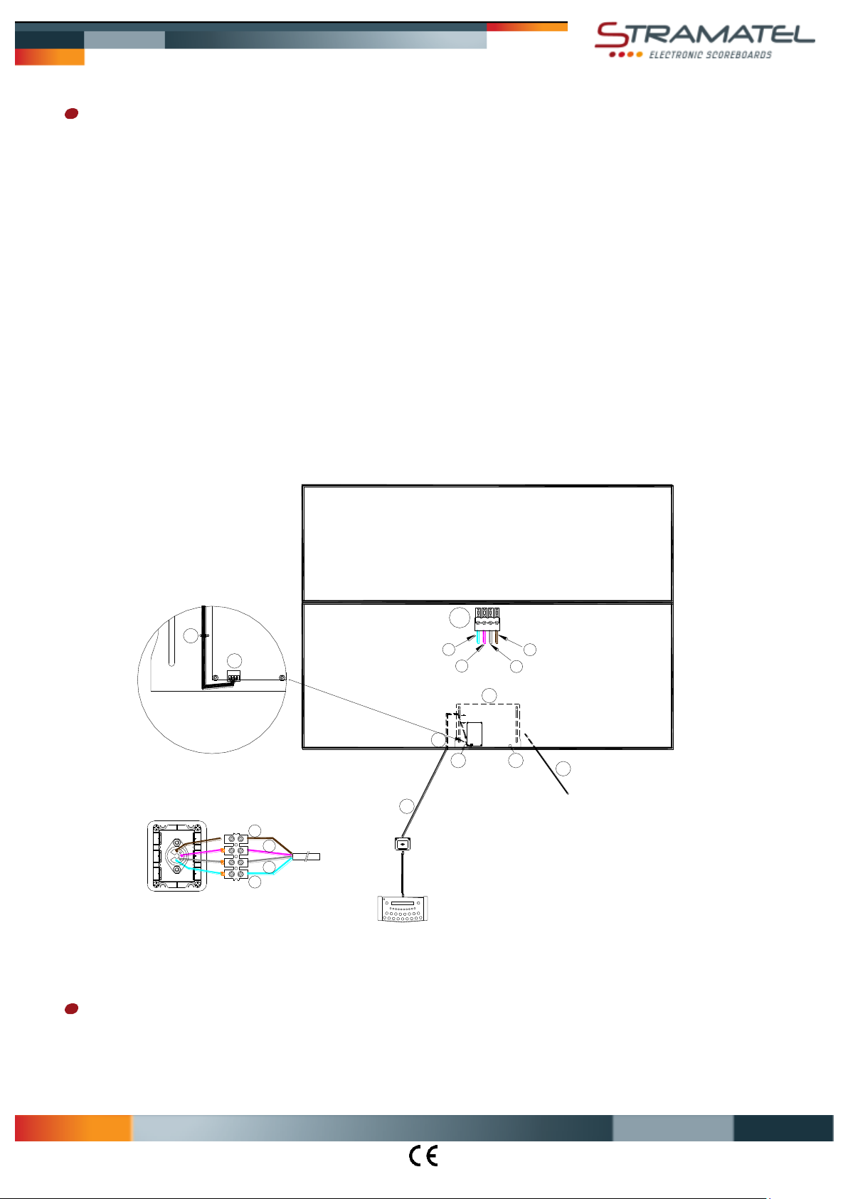
Cable transmission model - Electrical installation
Caution: the scoreboard must not be connected to mains before installation has been fully completed.
Control cable and wall junction box
The transmission cable supplied is a telephone cable: type 2 pairs 6/10ths.
Mount the wall junction box YBJ30 onto the wall close to the scoring table.
Connect the control cable (Q) on the connector (T) of the scoreboard making sure that the colour code is followed (Please note –
RS485: Rx+ and Rx- must be connected on a twisted pair).
Extract the electronic rack (R) from the scoreboard: unscrew the two nuts (B) with a 7 mm pipe spanner, then let the rack (R) slide
downwards.
Put the connector (T) inside the scoreboard through the grommet (K).
Plug the connector (T) on the electronic circuit board and fix the cable on the rack with a plastic collar (J).
Put the rack (R) back inside the scoreboard and screw the two nuts (B).
Fix the control cable into place making sure that it does not run alongside the 100-240V mains cables.
Connect the end wires into the junction box YBJ30, making sure that the colour code is followed. If several units are connected
together, their cables must be wired in parallel in the wall junction box.
Mains cable (P)
Connect the cable (P) to 100-240V Electrical power supply which should be located in a waterproof case. The electrical power supply
should be protected via a bipolar 4A circuit breaker (not supplied). Bipolar circuit breaker must be easy to reach.
Control cable (Q): (1) = GND = blue wire / (2) = Rx+ = white wire / (3) = Rx- = grey wire / (4) = +24V = transparent wire
End of the installation
Turn on the power.
Try out the scoreboard operating functions (see operating functions).

Table of contents
Other Stramatel Accessories manuals


