Strand Acclaim LED Fresnel User manual
AcclAim lED FrEsnEl
USER MANUAL
UsEr mAnUAl
www.strAnDlighting.com
AcclAim lED FrEsnEl
2
INTRODUCTION
OUR GOAL
We are committed to providing you the highest quality in customer service. Our comprehensive resources are
available to help your business succeed and ensure you get the full benefit of being a Strand customer.
TECHNICAL SUPPORT
Our Service and Support team is tasked with online and field support, repair, demo, commissioning, mainte-
nance contracts, and technical training for fixtures and systems. In addition, this team plays a large role in a
Systems sales, responsible for administering final commissioning, record-keeping, and organizing services. Refer
to the back cover of this User Manual for contacts in your region or visit www.strandlighting.com/support
CUSTOMER SERVICE
Customer Service is responsible for boxed goods and spare parts quotations, order entry and fulfilment, project
delivery, lead times, and general account management. They also manage all after sales warranty fulfilment,
RGA, and repairs invoicing in tandem with our After Sales Service & Support team. Visit our website to find a
customer service agent in your region.
ADDITIONAL DOCUMENTATION
Additional product documentation, including DMX maps, software, and photometric reports, are available for
download on our website.
For more information on installing DMX512 control systems, the following publication is available for purchase
from the United States Institute for Theatre Technology (USITT), “Recommended Practice for DMX512: A Guide
for Users and Installers, 2nd edition” (ISBN: 9780955703522).
USITT Contact Information:
USITT
315 South Crouse Avenue, Suite 200
Syracuse, New York 13210-1844 USA
Phone: 800-938-7488 or +1-315-463-6463
Fax: 866-398-7488 or +1-315-463-6525
Website: www.usitt.org
ABOUT THIS DOCUMENT
Read all instructions before installing or using this product. Retain this User Manual for future reference.
Additional product information and descriptions may be found on the product data sheet(s) which can be
downloaded from the Strand website at www.strandlighting.com.
This User Manual provides necessary information regarding safety, installation, operation and routine mainte-
nance for Strand VL2600 Series. Familiarizing yourself with this information will help you to get the most out of
your product.
WARNING: It is important to read ALL accompanying safety and installation instructions to avoid damage to
the product and potential injury to yourself or others.

UsEr mAnUAl
www.strAnDlighting.com
AcclAim lED FrEsnEl
3
SAFETY WARNINGS AND NOTICES
Read this user manual in full before attempting to install, operate or maintain the fixture to which it relates. This
user manual is intended to provide general guidance to such suitably qualified personnel. Installation and opera-
tion of the fixture are to be performed by qualified personnel only.
When using electrical equipment, basic safety precautions should always be followed including the following:
READ AND FOLLOW ALL SAFETY INSTRUCTIONS.
• For indoor, dry location use only. Do not use outdoors unless fixture is suitably IP rated.
• Use safety tether when mounting.
• Equipment should be mounted in locations and at heights where it will not be readily subjected to
tampering by unauthorized personnel.
• Not for residential use. Do not use this equipment for other than intended use.
• Note distance requirement(s) from combustible materials or illuminated objects. Do not mount near gas
or electric heaters.
• Install only in locations with adequate ventilation. Ensure sure that ventilation slots are not blocked.
• Ensure that the voltage and frequency of the power supply match the power requirements of the
fixture.
• The fixture must be earthed/grounded to the appropriate conductor.
• Do not operate fixture outside the specified ambient temperature range.
• Do not connect the fixture to any dimmer pack.
• The use of accessory equipment not recommended by the manufacturer may cause an unsafe condition
and void warranty.
• Refer service to qualified personnel. This fixture contains no user serviceable parts.
• Prior to first use, carefully inspect fixture to ensure no damage has occurred during shipping.
• Materials used in the manufacturing process can cause strong odors when the product is new. These
odors dissipate over time.
• Prior to each use, carefully inspect power cables and replace any damaged cables.
• Exterior surfaces of the luminaire will be hot during operation. Take appropriate precautions.
• Continuous use of the fixture may shorten the lifespan. Power down the fixture when not in use.
• Do not cycle power on and o repeatedly. Disconnect mains power if the fixture is not used for an
extended period.
• Clean fixtures regularly, particularly when working in a dusty environment.
• Never touch power cables or wires while the fixture is powered on.
• Avoid entangling power wires with other cables.
• In the event of a serious operating problem, immediately discontinue using the fixture.
• It is hazardous to operate luminaires without lens or shield. Shields, lenses, or ultraviolet screens shall be
changed if they have become visibly damaged to such an extent that their eectiveness is impaired, for
example, by cracks or deep scratches.
• Original packing materials can be reused for transporting the fixture.
• Do not look directly at the LED light beam while the fixture is on.
• This is a Class A product. In a domestic environment this product may cause radio interference, in which
case, the user may be required to take adequate measures.
• The light source contained in this luminaire shall only be replaced by the manufacturer or service agent
or similarly qualified person.
SAVE THESE INSTRUCTIONS.
WARNING: Refer to National Electrical Code® and local codes for cable specifications. Failure to use proper
cable can result in damage to equipment or danger to personnel.
CAUTION! Do not stare into the beam. This fixture is
categorized as Risk Group 2 (RG2). DO NOT
EXPOSE
RISK GROUP
3
RISK GROUP
2
RISK GROUP
1
RISK GROUP
EXEMPT
3.7m
(12 ft) ∞
UsEr mAnUAl
www.strAnDlighting.com
AcclAim lED FrEsnEl
4
COMPLIANCE NOTICE
FCC DECLARATION OF CONFORMITY
This equipment has been tested and found to comply with the limits for a Class A digital device pursuant to Part
15 of FCC Rules. These limits are designed to provide reasonable protection against harmful interference when
this equipment is operated in a commercial environment. This equipment generates, uses, and can radiate radio
frequency energy and, if not installed and used in accordance with Vari-Lite Strand system, service, and safety
guidelines, may cause harmful interference to radio communications.
As tested under this standard:
FCC 47CFR 15B clA*CEI
Issued:2009/10/01 Title 47 CFR Part 15 Subpart B Unintentional Radiators Class A
Operation of this equipment in a residential area is likely to cause harmful interference, in which case the user
will be required to correct the interference at his/her own expense.
EU DECLARATION OF CONFORMITY
We, Vari-Lite LLC., 10911 Petal Street, Dallas, Texas 75238, declare under our responsibility for the products
contained herein are in conformity with the essential requirements of the following European Directives and
harmonized standards:
Low Voltage Director (LVD), 2006/95/EC
EN 60589-2-17:1984+A1:1987+A2:1990 used in conjunction with 60598-1:2008/A11:2009
Electromagnetic Compatibility Directive (EMC), 2004//108/EC
EN 55022:2010, EN55024:2010

UsEr mAnUAl
www.strAnDlighting.com
AcclAim lED FrEsnEl
5
HOW TO OBTAIN WARRANTY SERVICE
A copy of the Limited Warranty card was included in the shipping package for this product.
To obtain warranty service, please contact customer service at 1-214-647-7880, or entertainment.service@
signify.com and request a Return Material Authorization (RMA) for warranty service. You will need to provide the
model and serial number of the item being returned, a description of the problem or failure and the name of the
registered user or organization. If available, you should have your sales invoice to establish the date of sale as the
beginning of the warranty period. Once you obtain the RMA, pack the unit in a secure shipping container or in its
original packing box. Be sure to clearly indicate the RMA number on all packing lists, correspondence, and ship-
ping labels. If available, please include a copy of your invoice (as proof of purchase) in the shipping container.
With the RMA number written legibly on or near the shipping address label, return the unit, freight prepaid, to:
Vari-Lite Strand
Attention: Warranty Service (RMA# ________)
10911 Petal Street
Dallas, Texas 75238
USA
As stated in the warranty, it is required that the shipment be insured and FOB our service center.
IMPORTANT! When returning products to Vari-Lite Strand for repairs (warranty or out-of-warranty) from a
country other than the USA, “Vari-Lite LLC”, must appear in the address block as the Importer of Record (IOR)
on all shipping documentation, Commercial Invoices, etc. This must be done in order to clear customs in a timely
manner and prevent returns.

UsEr mAnUAl
www.strAnDlighting.com
AcclAim lED FrEsnEl
6
FEATURES
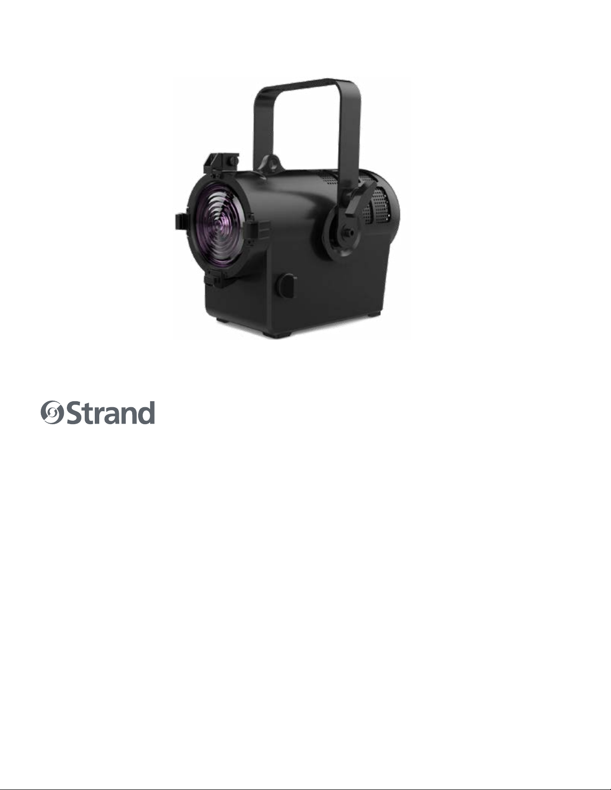
1 DESCRIPTION
AcclAim lED FrEsnEl
www.strAnDlighting.com
FEATURES AND BENEFITS
• 500W/650W-equivalent LED Fresnel – true Fresnel with superior
control and light quality than comparable PAR fixtures
• Built with the DNA of Strand - cost-eective luminaire from the original
name in theatrical lighting
• Integrated 10° to 50° manual zoom – precise beam sizing with minimal
light scatter
• Optional rotating 4-leaf barn doors – shape the beam to focus light
where you need it
• Custom LED light source and RGBL color mixing system – consistent
output and color mixing with the entire Acclaim LED Series
• Available in black or white – the perfect body color for your
application
LIMITED WARRANTY
Every Strand product is backed by a minimum 2-year limited warranty against manufacturing
defects and workmanship. Refer to the Strand Limited Warranty Card available at
www.strandlighting.com/global/support/warranty for more details.
251mm
(9.88 in)
353mm
(13.8 in)
356mm
(14 in)
253mm
(10 in)
ø156mm
(6.14 in)
190mm
(7.5 in)
Download the product datasheet from the Strand website at www.strandlighting.com for the full technical
specifications.
COMPONENTS
The document provides installation and operation instructions for the following products:
• Strand Acclaim LED Fresnel
Read all instructions before installing or using this product. Retain this manual for future reference. Additional
product information and descriptions may be found on the product specification sheet.
INCLUDED ITEMS
Each Strand Acclaim LED Fresnel luminaire includes the following items:
• Strand Acclaim LED Fresnel
• Quick Start Guide

UsEr mAnUAl
www.strAnDlighting.com
AcclAim lED FrEsnEl
7
2
INSTALLATION
1
QUICK START GUIDE
AcclAim lED FrEsnEl
9850-000840-00 rEV A 08/21
OVERVIEW
Acclaim LED Fresnel (black body) 54108-020 912400576885
Acclaim LED Fresnel (white body) 54109-020 912400576886
POWER CONNECTOR
AcclAim lED FrEsnEl
QUICK START GUIDE
(this document)
WARRANTY CARD
INCLUDED ITEMS
This document provides basic setup instructions and safety
warnings for the following product(s):
QUicK stArt
gUiDE
PowEr
connEctor
wArrAntY
cArD
INSTALLATION AND SETUP
1 2
4
3
6
5
MOUNTING
The unit should be mounted via its screw holes
on the bracket. Always ensure that the unit is
firmly fixed to avoid vibration and slipping while
operating. Always ensure that the structure to
which you are attaching the unit is secure and is
able to support a weight of 10 times of the unit’s
weight. Always use a safety cable that can hold up
to 12 times the weight of the unit when installing
the fixture.
The luminaire must be mounted by professionals.
SET UP
1 LCD display - shows menu and selected function
2 Buttons:
MENU - to select programming functions
DOWN - to go forward in selected functions
UP - to go backward in selected functions
ENTER - to confirm the selected function
3 POWER IN - connects to power supply
4 POWER OUT - connects to next fixture
5 DMX IN - 5-pin XLR cable to link the DMX
console
6 DMX OUT - 5-pin XLR cable to link next fixture
QUICK REFERENCE DMX MAPS
DMX
CHANNEL PARAMETER
1 Intensity (16-bit high)
2 Strobe
3 Red (16-bit high)
4 Green (16-bit high)
5 Blue (16-bit high)
6 Lime (16-bit high)
DMX
CHANNEL PARAMETER
1 Intensity (16-bit high)
2 Intensity (16-bit low)
3 Strobe
4 Red (16-bit high)
5 Red (16-bit low)
6 Green (16-bit high)
7 Green (16-bit low)
8 Blue (16-bit high)
9 Blue (16-bit low)
10 Lime (16-bit high)
8-BIT CHANNEL MODE
16-BIT CHANNEL MODE
BARNDOOR INSTALLATION
Compatible Strand barndoors are listed in the table below.
ACCLAIM LED FRESNEL 4 LEAF BARNDOOR (Black) 912400576893 64511-010
ACCLAIM LED FRESNEL 4 LEAF BARNDOOR (White) 912400576894 64511-110
To install barndoor:
Step 1. Open the activity claw.
Step 1. Snap the barndoor into the luminaire and close the activity claw as shown.
MECHANICAL ZOOM ADJUSTMENT
To adjust the mechanical zoom:
Step 1. Pinch the zoom knobs on both sides.
Step 2. Press the zoom knobs to the inside and rotate the knobs to achieve the desired beam edge as shown.

UsEr mAnUAl
www.strAnDlighting.com
AcclAim lED FrEsnEl
8
CONNECTING DATA AND POWER
A maximum of 32 luminaires may be connected in any one DMX data link.
A maximum of 9 luminaires may be connected in 120V, 60Hz.
A maximum of 16 luminaires may be connected in 230V, 50Hz.
NOTE: This maximum limit applies to the luminaire “daisy chain” only. Your system or console may require few-
er luminaires on a single data link path. Consult your console documentation for more information.
To connect power and data:
Step 1. Connect data cable from console to first luminaire in chain at DATA IN connector.
Step 2. If required, connect additional data cables from DATA THRU connectors to DATA IN connectors of
remaining luminaires in link.
Step 3. At last luminaire in link, install male termination connector at DATA THRU connector. (Luminaires and
other devices on the same DMX chain may not function properly without termination.)
Step 4. Connect AC Input Cable connector to power input source.
Step 5. Dress AC input and data cables and secure them so that they will not interfere with luminaire head
and yoke movement.

UsEr mAnUAl
www.strAnDlighting.com
AcclAim lED FrEsnEl
9
3 MENU OPERATION
CONTROL PANEL
Press the MENU button to select any functions, until the required function is shown in the display. Select the
desired function by pressing ENTER, which will cause the display to blink. Use the UP and DOWN button to
change the mode. Once the required mode has been selected, press the ENTER button to accept the selection,
otherwise after a period of one minute wait, the the menu will return automatically to the main functions, with-
out any changes having been made. Return to the main functions without making any changes by pressing the
MENU button.
1
QUICK START GUIDE
AcclAim lED FrEsnEl
9850-000840-00 rEV A 08/21
OVERVIEW
Acclaim LED Fresnel (black body) 54108-020 912400576885
Acclaim LED Fresnel (white body) 54109-020 912400576886
POWER CONNECTOR
AcclAim lED FrEsnEl
QUICK START GUIDE
(this document)
WARRANTY CARD
INCLUDED ITEMS
This document provides basic setup instructions and safety
warnings for the following product(s):
QUicK stArt
gUiDE
PowEr
connEctor
wArrAntY
cArD
INSTALLATION AND SETUP
1 2
4
3
6
5
MOUNTING
The unit should be mounted via its screw holes on
the bracket. Always ensure that the unit is firmly
fixed to avoid vibration and slipping while operating.
Always ensure that the structure to which you are
attaching the unit is secure and is able to support
a weight of 10 times of the unit’s weight. Always
use a safety cable that can hold up to 12 times the
weight of the unit when installing the fixture. The
luminaire must be mounted by professionals.
CONTROL PANEL
1
LCD display - shows menu and selected function
2
Buttons:
MENU - to select programming functions
DOWN - to go forward in selected functions
UP - to go backward in selected functions
ENTER - to confirm the selected function
3
POWER IN - connects to power supply
4
POWER OUT - connects to next fixture
5
DMX IN - 5-pin XLR cable to link the DMX
console
6
DMX OUT - 5-pin XLR cable to link next fixture
QUICK REFERENCE DMX MAPS
DMX
CHANNEL PARAMETER
1 Intensity (16-bit high)
2 Strobe
3 Red (16-bit high)
4 Green (16-bit high)
5 Blue (16-bit high)
6 Lime (16-bit high)
DMX
CHANNEL PARAMETER
1 Intensity (16-bit high)
2 Intensity (16-bit low)
3 Strobe
4 Red (16-bit high)
5 Red (16-bit low)
6 Green (16-bit high)
7 Green (16-bit low)
8 Blue (16-bit high)
9 Blue (16-bit low)
10 Lime (16-bit high)
8-BIT CHANNEL MODE
16-BIT CHANNEL MODE
SHORTCUT KEYS
BUTTON
COMBINATION FUNCTION
MENU + ENTER Factory defaults
ENTER + UP Turns the fixture on at full output
ENTER + DOWN Toggles through Standard, Studio, and Whisper modes
UP + DOWN Inverts display

UsEr mAnUAl
www.strAnDlighting.com
AcclAim lED FrEsnEl
10
LEVEL 1 LEVEL 2 LEVEL 3 LEVEL 4 LEVEL 5 LEVEL 6 DEFAULT
DMX
Address 001~512
DMX Mode 8 - Bit (Default)
16 - Bit
Data
Ch 1 - Intensity XXX (Value)
Ch 2 - Intensity Fine XXX (Value)
……All functions
DMX Fail DMX Hold (Default)
Blackout
Manual
Red 0-255 (Default - 0)
Green 0-255 (Default - 0)
Blue 0-255 (Default - 0)
Lime 0-255 (Default - 0)
Settings
LED
Dimming Curve
Square Law (Default)
S Curve
Linear
Output Mode
Standard (Default)
Studio
Whisper
Color Calibration On
O (Default)
Fan Mode On
Auto (Default)
Refresh Rate
500Hz
1000Hz
1500Hz (Default)
2000Hz
2500Hz
3000Hz
3500Hz
4000Hz
Display On Time Auto (30 seconds since last press) (Default)
On
Reset Defaults Are You Sure?
Service
Status (No Errors... or displays a list of errors) Give list of fixture errors
Diagnostics Fan Check Give fans speeds
Temp Give LED / Fixture temperatures
Version VXXX
Fixture Hours Gives Fixture run time hours / LED hours
Cross load
(Software) Are You Sure? Send
Password (2606)
White Balance
Red
Green
Blue
Lime
Reset to Defaults (Reset to White Balance)
Change Model
Zoomspot
PLE
Fresnel
Cyc

UsEr mAnUAl
www.strAnDlighting.com
AcclAim lED FrEsnEl
11
NOTE: Not all menu options are available for every fixture.
DMX MENU
Choose DMX, press the ENTER button to confirm, use the UP/DOWN button to choose from options listed.
ADDRESS
Choose Address, press the ENTER button to confirm. Use the UP/DOWN button to select range of values. Press
the ENTER button to store. Press the MENU button to return to previous menu or let the unit idle one minute to
exit.
DMX MODE
Choose DMX Mode, press the ENTER button to confirm. Use the UP/DOWN button to select mode. Press the
ENTER button to store. Press the MENU button to return to previous menu or let the unit idle one minute to exit.
DATA
Choose Data, press the ENTER button to confirm. Use the UP/DOWN button to select option. Choose Ch1 –
Intensity xxx(value), Ch2 – Intensity Fine xxx(Value), …. All functions, press the ENTER button to store. Press the
MENU button to return to previous menu or let the unit idle one minute to exit menu mode.
DMX FAIL
To select DMX Fail, press the ENTER button to confirm. Use the UP/DOWN button to select DMX Hold or
Blackout, press the ENTER button to store. Press the MENU button back to the last menu or let the unit idle one
minute to exit menu mode.
MANUAL MENU
To select Manual, press the ENTER button to confirm, use the UP/DOWN button to select Red, Green, Blue and
Lime. Use the UP/DOWN button to adjust the value from 0 to 255, press the ENTER button to store. Press the
MENU button back to the last menu or let the unit idle one minute to exit menu mode.
SETTINGS MENU
Choose Settings, press the ENTER button to confirm, use the UP/DOWN button to choose from options shown
on screen.
LED
Choose LED, press the ENTER button to confirm. Use the UP/DOWN button to select an option. Press the EN-
TER button to store. Press the MENU button to return to previous menu or let the unit idle one minute to exit
menu mode.
DIMMING CURVE
To Choose Dimming Curve, press the ENTER button to confirm. Use the UP/DOWN button to Choose Square
Law Curve, S Law Curve or Linear Law Curve, press the ENTER button to store. Press the MENU button to return
to previous menu or let the unit idle one minute to exit menu mode.
DMX OUTPUT
0 255
100
LIGHT OUTPUT
DMX OUTPUT
0 255
100
LIGHT OUTPUT
DMX OUTPUT
0 255
100
LIGHT OUTPUT
LINEAR S-CURVE SQUARE LAW

UsEr mAnUAl
www.strAnDlighting.com
AcclAim lED FrEsnEl
12
OUTPUT MODE
Choose Output Mode, press the ENTER button to confirm. Use the UP/DOWN button to select Standard, Studio,
or Whisper. Press the MENU button to return to previous menu.
COLOR CALIBRATION
Choose Color Cal, press the ENTER button to confirm. Use the UP/DOWN button to Choose ON or OFF. Press the
MENU button to return to previous menu.
FAN MODE
Select Fan Mode, press the ENTER button to confirm. Use the UP/DOWN button to select On or Auto, press the
ENTER button to store. Press the MENU button back to the last menu or let the unit idle one minute to exit menu
mode.
REFRESH RATE
Select Refresh Rate, press the ENTER button to confirm. Use the UP/DOWN button to select 500Hz, 1000Hz,
1500Hz, 2000Hz, 2500Hz, 3000Hz, 3500Hz, 4000Hz, press the ENTER button to store. Press the MENU button
back to the last menu or let the unit idle one minute to exit menu mode.
DISPLAY ON TIME
To select Display On Time, press the ENTER button to confirm. Use the UP/DOWN button to select Auto(30 sec-
onds since last press) or On, press the ENTER button to store. Press the MENU button back to the last menu or let
the unit idle one minute to exit menu mode.
RESET DEFAULTS
To select Reset Defaults, press the ENTER button to confirm, Are You Sure? will show on the display, press the EN-
TER button to store. Press the MENU button back to the last menu or let the unit idle one minute to exit menu
mode.
SERVICE
SERVICE MENU
To select Service, press the ENTER button to confirm, use the UP/DOWN button to select Status, Diagnostics,
Version, Fixture Hours, Crossload(Software) and Password(2606).
STATUS
To select Status, press the ENTER button to confirm, No Errors or a list of errors will show on the display, press
the MENU button back to exit.
DIAGNOSTICS
To select Diagnostics, press the ENTER button to confirm. Use the UP/DOWN button to select Fan Check or Temp,
press the ENTER button to store. Press the MENU button back to the last menu or let the unit idle one minute to
exit menu mode.
VERSION
To select Version, press the ENTER button to confirm, Version will show on the display, press the MENU button
back to exit.
FIXTURE HOURS
To select Fixture Hours, press the ENTER button to confirm, Fixture Hours will show on the display, press the
MENU button back to exit.
CROSSLOAD(SOFTWARE)
Select Crossload(Software), press the ENTER button to confirm, Are You Sure? will show on the display, press the
ENTER button to store. Press the MENU button back to the last menu or let the unit idle one minute to exit menu
mode.

UsEr mAnUAl
www.strAnDlighting.com
AcclAim lED FrEsnEl
13
NOTE: Incoming DMX must be removed from the fixture or software crossload will not be activated.
PASSWORD
Select Password(2606), press the ENTER button to confirm. Use the UP/DOWN button to select White Balance
or Change Mode, press the ENTER button to store. Press the MENU button back to the last menu or let the unit
idle one minute to exit menu mode.
WHITE BALANCE
To select White Balance, press the ENTER button to confirm. Use the UP/DOWN button to select Red, Green,
Blue, Lime or Reset to Defaults (Reset to White Balance), press the ENTER button to store. Press the MENU
button back to the last menu or let the unit idle one minute to exit menu mode.
CHANGE MODE
To select Change Mode, press the ENTER button to confirm. Use the UP/DOWN button to select Zoomspot, PLE,
Fresnel or Cyc, press the ENTER button to store. Press the MENU button back to the last menu or let the unit
idle one minute to exit menu mode.

UsEr mAnUAl
www.strAnDlighting.com
AcclAim lED FrEsnEl
14
The fixture can be operated by DMX controller. The following tables assumes a DMX start address of 1. When
a dierent starting address is used, this address becomes channel 1 function and other functions follow in se-
quence.
4 DMX MAPPING
TABLE 1. 8-BIT MODE (DEFAULT)
DMX
CHANNEL PARAMETER DEFAULTS RANGE DMX DESCRIPTION
1Intensity
(16-bit high) 00 - 255 16-bit intensity (dimmer) control
2Strobe 0
0Open
1 - 255 Strobe speed Slow>>>>>>>>>>>>>>>>>>>Fast
(Rate TBC) XX Hz>>>>>>>>>>>>>>>>>XX Hz
3Red (16-bit high) 255 0 - 255 Red LED Output level
4Green (16-bit high) 255 0 - 255 Green LED Output level
5Blue (16-bit high) 255 0 - 255 Blue LED Output level
6Lime (16-bit high) 255 0 - 255 Lime LED Output level
TABLE 2. 16-BIT MODE
DMX
CHANNEL PARAMETER DEFAULTS RANGE DMX DESCRIPTION
1Intensity
(16-bit high) 00 - 255 16-bit intensity (dimmer) control
2Intensity
(16-bit low) 00 - 65535 Open
3Strobe 00Open
1 - 255 Strobe speed Slow>>>>>>>>>>>>>>>>>>>Fast
4Red (16-bit high) 255 0 - 255
(16-bit) Red LED output level
5Red (16-bit low) 65535 0 - 65535
(16-bit)
6Green (16-bit high) 255 0 - 255
(16-bit) Green LED output level
7Green (16-bit low) 65535 0 - 65535
(16-bit)
8Blue (16-bit high) 255 0 - 255
(16-bit) Blue LED output level
9Blue (16-bit low) 65535 0 - 65535
(16-bit)
10 Lime (16-bit high) 255 0 - 255
(16-bit) Lime LED output level
11 Lime (16-bit low) 65535 0 - 65535
(16-bit)
UsEr mAnUAl
www.strAnDlighting.com
AcclAim lED FrEsnEl
15
COLOR PRESET
R G B L CCT TARGET CRI (RA)
255 014 206 2700K 82.3
255 033 255 3200K 84.4
255 44 73 255 4500K 86
255 88 119 255 5600K 85.8
255 127 170 255 6500K 85.2
255 161 204 255 7000K 84.4
255 255 255 255 7472K 82.2
UsEr mAnUAl
www.strAnDlighting.com
AcclAim lED FrEsnEl
16
5 RDM PARAMETER IDs
Remote Device Management (RDM) is a protocol enhancement to USITT DMX512 that allows bi-directional com-
munication between a lighting or system controller and attached RDM compliant devices over a standard DMX
line. This protocol will allow configuration, status monitoring, and management of these devices in such a way
that does not disturb the normal operation of standard DMX512 devices that do not recognize the RDM protocol.
ACCLAIM LED FRESNEL RDM PRODUCT PARAMETER IDS
Model ID Manufacturer Vendor ID Model Description Product Category
0x0214 Strand 0x736C Acclaim LED Fresnel 0x0101
The table on the following pages outlines and describes all the RDM parameters IDs associated with the
Acclaim LED Fresnel.
UsEr mAnUAl
www.strAnDlighting.com
AcclAim lED FrEsnEl
17
GET
ALLOWED
SET
ALLOWED RDM PARAMETER IDS VALUE COMMENT ESTA
STANDARD
REQUIRED /
IMPLEMENTED DMX / UI DESCIPTION
Category - Network Management
DISC_UNIQUE_BRANCH 0x0001 X X
DISC_MUTE 0x0002 X X
DISC_UN_MUTE 0x0003 X X
XPROXIED_DEVICES 0x0010
XPROXIED_DEVICES_COUNT 0x0011
X X COMMS_STATUS 0x0015
Category - Status Collection
XQUEUED_MESSAGE 0x0020
XSTATUS_MESSAGES 0x0030 XStatus
XSTATUS_ID_DESCRIPTION 0x0031 X
XCLEAR_STATUS_ID 0x0032
X X SUB_DEVICE_STATUS_REPORT_THRESHOLD 0x0033
Category - RDM Information
XSUPPORTED_PARAMETERS 0x0050 X X
XPARAMETER_DESCRIPTION 0x0051 X X
Category - Product Information
XDEVICE_INFO 0x0060 X X
XPRODUCT_DETAIL_ID_LIST 0x0070
XDEVICE_MODEL_DESCRIPTION 0x0080 X
XMANUFACTURER_LABEL 0x0081 X
X X DEVICE_LABEL 0x0082 X
X X FACTORY_DEFAULTS 0x0090 XReset Defaults
XLANGUAGE_CAPABILITIES 0x00A0
X X LANGUAGE 0x00B0
XSOFTWARE_VERSION_LABEL 0x00C0 X X Version
XBOOT_SOFTWARE_VERSION_ID 0x00C1
XBOOT_SOFTWARE_VERSION_LABEL 0x00C2
UsEr mAnUAl
www.strAnDlighting.com
AcclAim lED FrEsnEl
18
GET
ALLOWED
SET
ALLOWED RDM PARAMETER IDS VALUE COMMENT ESTA
STANDARD
REQUIRED /
IMPLEMENTED DMX / UI DESCIPTION
Category - DMX512 Setup
X X DMX_PERSONALITY 0x00E0 XDMX Mode
XDMX_PERSONALITY_DESCRIPTION 0x00E1 X
X X DMX_START_ADDRESS 0x00F0 X X Address
XSLOT_INFO 0x0120 X
XSLOT_DESCRIPTION 0x0121 X
XDEFAULT_SLOT_VALUE 0x0122 X
Category – Sensors 0x02xx USE
XSENSOR_DEFINITION 0x0200 X
X X SENSOR_VALUE 0x0201 Fan Speed and
Temperatures
XDiagnostics
XRECORD_SENSORS 0x0202
Category - Dimmer Settings 0x03xx - FUTURE USE
X X Dimmer Curve 0x0343 X
X Dimmer Curve Description 0x0344 X
X X Modulation Frequency 0x0347 X
X Modulation Frequency Description 0x0348 X
Category - Power / Lamp Settings 0x04xx
X X DEVICE_HOURS 0x0400 XFixture Hours
X X LAMP_HOURS 0x0401
X X LAMP_STRIKES 0x0402
X X LAMP_STATE 0x0403
X X LAMP_ON_MODE 0x0404
X X DEVICE_POWER_CYCLES 0x0405
Category - Display Settings 0x05xx
X X DISPLAY_INVERT 0x0500
X X DISPLAY_LEVEL 0x0501
Category - Configuration 0x06xx
X X PAN_INVERT 0x0600
X X TILT_INVERT 0x0601
X X PAN_TILT_SWAP 0x0602
X X REAL_TIME_CLOCK 0x0603
UsEr mAnUAl
www.strAnDlighting.com
AcclAim lED FrEsnEl
19
GET
ALLOWED
SET
ALLOWED RDM PARAMETER IDS VALUE COMMENT ESTA
STANDARD
REQUIRED /
IMPLEMENTED DMX / UI DESCIPTION
Category - DMX512 Setup
X X DMX_PERSONALITY 0x00E0 XDMX Mode
XDMX_PERSONALITY_DESCRIPTION 0x00E1 X
X X DMX_START_ADDRESS 0x00F0 X X Address
XSLOT_INFO 0x0120 X
XSLOT_DESCRIPTION 0x0121 X
XDEFAULT_SLOT_VALUE 0x0122 X
Category – Sensors 0x02xx USE
XSENSOR_DEFINITION 0x0200 X
X X SENSOR_VALUE 0x0201 Fan Speed and
Temperatures
XDiagnostics
XRECORD_SENSORS 0x0202
Category - Dimmer Settings 0x03xx - FUTURE USE
X X Dimmer Curve 0x0343 X
X Dimmer Curve Description 0x0344 X
X X Modulation Frequency 0x0347 X
X Modulation Frequency Description 0x0348 X
Category - Power / Lamp Settings 0x04xx
X X DEVICE_HOURS 0x0400 XFixture Hours
X X LAMP_HOURS 0x0401
X X LAMP_STRIKES 0x0402
X X LAMP_STATE 0x0403
X X LAMP_ON_MODE 0x0404
X X DEVICE_POWER_CYCLES 0x0405
Category - Display Settings 0x05xx
X X DISPLAY_INVERT 0x0500
X X DISPLAY_LEVEL 0x0501
Category - Configuration 0x06xx
X X PAN_INVERT 0x0600
X X TILT_INVERT 0x0601
X X PAN_TILT_SWAP 0x0602
X X REAL_TIME_CLOCK 0x0603
GET
ALLOWED
SET
ALLOWED RDM PARAMETER IDS VALUE COMMENT ESTA
STANDARD
REQUIRED /
IMPLEMENTED DMX / UI DESCIPTION
Category - Control 0x10xx
X X IDENTIFY_DEVICE 0x1000 X X
XRESET_DEVICE 0x1001 X
X X POWER_STATE 0x1010
X X PERFORM_SELFTEST 0x1020 All Test, Pan/Tilt,
Encoder
XSELF_TEST_DESCRIPTION 0x1021
XCAPTURE PRESET 0x1030 See E1-20_2010a
X X PRESET PLAYBACK 0x1031 Table A-7 defines
ESTA Reserved Future RDM 0x7FE0-
0x7FFF
Manufacturer-Specific PIDs 0x8000-
0xFFDF
X X Output Power Mode 0x8A97
Value range
depends on options
(Standard, Studio,
etc)
X
LED Output Mode
X X Pan/Tilt Feedback (On/O) 0x8AD3
X X Display On Time 0x8AA0 Value range
depends on options XDisplay On Time
X X LED Dimmer Curve 0x8AA1 Value range
depends on options
LED Dimming Curve
X X Pan Tilt Movement (On/O) 0x8AA2
X X Head Motor Movement (On/O) 0x8AA3
X X Auto Shutdown Mode 0x8AA4 Value range
depends on options
X X LED Hours 0x8AA5
X X Dim Snap (On/O) 0x8AA6
X X Color Snap (On/O) 0x8AA7
X X Auto Fan Mode (On/O) 0x8AA8 LED Fan Mode
X X Gamma Shift 0x8AA9 Value range
depends on options
X X Tungsten Dimming (On/O) 0x8AA10
X X CTB Correction (On/O) 0x8AA11
UsEr mAnUAl
www.strAnDlighting.com
AcclAim lED FrEsnEl
20
GET
ALLOWED
SET
ALLOWED RDM PARAMETER IDS VALUE COMMENT ESTA
STANDARD
REQUIRED /
IMPLEMENTED DMX / UI DESCIPTION
Category - Control 0x10xx (continued)
X X LED Refresh Rate 0x8AA12 Value range
depends on options LED Refresh Rate
X X Side Hang (On/O) 0x8AA13
X X Focus Track (On/O) 0x8AA14
XControl Signel select DMX only/ARtNET (On/O) 0x8AA15
XRecalibrate Fixture (Level) 0x8AA16 dierent levels (all,
position, color, etc)
X X DMX Fail (Hold, Blackout, GOTO Preset) 0x8AA17 DMX Fail
X X ArtNet Universe 0x8AA18
X X ArtNet Net 0x8AA19
X X ArtNet Sub-Net 0x8AA20
X X ArtNet Ethernet IP 0x8AA21
X X ArtNet Ethernet Sub-Net Mask 0x8AA22
X X Manual PRESET Playback Power Up Preset 0x8AA23
X X Manual PRESET Playback Preset Intensity 0x8AA24
X X Manual PRESET Playback Priority 0x8AA25
X X Manual PRESET Playback Power Up? 0x8AA26
X X LED Color Calibration (On/O) 0x8AA27 XLED Color Calibration
Table of contents
Other Strand Dj Equipment manuals

Strand
Strand Acclaim LED PLE User manual

Strand
Strand LEKO LED PROFILE FULL COLOR User manual

Strand
Strand VL2600 Series User manual

Strand
Strand ACCLAIM LED CYC User manual

Strand
Strand Aurora 12 LED Strip User manual

Strand
Strand NEO COMPACT 10 User manual

Strand
Strand CANTATA LED FRESNEL User manual

Strand
Strand CODA LED CYC User manual

Strand
Strand NEO COMPACT 10 PC WING User manual

Strand
Strand Fresnelite 12081 User manual


