Strand VISION.NET Series User manual

1
QUICK START GUIDE
65710 WWW.STRANDLIGHTING.COM
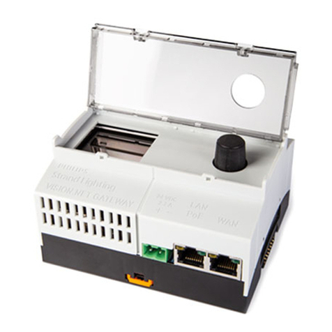
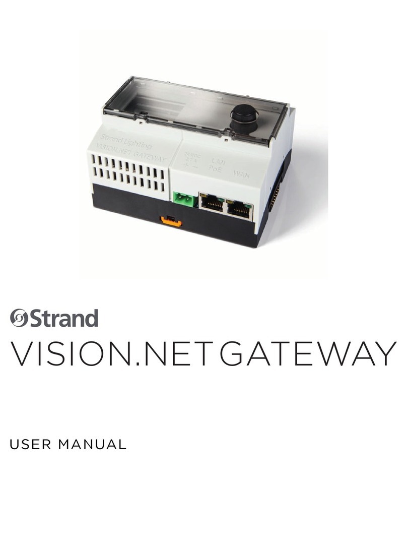
VISION.NET GATEWAY
SERIES
65710 Vision.Net Gateway
65730 Vision.Net Interface Gateway Module
This document provides basic setup instructions and safety warnings for the following product(s):
INSTALLATION AND SETUP
POWER REQUIREMENTS
Vision.Net Gateway may be powered via either a Power over Ethernet (PoE) supply or from an external DC pow-
er supply connected via a set of screw terminals.
NOTE: DC and PoE power connections will not operate as a redundant power solution.
A CR1225 backup battery (pre-installed) is used for the real-time clock. External modules are powered from the
Gateway module through the DIN rail bus system, and do not require their own power supply.
The Gateway draws up to 40W of power, depending on the configuration of modules added. For PoE supplies it
is best to use an 803.2bt class7-8 high power source, however in some circumstances, it may be powered from
an 803.2af PoE+ supply. Consult the table below for further information to select the right options.
PoE REQUIREMENTS
COMBINATION PoE PSE TYPE DESCRIPTION
Gateway standalone 802.3af 12W @ the gateway
Gateway + 1 VN 802.3bt class 5 or higher 40W @ the gateway
MOUNTING / INSTALLATION
WARNING! Do not power the system until all modules are placed and
connected as described in the steps below.
To mount Vision.Net Gateway and other modules:
Step 1. Unpack module(s), taking precautions against ESD.
Step 2. Place the DIN rail bus connector into the DIN rail.
Step 3. Mount Vision.net Gateway module on DIN rail, taking care to ori-
ent the modules as shown. Take special care aligning, to prevent
bending the pins
• If used, mount accessory modules close to Vision.Net Gate-
way module to ensure good contact
• Place end-caps on the DIN rail bus to prevent
dirt contamination on the pins
Step 4. If required, install DIN rail clamps (not supplied) as
necessary.
To remove modules from DIN rail:
Step 1. Slide any modules apart
Step 2. Insert flat head screw driver against the tabs to
release. The DIN rail bus may; in some circum-
stances, remain attached to the rail and can be
removed by releasing the small clips, if required.
SERIAL USB
WAN
LAN
−
24 VDC
2.7 A
+PoE
VISION.NET GATEWAY
+
D
–
D
+–+–+–
VISION.NET INTERFACE
GATEWAY MODULE

2
WARNINGS AND NOTICES
When using electrical equipment, basic safety precautions should always
be followed including the following:
READ AND FOLLOW ALL SAFETY INSTRUCTIONS.
• For indoor, dry locations use only. Do not use outdoors.
• Do not mount near gas or electric heaters.
• Equipment should be mounted in locations and at heights where it will
not readily be subjected to tampering by unauthorized personnel.
• The use of accessory equipment not recommended by the
manufacturer may cause an unsafe condition.
• Not for residential use. Do not use this equipment for other than
intended use.
• Refer service to qualified personnel.
SAVE THESE INSTRUCTIONS.
WARNING: You must have access to a main circuit breaker or other
power disconnect device before installing any wiring. Be sure that power
is disconnected by removing fuses or turning the main circuit breaker o
before installation. Installing the device with power on may expose you to
dangerous voltages and damage the device. A qualified electrician must
perform this installation.
WARNING: Refer to National Electrical Code® and local codes for cable
specifications. Failure to use proper cable can result in damage to equip-
ment or danger to personnel.
WARNING: This equipment is intended for installation in accordance
with the National Electric Code® and local regulations. It is also intended
for installation in indoor applications only. Before any electrical work is
performed, disconnect power at the circuit breaker or remove the fuse to
avoid shock or damage to the control. It is recommended that a qualified
electrician perform this installation.
CUSTOMER SERVICE
If you have any questions regarding this product, please contact Customer
Service at +1-214-647-7880 or via e-mail at entertainment.service@
signify.
LIMITED 2-YEAR WARRANTY
Strand oers a two-year limited warranty on its control products against
defects in materials or workmanship from the date of delivery. A copy of
Strand two-year limited warranty containing specific terms and conditions
can be obtained from the Strand website at www.strandlighting.com or by
contacting your local Strand oce.
2000851
ASIA
Room 1201, Freetown Tower D
E 3rd Ring Rd S, 58
Chaoyang Qu
Beijing Shi, China
Tel: +8610-58674776
Fax: +8610-58674775
B-1-27, Dataran Cascades, No. 13A
Jalan PJU 5/1
Kota Damansara PJU 5
47810 Petaling Jaya
Selangor, Malaysia
Tel: +60 3-7611 7302
©2019 Signify Holding. All rights reserved. All trademarks are
owned by Signify Holding or their respective owners. The
information provided herein is subject to change, without
notice. Signify does not give any representation or warranty
as to the accuracy or completeness of the information
included herein and shall not be liable for any action in
reliance thereon. The information presented in this document
is not intended as any commercial offer and does not form
part of any quotation or contract, unless otherwise agreed by
Signify. Data subject to change.
AMERICAS
10911 Petal Street
Dallas, TX 75235
Tel: +1 214-647-7880
Fax: +1 214-647-8039
OFFICES
STRAND
EUROPE
Rondweg Zuid 85
Winterswijk 7102 JD
Netherlands
Tel: +31 543-542516
Fax: +31 543-542513
24 Sovereign Park
Coronation Road
Park Royal, London
NW10 7QP
United Kingdom
Tel: +44 020 8965 3209
CONFIGURATION
To configure Gateway modules:
Step 1. Set address using a small flat head screwdriver to flip DIP
switches. Be sure assigned addresses are unique.
WIRING AND CONNECTIONS
CONNECTING POWER
NOTE: Accessory modules are not hot pluggable. If you have
modules in addition to the Gateway, mount them on DIN rail before
connecting power source.
To connect Vision.net Gateway to power source:
Step 1. Connect DMX and or Vision.net cables as needed to the appropriate connectors on the additional
modules.
Step 2. Connect to Gateway module to power source.
• For DC power connection, use screwdriver to loosen screw terminals, attach wire, and tighten
screws. Take note of polarity on the label.
• For PoE, power is supplied only via the LAN RJ45 connector. The WAN RJ is not a PoE port and-
cannot be used for powering the device.
Step 3. Verify LED link on the extensions modules is constant on - lights are not fl ickering for address set.
NETWORK CONNECTIONS
If you are not using PoE, connect a standard CAT5e cable from the TCP/IP network directly to the RJ-45 port on
the touchscreen. If the ethernet jack is used, a static IP address in the same range must be configured for the
jack to be active.
LINK3
PWR
LINK1
LINK2
LINK3
ADD2
ADD1
SW1
ON
21
ADDRESS
LINK2
PWR
LINK1
LINK2
LINK3
ADD2
ADD1
SW1
ON
21
LINK1
PWR
LINK1
LINK2
LINK3
ADD2
ADD1
SW1
ON
21
RESERVED
PWR
LINK1
LINK2
LINK3
ADD2
ADD1
SW1
ON
21
This manual suits for next models
2
Other Strand Gateway manuals
