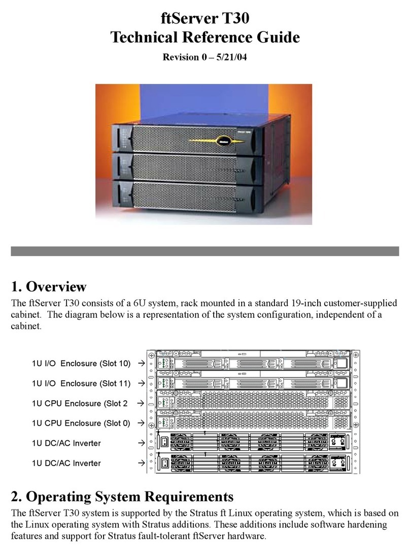
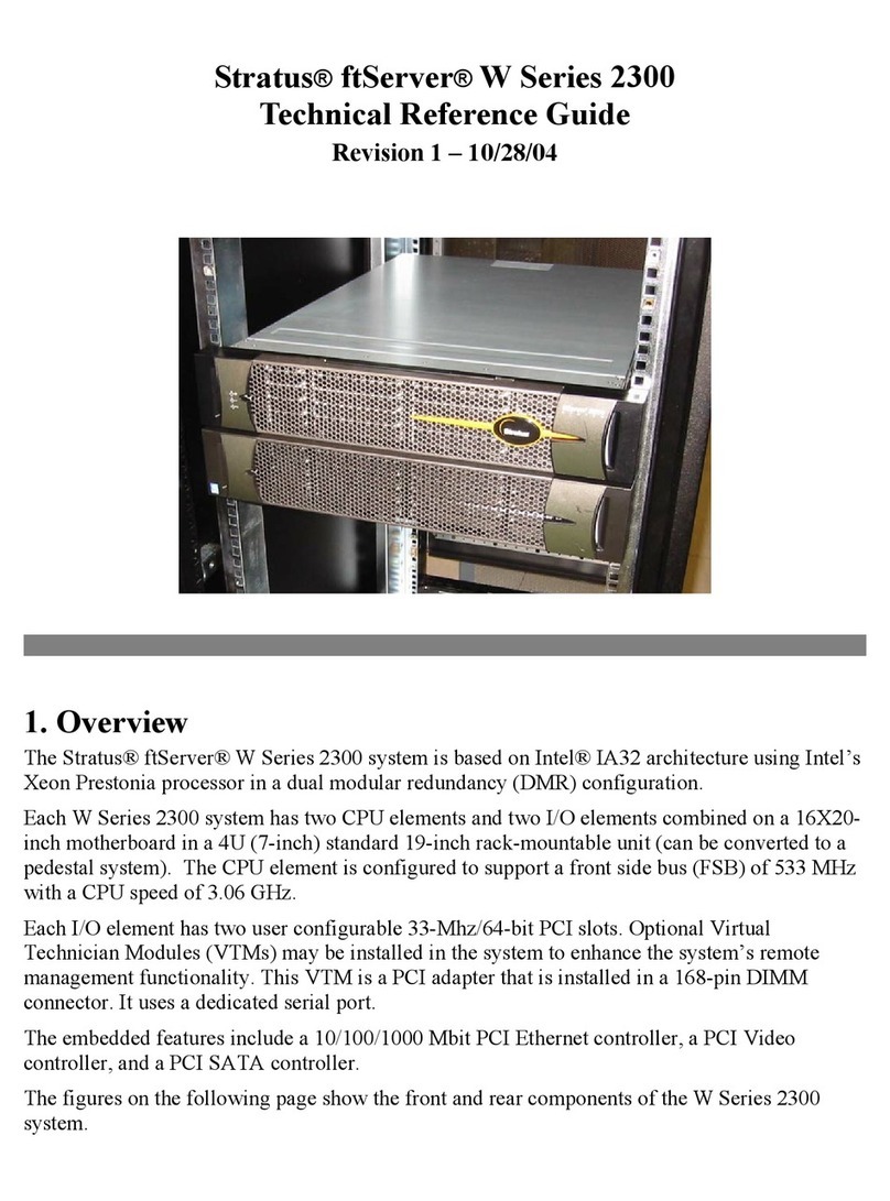
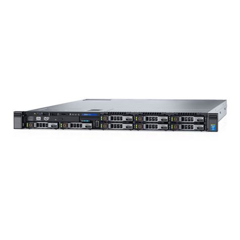
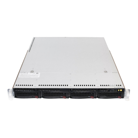
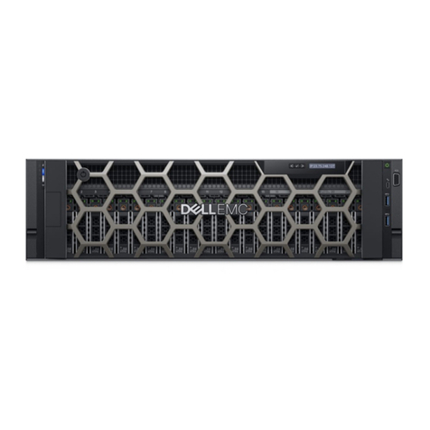
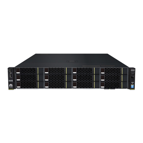
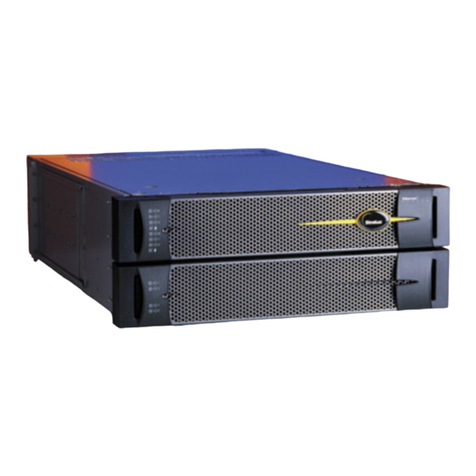
Stratus ftServer 2900 Series Technical manual

Stratus Technologies
R786-03
Stratus ftServer 29x0, 49x0, and 69x0 Systems: Site
Planning and Installation Guide

Notice
The information contained in this document is subject to change without notice.
UNLESS EXPRESSLY SET FORTH IN A WRITTEN AGREEMENT SIGNED BY AN AUTHORIZED
REPRESENTATIVE OF STRATUS TECHNOLOGIES, STRATUS MAKES NO WARRANTY OR REPRESENTATION
OF ANY KIND WITH RESPECT TO THE INFORMATION CONTAINED HEREIN, INCLUDING WARRANTY OF
MERCHANTABILITY AND FITNESS FOR A PURPOSE. Stratus Technologies assumes no responsibility or obligation
of any kind for any errors contained herein or in connection with the furnishing, performance, or use of this document.
Software described in Stratus documents (a) is the property of Stratus Technologies Bermuda, Ltd. or the third party,
(b) is furnished only under license, and (c) may be copied or used only as expressly permitted under the terms of the
license.
Stratus documentation describes all supported features of the user interfaces and the application programming
interfaces (API) developed by Stratus. Any undocumented features of these interfaces are intended solely for use by
Stratus personnel and are subject to change without warning.
This document is protected by copyright. All rights are reserved. Stratus Technologies grants you limited permission to
download and print a reasonable number of copies of this document (or any portions thereof), without change, for your
internal use only, provided you retain all copyright notices and other restrictive legends and/or notices appearing in the
copied document.
Stratus, the Stratus logo, ftServer, and the ftServer logo are registered trademarks of Stratus Technologies Bermuda,
Ltd. The Stratus Technologies logo, the Stratus 24 x 7 logo, ActiveService, ftScalable, Automated Uptime, and Active
Upgrade are trademarks of Stratus Technologies Bermuda, Ltd.
VMware, vSphere, ESX, ESXi, vCenter Server, and vMotion are registered trademarks or trademarks of VMware, Inc.
in the United States and/or other jurisdictions.
The registered trademark Linux is used pursuant to a sublicense from the Linux Mark Institute, the exclusive licensee
of Linus Torvalds, owner of the mark on a world-wide basis. FLEXlm is a registered trademark of Macrovision
Corporation.
All other trademarks are the property of their respective owners.
Manual Name: Stratus ftServer 29x0, 49x0, and 69x0 Systems: Site Planning and Installation Guide
Part Number: R786
Revision Number: 03
Software Release Number: Automated Uptime Layer for Windows-based ftServer Systems, Release 12.0.0.0
Automated Uptime Layer for Linux-based ftServer Systems, Release 11.1.6.0
Automated Uptime Layer for VMware vSphere-based ftServer Systems, Release 6.7.3.1
Publication Date: September 2019
Stratus Technologies, Inc.
5 Mill and Main Place, Suite 500
Maynard, Massachusetts 01754-2660
© 2019 Stratus Technologies Bermuda, Ltd. All rights reserved.

Contents iii
Contents
Preface xi
1. Site Planning for ftServer 2900, 4900, and 6900 Systems 1-1
Site Planning Overview 1-1
The Stratus ActiveService Network 1-3
Site Planning Checklist 1-3
System Documentation 1-7
2. Electrical Power Planning 2-1
Redundant Power Sources 2-1
AC Power and HVAC Service Requirements 2-2
AC Power Outlet Requirements 2-4
Connecting a System Directly to Separate AC Sources 2-5
Selecting a UPS Unit for ftServer Systems 2-6
Communicating with a UPS over a Network 2-6
Connecting a System Directly to a UPS 2-7
Power Cord Summary 2-7
Power Cords for ftServer Systems and Peripheral
Components 2-7
PDU Power Cords 2-9
Grounding Requirements 2-10
3. Space Planning 3-1
Room Requirements 3-1
Planning for Cables 3-3
4. Communications Line Planning 4-1
Supported Host Bus Adapters 4-2
Supported Storage Systems 4-2

Contents
iv Stratus ftServer 29x0, 49x0, and 69x0 Systems: Site Planning and Installation Guide (R786)
Connections from Storage Systems to ftServer Systems 4-3
Fibre Channel Connections 4-3
iSCSI Connections 4-4
Ethernet Cables 4-5
Category-6/Category-6A Cables 4-8
Telephone Line Connections 4-9
5. Rack Configuration Planning 5-1
Using PDUs 5-1
Determining PDU Requirements 5-2
Example of PDU Usage Calculation 5-4
6. Cabinet and Monitor Requirements 6-1
Cabinet Requirements 6-1
Monitor Requirements 6-5
7. Site Planning for Peripheral Components 7-1
ftScalable Storage System Requirements 7-1
Keyboard Requirements 7-2
Peripheral Components for Windows-based Systems 7-3
Peripheral Components for Linux-based Systems 7-4
Peripheral Components for VMware vSphere-based Systems 7-5
8. Before You Install the System 8-1
Safety Considerations 8-1
Safety Notices 8-1
Consignes de sécurité 8-4
9. Installing the System in a Cabinet 9-1
Required Tools 9-3
Numbering the Vertical Rails 9-3
Installing PDUs (Optional) 9-6
Installing a System Chassis 9-11
Installing the System Enclosures 9-21
Next Steps 9-24

Contents
Contents v
10. Connecting the System Components and Peripherals 10-1
PCI Adapters 10-1
System Ports and Backplane 10-3
Managing Cables 10-4
Connecting a Monitor, Mouse, and Keyboard 10-4
Connecting the ftServer System to External Storage Systems 10-4
Connecting ftServer Systems to the Network for
iSCSI Access 10-5
Connecting the VTM Ports to a Network 10-7
Connecting the External Modem 10-7
Connecting Tape Drives (Windows- and Linux-based Systems) 10-9
Next Steps 10-10
11. Connecting the System to Electrical Power 11-1
System Power Overview 11-1
Connecting the System to AC Power (Mains) 11-2
Connecting the System Directly to a UPS 11-3
Connecting Systems to Power Through PDUs 11-6
Next Steps 11-8
Appendix A. System Specifications A-1
System Specifications A-1
PCIe Adapter Specifications A-6
AAP87600 PDU Specifications A-7
Appendix B. Electrical Circuit and Wiring Information B-1
Fault Protection Requirements B-1
Grounding Considerations B-1
Circuit Wiring Diagrams B-2
Electrical Power Connectors B-9
PDU Safety Considerations B-10
Appendix C. Hardware Replacement and System Support C-1
Index Index-1

Figures
vi Stratus ftServer 29x0, 49x0, and 69x0 Systems: Site Planning and Installation Guide (R786)
Figures
Figure 6-1. Rail Clearance 6-4
Figure 9-1. System Components 9-2
Figure 9-2. EIA Vertical Rail Hole Pattern 9-4
Figure 9-3. Numbering the Middle Hole of 6U 9-5
Figure 9-4. PDU Components 9-7
Figure 9-5. Cage Nut Locations: PDU 9-8
Figure 9-6. Inserting Cage Nuts 9-9
Figure 9-7. Installing the Lower PDU (at U Number 1) 9-10
Figure 9-8. Installing the Upper PDU (at U Number 2) 9-11
Figure 9-9. Screw Locations on the Rear Vertical Rails 9-12
Figure 9-10. Attaching the Mounting Brackets and Inserting Guide
Screws (Rear View) 9-13
Figure 9-11. Removing the Front Panel from the Shelf Unit 9-14
Figure 9-12. Removing the System Backplane 9-15
Figure 9-13. Cage Nut Locations on Front Vertical Rails 9-16
Figure 9-14. Mounting the Shelf Unit on the Mounting Brackets 9-17
Figure 9-15. Securing the Shelf Unit to the Front Rails 9-18
Figure 9-16. Securing the Shelf Unit to the Mounting Brackets 9-19
Figure 9-17. Replacing the Front Panel in the Shelf Unit 9-20
Figure 9-18. Installing the CPU-I/O Enclosures in a Cabinet 9-22
Figure 9-19. Installing the Bezel 9-24
Figure 10-1. System Ports 10-3
Figure 10-2. Connecting Cables to the Modem 10-8
Figure 10-3. Mini-SAS (SFF-8088) Connector 10-9
Figure 10-4. Connecting a Tape Drive to an ftServer System 10-10
Figure 11-1. Connecting a System Directly to AC Power 11-3
Figure 11-2. Connecting a System to a UPS 11-5
Figure 11-3. Connecting the Systems Directly to PDUs 11-7
Figure A-1. ftServer 2900, 4900, or 6900 System:
CPU-I/O Enclosures: Front View A-2
Figure A-2. AAP87600PDU A-8
Figure B-1. Star Ground Example B-2
Figure B-2. PDU Power Input Labeling B-3
Figure B-3. ftServer Enclosure Power Input Labeling B-3
Figure B-4. Single-Phase 120V AC Circuit Connection B-4
Figure B-5. Single-Phase 240V AC Circuit Connection B-5
Figure B-6. Split-Phase 120/240 Volts AC Circuit Connection B-6

Tables
viii Stratus ftServer 29x0, 49x0, and 69x0 Systems: Site Planning and Installation Guide (R786)
Tables
Table 1-1. Ethernet PCIe Adapters 1-4
Table 1-2. ftServer 2900, 4900, and 6900 System Documentation 1-7
Table 1-3. Additional System Documentation for Windows-based
Systems 1-8
Table 1-4. Additional System Documentation for Linux-based
Systems 1-9
Table 1-5. Additional System Documentation for VMware
vSphere-based Systems 1-9
Table 2-1. Worksheet: Determining A-Side Power Requirements 2-3
Table 2-2. Worksheet: Determining B-Side Power Requirements 2-3
Table 2-3. Worksheet: Determining External Power Requirements 2-3
Table 2-4. HVAC Requirements 2-4
Table 2-5. Worksheet: A-Side External Power Outlet Requirements:
PDUs Used 2-4
Table 2-6. Worksheet: B-Side External Power Outlet Requirements:
PDUs Used 2-4
Table 2-7. Worksheet: A-Side External Power Outlet Requirements:
No PDUs 2-5
Table 2-8. Worksheet: B-Side External Power Outlet Requirements:
No PDUs 2-5
Table 2-9. Power Cords - ftServer Systems and Peripheral
Components to AC Power 2-7
Table 2-10. Power Cords Between ftServer Systems or Storage
Systems and a UPS 2-8
Table 2-11. Power Cords to Connect PDUs Directly to AC Power Mains 2-9
Table 2-12. Power Cords to Connect PDUs to a UPS 2-9
Table 2-13. System Power (Jumper) Cables to Connect ftServer
Systems to PDUs 2-10
Table 4-1. HBAs Supported by ftServer 2900, 4900, and 6900
Systems 4-2
Table 4-2. Storage Systems Supported by ftServer 2900, 4900,
and 6900 Systems 4-2
Table 4-3. Optical FC Cables 4-3
Table 4-4. Customer-Supplied Ethernet Cables 4-6
Table 5-1. Current and Rack-Space Requirements 5-3
Table 5-2. Calculating A-Side PDU and Rack-Space Requirements 5-4
Table 5-3. Example: Current and Rack-Space Requirements
(208 volts) 5-4

Tables
Tables ix
Table 5-4. Example: Calculating A-Side PDU and Rack-Space
Requirements 5-5
Table 7-1. Site Planning for ftScalable Storage G3 Systems 7-1
Table 7-2. V115 Keyboard: Specifications 7-2
Table 7-3. PCI Adapters and Peripheral Components:
Windows-based Systems 7-3
Table 7-4. PCI Adapters and Peripheral Components:
Linux-based Systems 7-4
Table 7-5. PCI Adapters and Peripheral Components:
VMware vSphere-based Systems 7-5
Table A-1. Cabinet Dimensions A-3
Table A-2. ftServer 2900, 4900, 6900 System Unit Specifications A-4
Table A-3. PCIe Adapter Specifications A-6
Table A-4. AAP87600 PDU: Specifications A-9
Table B-1. Connectors for AC Power Outlets B-9

Tables
xStratus ftServer 29x0, 49x0, and 69x0 Systems: Site Planning and Installation Guide (R786)

Preface xi
Preface
The Stratus ftServer 29x0, 49x0, and 69x0 Systems: Site Planning and Installation
Guide (R786) documents the site requirements and customer responsibilities related
to preparing a site for the installation of ftServer 2900, 4900, and 6900 systems. This
manual also documents how to install the system and its peripheral components.
This document is intended for personnel who are responsible for preparing a site for
the installation of an ftServer 2900, 4900, or 6900 system. It is also intended for system
administrators who are responsible for installing the system.
Revision Information
This document is a revision. This revision adds support for ftScalable Storage G4
systems connected to ftServer 2900, 4900, or 6900 systems running Automated
Uptime Layer for VMware vSphere-based ftServer Systems, Release 6.7.3.1 or higher.
Manual Organization
This manual is organized as follows:
Chapters 1 through 7 provide site-planning information:
–Chapter 1 provides an overviewofhow to preparea siteforan ftServersystem.
–Chapter 2 describes how to plan appropriate AC electrical power for an
ftServer system and its peripheral components.
–Chapter 3 describes how to plan sufficient space for an ftServer system.
–Chapter 4 describes how to plan the locations of an ftServer system and its
external components so that all communications and data cables will reach
their connection points.
–Chapter 5 describes how to plan a rack configuration for an ftServer system.
–Chapter 6 describes cabinet and monitor requirements.
–Chapter 7 describes how to prepare a site for an ftServer system’s peripheral
components.

Preface
xii Stratus ftServer 29x0, 49x0, and 69x0 Systems: Site Planning and Installation Guide (R786)
Chapters 8 through 11 provide hardware-installation information:
–Chapter 8 describes safety-related steps to take before you begin to install an
ftServer system.
–Chapter 9 describes how to install an ftServer system in a cabinet.
–Chapter 10 describes how to connect ftServer system components and
peripheral components.
–Chapter 11 describes how to connect an ftServer system to electrical power.
Appendix A provides system specifications.
Appendix B provides electrical circuit and wiring information.
Appendix C provides information about hardware replacement and system
support.
ftScalable Storage G4 System Documentation
For detailed information about ftScalable Storage G4 systems, see the following
manual and web site:
Using ftScalable Storage G4 Systems (R789)
https://www.seagate.com/support/raid-systems/
Notation Conventions
This document uses the notation conventions described in this section.
Warnings, Cautions, Notices, and Notes
Warnings, cautions, notices, and notes provide special information and have the
following meanings:
WARNING
!
A warning indicates a hazardous situation that, if not
avoided, could result in death or serious injury.
AVERTISSEMENT
!
Unavertissementindiqueunesituationdangereusequi,si
pas évitée, pourrait entraîner la mort ou des blessures
graves.

Preface
Preface xiii
CAUTION
!
A caution indicates a hazardous situation that, if not
avoided, could result in minor or moderate injury.
MISE EN GARDE
!
Une mise en garde indique une situation dangereuse qui,
si pas évitée, pourrait entraîner des blessures mineures
ou modérées.
NOTICE
A notice indicates information that, if not acted on, could
result in damage to a system, hardware device, program,
or data, but does not present a health or safety hazard.
NOTE
A note provides important information about the operation
of an ftServer system or related equipment or software.
Typographical Conventions
The following typographical conventions are used in this document:
The bold font emphasizes words in text or indicates text that you type, the name of
a screen object, or the name of a programming element. For example:
Before handling or replacing system components, make sure that you are
properly grounded by using a grounded wrist strap.
In the System Properties dialog box, click the Hardware tab.
Call the RegisterDeviceNotification function.
The italic font introduces new terms and indicates programming and command-line
arguments that the user supplies. For example:
Many hardware components are customer-replaceable units (CRUs), which
can be replaced on-site by system administrators with minimal training or tools.
copy filename1 filename2
Pass a pointer for the NotificationFilter parameter

Preface
xiv Stratus ftServer 29x0, 49x0, and 69x0 Systems: Site Planning and Installation Guide (R786)
The monospace font indicates sample program code and output, including
message text. For example:
#include <iostream.h>
The operation completed successfully.
The monospace font also represents text that would appear on your display screen
when working in a text-based console on a Linux- or VMware vSphere-based
system. The monospace bold font represents text you must type in examples that
contain both user input and system output. The monospace italic font represents
terms in command lines that are to be replaced by literal values. For example:
To display the state of a CPU enclosure, type a command in the following
format:
/opt/ft/bin/ftsmaint ls n
If you type /opt/ft/bin/ftsmaint ls 0 at the prompt, the following
output appears:
H/W Path : 0
Description : Combined CPU/IO
.
.
.
The percent sign (%), dollar sign ($), and number sign (#) are default prompt signs
that have a specific meaning at the command prompt of a Linux- or VMware
vSphere-based system. Although a prompt is sometimes shown at the beginning
of a command line as it would appear on the screen, you do not type it.
– % or $ indicates you are logged in to a standard user account and are subject
to certain access limitations. The prompt displayed on the screen depends on
your shell environment, for example, csh (%) or bash ($).
–#indicates you are logged in to the system administrator account and have
superuser access. Users of this account are referred to as root. The #prompt
sign used in an example indicates the command can be issued only by root.

Preface
Preface xv
Getting Help
If you have a technical question about ftServer system hardware or software, try these
online resources first:
Online documentation at the StrataDOC web site. Stratus provides
complimentary access to StrataDOC, an online-documentation service that
enables you to view, search, download, and print customer documentation. You
can access StrataDOC at the following web site:
http://stratadoc.stratus.com
Online support from Stratus Customer Service.You can findthe latest technical
information about an ftServer system in the Stratus Customer Service Portal at the
following web site:
http://www.stratus.com/go/support
The Service Portal provides access to Knowledge Base articles for all Stratus
product lines. You can locate articles by performing a simple or advanced keyword
search, viewing recent articles or top FAQs, or browsing a product and category.
To log in to the Service Portal, enter your employee user name and password or, if
you have not been provided with a login account, click Register Account. When
registering a new account, ensure that you specify an email address from a
company that has a service agreement with Stratus.
Online product support for Microsoft®products. Your primary source for
support is the computer manufacturer who provided your software, or an
authorized Microsoft Support Provider. You can also find the latest technical
information about Microsoft Windows®and other Microsoft products through online
product support at the Microsoft Help and Support web site:
http://support.microsoft.com/
Online product support for Red Hat® Linux®products. Your primary source for
support is the manufacturer who provided your software, or Red Hat Global
Support Services. You can also find the latest technical information about Red Hat
Enterprise and Standard Linux through online product support at the Red Hat
Support Web site:
http://www.redhat.com/apps/support/
Online product support for VMware vSphere®products. You can find the latest
technical information about VMware vSphere through online product support at the
VMware Support web site:
http://www.vmware.com/support/

Preface
xvi Stratus ftServer 29x0, 49x0, and 69x0 Systems: Site Planning and Installation Guide (R786)
If you cannot resolve your questions with these online self-help resources, and the
ftServer system is covered by a service agreement, contact the Stratus Customer
Assistance Center (CAC) or your authorized Stratus service representative.To contact
the CAC, use the Service Portal to log a support request. Click Customer Support and
Add Issue, and then complete the Create Issue form. A member of our Customer
Service team will be glad to assist you.
Commenting on This Manual
You can comment on this manual using one of the following methods. When you
submit a comment, be sure to provide the manual’s name and part number, a
description of the problem, and the location in the manual where the affected text
appears.
From StrataDOC, click the site feedback link at the bottom of any page. In the
pop-up window, answer the questions and click Submit.
From any email client, send email to [email protected].
From the Stratus Customer Service Portal, log on to your account and create a new
issue.
Stratus welcomes any corrections and suggestions for improving this manual.
Regulatory Notice
All regulatory notices are provided in Compliance Information for Stratus
Products (R002G), which is available on StrataDOC:
https://stratadoc.stratus.com/compliance_info/Compliance_Information_for_Strat
us_Products.htm

Site Planning for ftServer 2900, 4900, and 6900 Systems 1-1
Chapter 1
Site Planning for ftServer 2900, 4900,
and 6900 Systems1-
For an overview of required information and tasks you need to perform to prepare a site
for ftServer 2900, 4900, and 6900 systems, see:
“Site Planning Overview” on page 1-1
“Site Planning Checklist” on page 1-3
“System Documentation” on page 1-7
NOTICES
1. See “Safety Notices” on page 8-1 for a list of
important safety notices that you should review as
part of your site planning.
2. See “Regulatory Notice” for information about
standards compliance.
Site Planning Overview
Site planning for fault-tolerant systems includes:
Purchasing an appropriate cabinet and monitor
Provide a monitor that meets the system’s requirements.
NOTE
A monitor, keyboard, and mouse are required to install
Automated Uptime Layer.
If you do not purchase a cabinet from Stratus, provide a cabinet that meets the
system’s requirements.

Site Planning Overview
1-2 Stratus ftServer 29x0, 49x0, and 69x0 Systems: Site Planning and Installation Guide (R786)
Electrical power planning
Provide electrical power sources that meet the requirements of the system and
optional components, optionally including the purchase of a qualified
uninterruptible power supply (UPS).
Space planning
Provide adequate space for the system or cabinet and for a desk or table to
accommodate components outside a cabinet. Also provide enough space for
servicing the systems and components.
Provide an environment that meets the system’s requirements for ambient
temperature and air quality.
Communications line planning
Provide sufficient network and analog telephone lines and plan the location of the
system and external components to accommodate the lengths of the connecting
cables.
Rack space planning
Ensure that the power distribution units (PDUs) supply sufficient power to the
components you have purchased and that you have sufficient space available in
an appropriate cabinet.
Planning for peripheral components
Provide for the electrical, cooling, power, and space needs of any peripheral
components.
For information about obtaining documents related to your ftServer system, see
“System Documentation” on page 1-7.
During the site planning and preparation processes, work closely with your facilities
grouporcontractor to determinespace,power,and environmental requirements. Enlist
their help to provide a suitable location with sufficient alternating current (AC) power,
heating, ventilation and air conditioning (HVAC) capabilities, and network and
telephone connections.
If your system is covered by a service agreement and you need help with site planning,
contact the Stratus Customer Assistance Center (CAC) or your authorized Stratus
service representative. If you have a contract with the CAC or your authorized Stratus
service representative to install the system, contact them after you have prepared the
installation site and moved the system to the site. For more information about the CAC,
see “Getting Help” in the Preface or the http://www.stratus.com/go/support web site.

Site Planning Checklist
Site Planning for ftServer 2900, 4900, and 6900 Systems 1-3
See Appendix A for the specifications of the base ftServer systems and of PDUs. See
Chapter 7 for specifications of other components.
The Stratus ActiveService Network
The Stratus ActiveService Network (ASN) is a network that allows your ftServer system
to automatically report problems to the Stratus Customer Assistance Center (CAC) or
your authorized Stratus service representative, and that can allow the CAC or your
authorized Stratus service representative to remotely diagnose, troubleshoot, and
resolve problems online.
To enable connectivity to the ASN, you connect a pair of partnered Ethernet ports, one
from each CPU-I/O enclosure in your system, to a network that has Internet access.
For additional protection, if you connect the Ethernet port of the VTM in each enclosure
to a network with Internet access, the VTMs can communicate with the ASN even when
the host operating system is not running or is unresponsive.
If Internet access is not available, or if you wish to have a backup method of connecting
to the ASN, you can also connect the optional ASN modem to your system, which
allows either thehost operatingsystemora VTM to communicatewith the ASNthrough
a telephone dialup connection.
Site Planning Checklist
Referring to the information in this document, answer the following questions:
Planning for ASN Connectivity
❏Will your system connect to the ASN? If so, will it connect over an ASN modem or
the Internet?
❏If your system will use the Internet to connect to the ASN, do you have an Internet
connection available?
❏If your system will use an ASN modem, do you have an external analog telephone
line available for the ASN modem?
NOTE
A dedicated phone line provides the most reliable service.
ASN calls routed through a PBX may be slow due to load
on the PBX, or may not complete successfully due to
disconnections. If you must use a PBX, do not route the
telephone extension through a switchboard; instead,
provide a direct-dial analog number.
❏Do you have an additional telephone connection and telephone near the operator’s
station for voice communications when calling for support?

Site Planning Checklist
1-4 Stratus ftServer 29x0, 49x0, and 69x0 Systems: Site Planning and Installation Guide (R786)
Planning for Network Connectivity
❏All ftServer 2900, 4900, and 6900 systems contain four embedded 1-gigabit
Ethernet (GbE) ports that operate at 10 or 100 Megabits-per-second (Mbps) or at
1 gigabit-per-second (Gbps). In addition, four embedded 10GbE ports that operate
at 100 Mbps or at 1 or 10 Gbps are standard on ftServer 4900 and ftServer 6900
systems. Also, you can add optional Ethernet PCI adapters to provide additional
Ethernet bandwidth.
In Table 1-1, indicate the number of Ethernet ports you will use, and plan network
connections accordingly.
Planning for External Storage Options
❏Will your system connect to external Fibre Channel storage enclosures? If so, the
system requires a pair of Fibre Channel HBAs, which are provided when you order
the storage enclosure. If you order the enclosure at the same time you order the
system, the required Fibre Channel HBAs are installed at the factory. See
Chapter 7 for descriptions of the storage enclosures provided by Stratus and the
names of the PCI adapters required for supported storage enclosures.
Table 1-1. Ethernet PCIe Adapters
Adapter Number of Ports
Embedded Dual-Port 1 Gigabit Ethernet (1GbE) PCI-Express
Adapters (2) 4
Embedded Dual-Port 10 Gigabit Ethernet (10GbE)
PCI-Express Adapters (2)†
† Standard on ftServer 4900 and ftServer 6900 systems, but not availableon ftServer 2900
systems. See “Category-6/Category-6A Cables” on page 4-8 for additional site-planning
requirements for embedded 10GbE ports.
U113 Dual-Port 10/100/1000 Base-T Ethernet PCI-Express
Adapter
U117A Dual-Port Fiber 10-Gbps Ethernet PCI-Express
Adapter ‡(Windows- and VMware vSphere-based systems)
‡ Available only on ftServer 4900 and 6900 systems.
U584 Dual-Port Fiber 10-Gigabit Ethernet PCI-Express
Adapter (Linux-based ftServer 4900 with riser and 6900
systems)
U118 Dual-Port RJ-45 10-Gigabit Ethernet PCI-Express
Adapter
Total Number of Ports
This manual suits for next models
2
Table of contents
Other Stratus Server manuals

Stratus
Stratus ftServer 2500 Technical manual

Stratus
Stratus ftServer 3000 Series Technical manual

Stratus
Stratus ftServer W 2300Series Use and care manual

Stratus
Stratus ftServer 2600 Instruction Manual

Stratus
Stratus ftserver 3300 Technical manual

Stratus
Stratus ftServer T30 Use and care manual

Stratus
Stratus ftServer 2510 Technical manual

Stratus
Stratus AA-E99100 Instruction Manual
Stratus
Stratus ftServer V 2404 Manual

Stratus
Stratus ftServer V 2302 Technical manual