Stratus ftServer 3000 Series Technical manual

Stratus Technologies
R472-03
Stratus ftServer 3000 Series:
Site Planning Guide
r472.book Page 1 Friday, June 21, 2002 11:46 AM

Notice
The information contained in this document is subject to change without notice.
UNLESS EXPRESSLY SET FORTH IN A WRITTEN AGREEMENT SIGNED BY AN AUTHORIZED
REPRESENTATIVE OF STRATUS TECHNOLOGIES, STRATUS MAKES NO WARRANTY OR REPRESENTATION
OF ANY KIND WITH RESPECT TO THE INFORMATION CONTAINED HEREIN, INCLUDING WARRANTY OF
MERCHANTABILITY AND FITNESS FOR A PURPOSE. Stratus Technologies assumes no responsibility or obligation
of any kind for any errors contained herein or in connection with the furnishing, performance, or use of this document.
Software described in Stratus documents (a) is the property of Stratus Technologies Bermuda, Ltd. or the third party,
(b) is furnished only under license, and (c) may be copied or used only as expressly permitted under the terms of the
license.
Stratus documentation describes all supported features of the user interfaces and the application programming
interfaces (API) developed by Stratus. Any undocumented features of these interfaces are intended solely for use by
Stratus personnel and are subject to change without warning.
This document is protected by copyright. All rights are reserved. No part of this document may be copied, reproduced,
or translated, either mechanically or electronically, without the prior written consent of Stratus Technologies.
Stratus, the Stratus logo, Continuum, Continuous Processing, StrataLINK, and StrataNET are registered trademarks
of Stratus Technologies Bermuda, Ltd.
The Stratus Technologies logo, ftServer, ftServer with design, Stratus 24 x 7 with design, The World’s Most Reliable
Servers, The World’s Most Reliable Server Technologies, ftGateway, ftMemory, ftMessaging, ftStorage, Selectable
Availability, XA/R, SQL/2000, and The Availability Company are trademarks of Stratus Technologies Bermuda, Ltd.
VERITAS, VERITAS SOFTWARE, the VERITAS logo, Business Without Interruption, VERITAS The Data Availability
Company, and VERITAS Volume Manager are trademarks or registered trademarks of VERITAS Software Corporation
in the U.S. and/or other countries.
All other trademarks are the property of their respective owners.
Manual Name: Stratus ftServer 3000 Series: Site Planning Guide
Part Number: R472
Revision Number: 03
ftServer System Software Release Number: 1.3.0
Printing Date: July 2002
Stratus Technologies, Inc.
111 Powdermill Road
Maynard, Massachusetts 01754-3409
© 2002 Stratus Technologies Bermuda, Ltd. All rights reserved.
r472.book Page 2 Friday, June 21, 2002 11:46 AM

Contents iii
Contents
Preface vii
1. Site Planning Overview 1-1
ftServer 3000-Series Systems 1-1
Using the Site Planning Checklist 1-2
Site Planning Checklist 1-3
2. System Overview for Site Planning 2-1
Pedestal System 2-3
Rack-Mountable System 2-5
Monitor Options 2-7
V122 17-Inch Color Monitor 2-8
V125 Monitor Unit 2-8
Using Your Own Monitor, Keyboard, and Mouse 2-9
Ultra160 SCSI Storage Enclosure 2-10
ftStorage Fibre Channel Array 2-11
Tape Drives 2-13
Internal T811 Tape Drives 2-13
External Tape Drives 2-13
Uninterruptible Power Supply (UPS) 2-15
3. Site Requirements 3-1
Space and HVAC Requirements 3-1
Bringing a System Out of Storage 3-2
Specifications and HVAC Requirements 3-2
Electrical Power Requirements 3-5
Calculating Power Requirements 3-6
Power Cord Lengths and Plug Types 3-7
System, Monitor, and Tape Drive Power Cords 3-7
ftStorage Fibre Channel Array and Ultra160 SCSI Storage
Enclosure Power Cords 3-8
r472.book Page iii Friday, June 21, 2002 11:46 AM

Contents
iv Stratus ftServer 3000 Series: Site Planning Guide (R472)
External Modem Power Cords 3-8
UPS Power Cords 3-10
Network and Telephone Line Connection Requirements 3-11
ftGateway Phone Line Requirements 3-12
Interface Cabling Requirements 3-12
Interface Cables You Supply 3-13
Interface Cables Stratus Supplies 3-14
4. Planning Power Connections 4-1
Connecting Power to a System without a UPS 4-1
Connecting a System to Power with a UPS 4-2
APC Smart-UPS 1400 4-3
APC Smart-UPS 3000 4-4
Appendix A. Electrical Circuit and Wiring Information A-1
Fault Protection Requirements A-1
Grounding Considerations A-1
Circuit Wiring Diagrams A-2
Electrical Power Connectors A-9
Appendix B. Standards Compliance B-1
Index Index-1
r472.book Page iv Friday, June 21, 2002 11:46 AM

Figures v
Figures
Figure 2-1. Typical System Installation 2-2
Figure 2-2. Pedestal System Configuration 2-4
Figure 2-3. Rack-Mounted System Configuration 2-6
Figure 2-4. I/O Panel 2-7
Figure 2-5. V125 Monitor Unit 2-8
Figure 2-6. Ultra160 SCSI Storage Enclosure 2-10
Figure 2-7. Front and Rear Views of the D570 Array 2-11
Figure 2-8. Front and Rear Views of the D580 Array 2-12
Figure 2-9. T511 Tape Drive and T512 Autoloader 2-14
Figure 2-10. T513 Tape Drive 2-15
Figure 4-1. Power Connections for an ftServer System 4-2
Figure A-1. Star Ground Example A-2
Figure A-2. Power Input Labeling A-3
Figure A-3. Single-Phase 110-VAC Circuit Connection A-4
Figure A-4. Single-Phase 220-VAC Circuit Connection A-5
Figure A-5. Three-Phase 208-VAC, Y-, or -Source Circuit Connection,
Phase-to-Neutral A-6
Figure A-6. Three-Phase 208-VAC, Y-, or -Source Circuit Connection,
Phase-to-Phase A-7
Figure A-7. Three-Phase 380-VAC, Y-, or -Source Circuit Connection,
Phase-to-Neutral A-8
r472.book Page v Friday, June 21, 2002 11:46 AM

vi Stratus ftServer 3000 Series: Site Planning Guide (R472)
Tables
Table 3-1. AC Power Service Requirements 3-5
Table 3-2. Worksheet for Calculating Power Service Requirements 3-6
Table 3-3. System, Monitor, and Tape Drive Power Cords 3-7
Table 3-4. ftStorage and Ultra160 Enclosure Power Supply Power
Cords 3-8
Table 3-5. External Modem Power Cords 3-8
Table 3-6. UPS Power Cords 3-10
Table 3-7. Customer-Supplied Interface Cables 3-13
Table 3-8. Interface Cables Available from Stratus 3-14
Table 4-1. Smart-UPS 1400 Models for Pedestal Systems 4-3
Table 4-2. Smart-UPS 1400 Models for Rack-Mounted Systems 4-3
Table 4-3. Smart-UPS 3000 Models for Pedestal Systems 4-4
Table 4-4. Smart-UPS 3000 Models for Rack-Mounted Systems 4-4
Table A-1. Connectors for AC Power Outlets A-9
Table B-1. EMI Standards B-1
Table B-2. Immunity Standards B-2
Table B-3. Safety Standards B-2
Table B-4. Noise Standards B-2
r472.book Page vi Friday, June 21, 2002 11:46 AM

Preface vii
Preface
Purpose of This Manual
The Stratus ftServer 3000 Series: Site Planning Guide (R472) documents the
operating environment required to install systems in the ftServer 3000 series, including
space, power and HVAC requirements and the required cableswith an uninterruptible
power supply (UPS).
Audience
This manual is intended for those responsible for preparing a site for the installation of
a system in the ftServer 3000 series.
Revision Information
This manual is a revision. This revision incorporates site planning information for:
•Ultra160 SCSI storage enclosure and the U521 Two-Port Ultra160 SCSI PCI
Adapter
•ftGateway, which allows multiple ftServer systems to connect to the Stratus Service
Network (SSN) through one system that has a modem connection
r472.book Page vii Friday, June 21, 2002 11:46 AM

Preface
viii Stratus ftServer 3000 Series: Site Planning Guide (R472)
Notation Conventions
This document uses the notation conventions described in this section.
Warnings, Cautions, and Notes
Warnings, cautions, and notes provide special information and have the following
meanings:
WARNING
!
A warning indicates a situation where failure to take
or avoid a specified action could cause bodily harm
or loss of life.
CAUTION
!
A caution indicates a situation where failure to take or
avoid a specified action could damage a hardware device,
program, system, or data.
NOTE
A note provides important information about the operation
of an ftServer system.
Typographical Conventions
The following typographical conventions are used in this document:
•The bold font emphasizes words in text and also indicates text that you type or the
name of screen objects, such as menu names, command buttons, icon names,
tabs, check box names, and dialog box names. For example:
Before handling or replacing the clock card, make sure that you are properly
grounded by using a grounded wrist strap.
In the System Properties dialog box, click the Hardware tab.
•The italic font introduces new terms or indicates command-line arguments that the
user defines. For example:
Each ftServer system uses Dual Modular Redundancy.
copy filename1 filename2
r472.book Page viii Friday, June 21, 2002 11:46 AM

Preface
Preface ix
•The monospace font indicates sample program code and output, including
message text. For example:
#include <iostream.h>
The operation completed successfully.
Related Documentation
This section contains a complete list of manuals about ftServer software and hardware.
ftServer 3000-Series Software-Related Manuals
The software-related manuals describe how to install and use ftServer System
Software on systems in the ftServer 3000 series, and how to manage systems in the
ftServer 3000 series.
Software Manual Content
Stratus ftServer 3000 Series: System
Administrator’s Guide (R008W)
Describes how to administer and
troubleshoot systems in the ftServer 3000
series. Explains how to configure and use
ftServer Management Console.
Stratus ftServer Software Installation and
Configuration Guide (R002W)
Explains how to install and configure ftServer
Software.
Stratus ftServer Access User’s
Guide (R003W)
Explains how to configure and use ftServer
Access Console to remotely control, monitor,
and troubleshoot an ftServer system.
Stratus ftServer 3000 Series: Release
Notes (R010W)
Provides release-specific information about
systems in the ftServer 3000 series.
Stratus ftServer Software Availability
Manager User’s Guide (R007W)
Explains how to configure and use ftServer
Software Availability Manager.
Stratus ftServer: SSN Configuration
Guide (R013W)
Explains how to set up and configure the
system for support by the Stratus Service
Network (SSN).
r472.book Page ix Friday, June 21, 2002 11:46 AM

Preface
xStratus ftServer 3000 Series: Site Planning Guide (R472)
ftServer 3000-Series Hardware-Related Manuals
The hardware-related manuals document how to prepare a site for the installation of a
system in the ftServer 3000 series, and how to install, operate, and service ftServer
hardware.
ftServer Online Documentation
The ftServer Help and Manuals folder on the ftServer desktop contains links to the
Stratus ftServer manuals in Portable Document Format (PDF) and the same
documents in HTML Help format.
The Manuals folder provides the documentation in PDF; the Hardware Help folder is
a single HTML Help system that contains the information in the hardware-related
manuals; and Software Help is another HTML Help system that contains the
information in the software-related manuals.
To gain access to the documents on the World Wide Web, point your browser to the
ftServer StrataDOC Web site:
http://stratadoc4ftserver.stratus.com
Hardware Manual Content
Stratus ftServer 3000 Series: Site Planning
Guide (R472)
Explains how to prepare a site for a system.
Stratus ftServer 3000 Series: Hardware
Installation Instructions (R475)
Explains how to install pedestal systems.
Stratus ftServer 3000 Series: Operation and
Maintenance Guide (R473)
Explains how to operate, troubleshoot, and
service systems.
Stratus ftServer 3000 Series: CRU
Reference Guide (R474)
Lists the part numbers of
customer-replaceable units (CRUs).
Stratus ftServer: PCI Adapter Guide (R461) Describes the PCI adapters that Stratus
supports for ftServer systems.
Stratus ftServer 3000 Series:
Rack-Mounting and Installing a
System (R479)
Explains how to use the rack-mounting kit to
install a rack-mounted system and optional
components.
Stratus ftStorage Fibre Channel Array
Installation Guide (R503)
Describes how to install and configure the
ftStorage Fibre Channel Array hardware and
software.
r472.book Page x Friday, June 21, 2002 11:46 AM

Preface
Preface xi
Getting Help
If you have a technical question about Windows®2000 or an ftServer system, try these
online resources first:
•Online support from Stratus Customer Service. You can find the latest technical
information about an ftServer system through online product support at the Stratus
Customer Service Web site:
http://www.stratus.com/support/technics.htm
•Online product support for Microsoft®products. Your primary source for
support is the computer manufacturer who provided your software, or an
authorized Microsoft Support Provider. You can also find the latest technical
information about Microsoft products through online product support at the
Microsoft Web site:
http://www.microsoft.com/windows2000/support/
If you are unable to resolve your questions with the help available at these online sites,
and the ftServer system is covered by a service agreement, please contact the Stratus
Customer Assistance Center (CAC) or your authorized Stratus service representative.
For information about how to contact the CAC, see:
http://www.stratus.com/support/cac/
Your system administrator may have configured a Stratus Support phone number in
ftServer Management Console (ftSMC), a snap-in to Microsoft Management Console
(MMC). In ftSMC, under Stratus Configuration, click Service Network to display the
node’s properties. The properties include a Stratus Support Phone item. The value of
this property, if configured, is a telephone number you can call for support. For more
information about ftSMC, refer to the Stratus ftServer 3000 Series: System
Administrator’s Guide (R008W).
Hardware Replacement and System Support
Hardware replacement and system support services require a service agreement and
are handled through the CAC or an authorized Stratus service representative. Support
services are facilitated by the Stratus Service Network (SSN), a worldwide network with
secure dial-back capabilities.
If the system is covered by a service agreement, you can receive advanced parts
exchange and support services as outlined in your agreement. Support coverage can
include remote system support and monitoring, telephone support, electronic support
services, and hardware remedial services.
The Stratus service model enables you to replace customer-replaceable units (CRUs)
in accordance with the procedures explained in the documentation provided with your
system. All field-replaceable units (FRUs) require replacement by authorized service
r472.book Page xi Friday, June 21, 2002 11:46 AM

Preface
xii Stratus ftServer 3000 Series: Site Planning Guide (R472)
personnel. All distributor-replaceable units (DRUs) must be returned to your distributor
for repair or replacement. If you are unsure whether the part needing replacement is a
CRU, FRU, or DRU, contact the CAC or your authorized Stratus service representative,
or see the following Stratus Web page:
http://www.stratus.com/support/ftserver/3200parts
This Web page provides illustrations of the hardware components of systems in the
ftServer 3000 series.
If you suspect that a CRU has failed, and the system is not covered by a service
agreement but is still under warranty, contact the party from whom you purchased your
system for return instructions. You may also obtain return instructions from your local
Stratus sales offices; from the Stratus ftServer Service Warranty Parts Replacement
Process and Return Instructions Web page
http://www.stratus.com/support/ftserver/partreturn.htm; or from your local authorized
Stratus service representative. These sources can also provide you with information
about the customer service assistance options available to you.
Ordering Manuals
To order manuals, customers in North America can call the CAC at (800) 221-6588 or
(800) 828-8513, 24 hours a day, 7 days a week. Customers outside North America can
contact the nearest Stratus Sales office, CAC office, or distributor. Manual orders will
be forwarded to Order Administration.
Commenting on the Documentation
Stratus welcomes any corrections and suggestions for improving its documentation.
Send your feedback by email to Comments@stratus.com. If it is possible, please
include specific information about the documentation on which you are commenting:
•For a manual, include the book title and page numbers.
•For online Help, include the Help subject and topic title.
This information will assist Stratus Publications in making any needed changes to the
ftServer documentation. Your assistance is most appreciated.
r472.book Page xii Friday, June 21, 2002 11:46 AM

Site Planning Overview 1-1
Chapter 1
Site Planning Overview1-
Careful selection, planning, and preparation of the installation site for your ftServer
system are important activities that can contribute directly to the proper operation and
reliability of your system. Before installing your system, make sure that:
•You are familiar with the information in “ftServer 3000-Series Systems” below and
in Chapter 2
•Your installation site meets the requirements described in this site planning guide.
Use the checklist in “Using the Site Planning Checklist” on page 1-2 to track your
site preparation progress. The checklist provides a step-by-step breakdown of the
specific activities involved in site planning.
During the site planning and preparation processes, work closely with your facilities
group or contractor to determine space, power, and environmental requirements and
to provide a suitable location with sufficient AC power, HVAC capabilities, and
communications connections.
If your system is covered by a service agreement and you need help with site planning,
call the Stratus Customer Assistance Center (CAC) or your authorized Stratus service
representative. If you have contracted with the CAC or your authorized Stratus service
representative for installation of the system, contact them after you move the system
to the installation site. For more information about the CAC, see “Getting Help” in the
Preface.
ftServer 3000-Series Systems
Systems in the ftServer 3000 series are enterprise-class servers that support the
Windows 2000 Advanced Server operating system on a fault-tolerant hardware
platform. These servers operate with software customized by Stratus for
fault-tolerance, which provides fault-hardened device drivers, enhancements to the
operating system, and application reliability and availability.
Systems in the ftServer 3000 series incorporate Intel®Pentium®III processors and
one-way (one processor per CPU enclosure) or two-way (two processors per CPU
enclosure) symmetric multiprocessing (SMP). To achieve fault tolerance, the system
contains pairs of CPU enclosures, I/O enclosures, and power supplies. If one
component of a pair fails, the system switches operation over to the remaining
r472.book Page 1 Friday, June 21, 2002 11:46 AM

Using the Site Planning Checklist
1-2 Stratus ftServer 3000 Series: Site Planning Guide (R472)
component. The system also has a storage enclosure, which can house up to six
physical hard drives, which are mirrored, thus providing three logical drives.
The ftServer 3000 series contains the following models:
•ftServer 3210. Entry-level systems that connect to the Stratus Service Network
(SSN) over an external modem. This implementation uses Windows Routing and
Remote Access Service (RRAS), and Internet Authentication Service (IAS) to
implement the connection to the SSN. SSN connectivity is only possible if Windows
2000 is operational.
•ftServer 3220. Entry-level systems that contain an ftServer Access Adapter. This
adapter connects to the SSN over a PCMCIA modem and provides SSN
connectivity even when Windows 2000 is not operational. The adapter also allows
internal administrators to remotely service the system over an IP network,
regardless of the state of the operating system.
Systems that contain two duplexed ftServer Access Adapters provide the highest level
of availability. Each adapter contains a PCMCIA modem, which allows the CAC or your
authorized Stratus service representative to remotely manage the system over the
SSN. An Ethernet port allows you to connect the cards to your network so that you can
perform remote management from remote systems.
ftServer System Software has been tested and qualified with Windows 2000 Advanced
Server and a qualified service pack for the English, French, German, Spanish,
Japanese, Simplified Chinese, Traditional Chinese, and Korean languages.
Using the Site Planning Checklist
The Site Planning Checklist helps you to ensure that the installation site provides the
following:
•Proper location suitable for the reliable operation of computer equipment
•Adequate space for the system, its servicing, and its associated components,
cables, and furniture
•Environment that maintains proper air cleanliness, and required temperature and
humidity ranges
•Electrical power sources that meet the system’s requirements
•Provisions for network connectivity (as required) and communications over an
analog telephone line
See “Specifications and HVAC Requirements” on page 3-2 for detailed system
specifications and requirements.
r472.book Page 2 Friday, June 21, 2002 11:46 AM

Site Planning Checklist
Site Planning Overview 1-3
Use the Site Planning Checklist to help you plan and prepare the installation site. As
you perform each step, check the associated box. Before the system is installed,
review this checklist to ensure that all the necessary steps have been taken for an
efficient installation of the system.
Site Planning Checklist
Make sure you answer the following questions:
❏Does your system include any of the following optional PCI adapters? If so, indicate
how many of each.
❏Does your system include internal tape drives, an option for pedestal units only, or
external tape drives and U516 One-Port Ultra2 SCSI PCI Adapters?
❏Does your system include any ftStorage Fibre Channel array storage enclosures
and U514 Fibre Channel PCI Adapters?
❏Does your system include an Ultra160 SCSI storage enclosure and U521 Two-Port
Ultra160 SCSI PCI Adapter?
❏Will you provide power to the system through an uninterruptible power supply
(UPS)?
❏Will you supply your own monitor, keyboard, and mouse, or will you use a monitor
and USB keyboard and mouse supplied by Stratus?
❏Will your system and its external components fit where you plan to place them?
See “Specifications and HVAC Requirements” on page 3-2 for physical size
specifications.
❏Is the AC power service is wired properly? See Appendix A for additional
information.
❏What are the AC power requirements of your system, including all external
components? See Table 3-1 to calculate the AC power requirements for the
system and its components. For customer-supplied components, see the
manufacturer’s documentation.
Adapter Number of Adapters
U486 Eight-Port Asynchronous PCI Adapter
U515 One-Port 10/100-Mbps Ethernet PCI Adapter
U570 One-Port 1000Base-SX Ethernet PCI Adapter
U571 One-Port 10/100/1000 Base-T Ethernet PCI
Adapter
r472.book Page 3 Friday, June 21, 2002 11:46 AM

Site Planning Checklist
1-4 Stratus ftServer 3000 Series: Site Planning Guide (R472)
❏What are the lengths and types of all power cords provided with your system? See
Ta b l e 3 - 3 for details. For customer-supplied components, see the manufacturer’s
documentation.
❏What are the lengths and types of all interface and communication cables provided
with your system? See “Network and Telephone Line Connection Requirements”
on page 3-11 for details. For customer-supplied components, see the
manufacturer’s documentation.
❏Do you have an external analog telephone line for the modem to provide data
communications with the SSN?
If your system does not have ftServer Access Adapters, an external modem
provides connectivity to the SSN.
If your system has ftServer Access Adapters, a Y-style cable is shipped with the
system to connect the PCMCIA modems to a single analog telephone line.
NOTE
A dedicated phone line provides the most reliable service.
SSN calls routed through a PBX might be slow due to load
on the PBX, or might not complete successfully due to
disconnections. If you must use a PBX, do not route the
telephone extension through a switchboard; instead,
provide a direct-dial analog number.
❏Do you have an additional telephone line and telephone near the operator’s station
for voice communications when calling for support?
❏Have you created a sketch of how the system will be arranged at the installation
site? Consider the available cable lengths, the placement of external devices, and
the location of network, modem, and voice communication connections. On the
sketch, show the location of the system and its external components; its power
cords, telephone and interface cables; and the locations of AC power receptacles,
phone jacks, Ethernet jacks, switches, and/or hubs.
NOTE
Make sure that all cords and cables are long enough to
reach between their respective components and
connectors. Also make sure that all cables are routed so
they are out of the way of foot traffic.
❏Have you provided your facilities group and/or contractors with the sketch and
copies of the following:
•A site layout sketch
•Ta b l e 3 - 2 , Worksheet for Calculating Power Requirements
r472.book Page 4 Friday, June 21, 2002 11:46 AM

Site Planning Checklist
Site Planning Overview 1-5
•Appendix A, “Electrical Circuit and Wiring Information”
•Any notes you have taken about site planning
Review and discuss the requirements with the facilities people and/or contractors
to ensure that all site modifications are understood and implemented.
If you have any questions about the number and types of components, contact your
Stratus account executive or distributor.
r472.book Page 5 Friday, June 21, 2002 11:46 AM

Site Planning Checklist
1-6 Stratus ftServer 3000 Series: Site Planning Guide (R472)
r472.book Page 6 Friday, June 21, 2002 11:46 AM

System Overview for Site Planning 2-1
Chapter 2
System Overview for Site Planning2-
To plan for your system, determine which type of system and which components you
will be installing:
•Pedestal system
•Rack-mountable system
•V125 monitor unit for rack-mounted systems
•V122 monitor for pedestal systems
•Your own monitor, keyboard, and mouse
•Ultra160 storage enclosure
•ftStorage Fibre Channel array
•Tape drives
•UPS
Figure 2-1 shows a typical office configuration for a pedestal system in the ftServer
3000 series that includes two tape drives and uses an optional uninterruptible power
supply (UPS). However, you can use the information for planning a rack-mountable
system as well.
r472.book Page 1 Friday, June 21, 2002 11:46 AM

System Overview for Site Planning
2-2 Stratus ftServer 3000 Series: Site Planning Guide (R472)
Figure 2-1. Typical System Installation
1 Telephone with separate line for use when calling for service
2 Monitor, keyboard, and mouse
3 Modem with separate telephone line for the SSN connection
4 Thermometer and humidistat to monitor room temperature and humidity
5 Ethernet jacks, switches, or hubs as needed
6 Space to open cable and tape drive access door (Do not place items on the
equipment.)
7 Two electrically separate AC grounded wall outlets within reach of the modem and
system power cords
8 Uninterruptible power supply (optional, not supplied by Stratus)
9 Space to open front bezel completely
10 Pedestal system placed on floor (or on a sturdy desk or stand)
11 An environment that maintains a reasonable temperature and humidity level
tsys157
1
2
8
6
4
11
7
10
9
3
5
r472.book Page 2 Friday, June 21, 2002 11:46 AM
Table of contents
Other Stratus Server manuals
Stratus
Stratus AA-E99100 Instruction Manual
Stratus
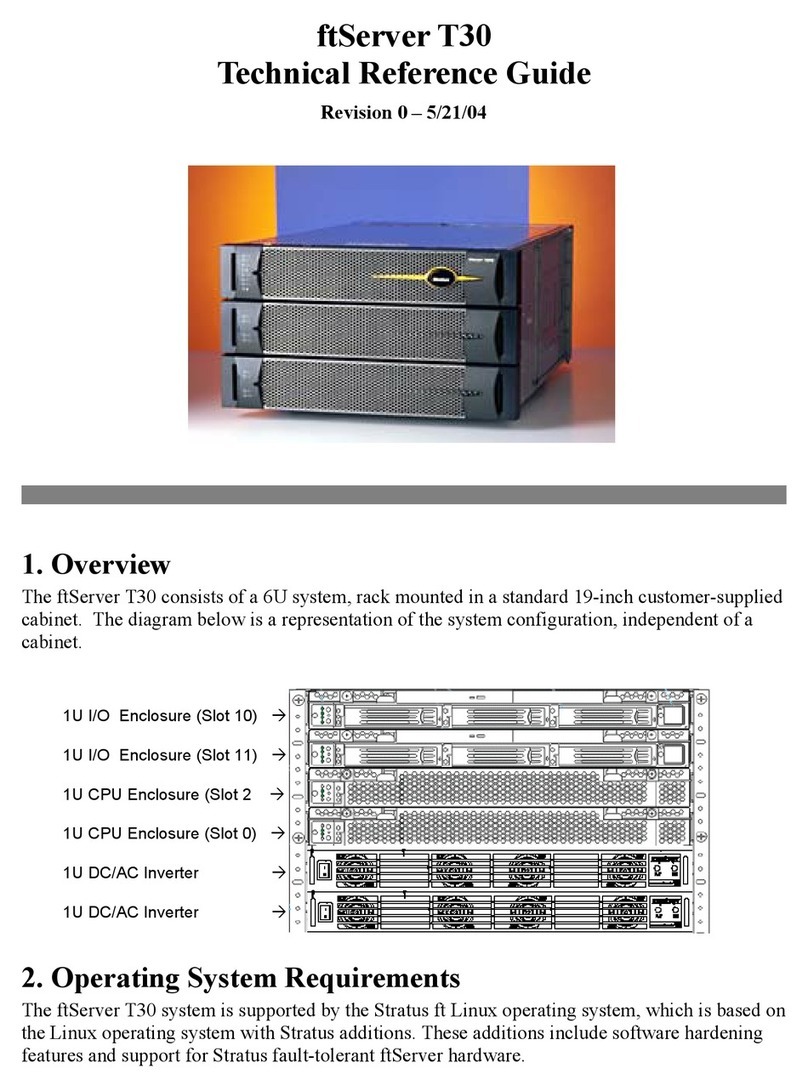
Stratus ftServer T30 Use and care manual
Stratus
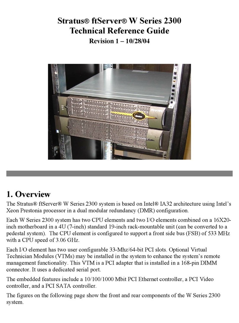
Stratus ftServer W 2300Series Use and care manual
Stratus
Stratus ftServer 2900 Series Technical manual

Stratus
Stratus ftserver 3300 Technical manual
Stratus
Stratus ftServer 2500 Technical manual
Stratus
Stratus ftServer 2600 Instruction Manual

Stratus
Stratus V 6624 Manual
Stratus
Stratus ftServer V 2302 Technical manual
Stratus
Stratus ftServer 2510 Technical manual

