Stratus V 6624 Manual

Stratus Technologies
R005S-00
Stratus ftServer V 6624
Hardware Installation Guide

Notice
The information contained in this document is subject to change without notice.
UNLESS EXPRESSLY SET FORTH IN A WRITTEN AGREEMENT SIGNED BY AN AUTHORIZED
REPRESENTATIVE OF STRATUS TECHNOLOGIES, STRATUS MAKES NO WARRANTY OR REPRESENTATION
OF ANY KIND WITH RESPECT TO THE INFORMATION CONTAINED HEREIN, INCLUDING WARRANTY OF
MERCHANTABILITY AND FITNESS FOR A PURPOSE. Stratus Technologies assumes no responsibility or obligation
of any kind for any errors contained herein or in connection with the furnishing, performance, or use of this document.
Software described in Stratus documents (a) is the property of Stratus Technologies Bermuda, Ltd. or the third party,
(b) is furnished only under license, and (c) may be copied or used only as expressly permitted under the terms of the
license.
Stratus documentation describes all supported features of the user interfaces and the application programming
interfaces (API) developed by Stratus. Any undocumented features of these interfaces are intended solely for use by
Stratus personnel and are subject to change without warning.
This document is protected by copyright. All rights are reserved. Stratus Technologies grants you limited permission to
download and print a reasonable number of copies of this document (or any portions thereof), without change, for your
internal use only, provided you retain all copyright notices and other restrictive legends and/or notices appearing in the
copied document.
Stratus, the Stratus logo, ftServer, the ftServer logo, Continuum, StrataLINK, and StrataNET are registered trademarks
of Stratus Technologies Bermuda, Ltd.
The Stratus Technologies logo, the Continuum logo, the Stratus 24 x 7 logo, ActiveService, ftScalable, and ftMessaging
are trademarks of Stratus Technologies Bermuda, Ltd.
RSN is a trademark of Lucent Technologies, Inc.
All other trademarks are the property of their respective owners.
Manual Name: Stratus ftServer V 6624 Hardware Installation Guide
Part Number: R005S
Revision Number: 00
Software Release Number: OpenVOS Release 19.0.0
Publication Date: September 2016
Stratus Technologies, Inc.
5 Mill and Main Place, Suite 500
Maynard, Massachusetts 01754-2660
© 2016 Stratus Technologies Bermuda, Ltd. All rights reserved.

Contents iii
Contents
Preface ix
1. Unpacking and Positioning the Cabinet 1-1
Safety Considerations 1-1
Safety Notices 1-2
Required Tools 1-3
Unpacking the Cabinet 1-3
Moving the Cabinet to the Installation Site 1-6
Removing the Packing Materials 1-7
Setting Up the Pallet Ramp 1-14
Removing the Cabinet from the Pallet 1-16
Inspecting the Cabinet and System 1-17
Verifying the Stratus Serial Number 1-17
Stabilizing the System 1-18
Disposing of Shipping Materials 1-19
2. Connecting and Powering On the System 2-1
Connecting External Components to the System 2-1
Connecting the RSN Console Server and Optional Modem 2-1
Connecting the AA-E97900 RSN Console Server to
the Internet 2-2
Connecting the AA-E97900 RSN Console Server to
a Modem 2-5
Connecting the ftScalable Storage System 2-8
Connecting the PC Console 2-9
Connecting the UPS 2-12
Installing the Optional Tape-Drive Enclosures 2-13
Installing the Optional Tape-Drive Enclosure 2-14
Powering On the System 2-17
Powering On the Components 2-17
Powering On the ftServer System 2-21
Related Documentation 2-22

Contents
iv Stratus ftServer V 6624 Hardware Installation Guide (R005S)
Appendix A. Removing and Replacing a U779V Fabric Switch A-1
Removing a U779V Fabric Switch A-1
Replacing a U779V Fabric Switch A-11
Final Steps A-21
Logging In to the Fabric Switch A-21
Stopping and Restarting the storage_monitor
Daemon A-22
Additional Information A-23

Figures v
Figures
Figure 1-1. Cabinet Packaged for Shipping 1-4
Figure 1-2. Dimensions of Packaged 38U Cabinet 1-5
Figure 1-3. Clearances Required at Installation Site 1-5
Figure 1-4. Cutting Exterior Shipping Straps 1-8
Figure 1-5. Removing Packing Material 1-9
Figure 1-6. Unbuckling Interior Shipping Straps 1-10
Figure 1-7. Wooden-Restraint Blocks 1-11
Figure 1-8. Inserting Lever Bar 1-12
Figure 1-9. Tilting Cabinet 1-13
Figure 1-10. Sliding Back Wooden-Restraint Blocks 1-13
Figure 1-11. Removing Bolt 1-14
Figure 1-12. Assembling and Positioning Ramp 1-15
Figure 1-13. Attaching Transition Plates 1-16
Figure 1-14. Moving Cabinet Down Pallet Ramp 1-17
Figure 1-15. Equipment Label 1-18
Figure 2-1. AA-E97900 RSN Console Server Serial Connection 2-2
Figure 2-2. AA-E97900 RSN Console Server Connections to the
Internet 2-3
Figure 2-3. Connecting the AA-E97900 Power Cord and Cables in
an Internet Connection 2-4
Figure 2-4. AA-E97900 RSN Console Server Connections to a
Modem 2-6
Figure 2-5. Connecting the AA-E97900 RSN Console Server Cables
and Power 2-7
Figure 2-6. Connecting PC Console to COM 2 Port 2-10
Figure 2-7. Connecting PC Console to U772 Ethernet Switch B 2-11
Figure 2-8. Connecting UPS Units to U772 Ethernet Switches 2-13
Figure 2-9. Attaching the Rails to the Tape-Drive Enclosure 2-14
Figure 2-10. Inserting the Enclosure into the Cabinet 2-15
Figure 2-11. Installing the Tape-Drive Enclosure 2-16
Figure 2-12. Powering On PDUs 2-18
Figure 2-13. Power Supply Unit 2-19
Figure 2-14. AC Power Cord 2-20
Figure 2-15. Powering On Fibre Channel Tape Drive 2-21
Figure 2-16. Powering On System 2-21
Figure A-1. Removing Bezel from Fabric Switch A-2
Figure A-2. Removing Air-Flow Bracket A-3
Figure A-3. Turning Off Power A-4

Figures
vi Stratus ftServer V 6624 Hardware Installation Guide (R005S)
Figure A-4. Disconnecting Cables at Front of Fabric Switch A-6
Figure A-5. Removing Power Cords from the Fabric Switch A-7
Figure A-6. Inserting the 1U Foam Spacer A-8
Figure A-7. Removing Screws at Rear of Cabinet A-9
Figure A-8. Removing Screws at Front of Cabinet A-10
Figure A-9. Sliding Fabric Switch Out of Cabinet A-11
Figure A-10. Attaching the Side Rails A-12
Figure A-11. Inserting Fabric Switch A-13
Figure A-12. Attaching Screws at Front of Cabinet A-14
Figure A-13. Attaching Screws at Rear of Cabinet A-15
Figure A-14. Checking the Power Switches A-16
Figure A-15. Attaching Power Cords to Fabric Switch A-17
Figure A-16. Installing Air-Flow Bracket A-18
Figure A-17. Attaching Cables to Fabric Switch A-19
Figure A-18. Replacing Bezel A-20

Tables
viii Stratus ftServer V 6624 Hardware Installation Guide (R005S)

Preface ix
Preface
The Stratus ftServer V 6624 Hardware Installation Guide (R005S) documents the
hardware installation procedures for Stratus ftServer V 6624 systems.
This manual is intended for Customer Service personnel who are installing these
systems. Because the internal components of an OpenVOS ftServer system are
installed before arriving at a customer site, this manual documents only the procedures
necessary for setting up a customer system.
Revision Information
This is a new manual.
Notation Conventions
This document uses the notation conventions described in this section.
Warnings, Cautions, Notices, and Notes
Warnings, cautions, notices, and notes provide special information and have the
following meanings:
WARNING
!
A warning indicates a hazardous situation that, if not
avoided, could result in death or serious injury.
AVERTISSEMENT
!
Unavertissementindiqueunesituationdangereusequi,si
pas évitée, pourrait entraîner la mort ou des blessures
graves.
CAUTION
!
A caution indicates a hazardous situation that, if not
avoided, could result in minor or moderate injury.

Preface
xStratus ftServer V 6624 Hardware Installation Guide (R005S)
MISE EN GARDE
!
Une mise en garde indique une situation dangereuse qui,
si pas évitée, pourrait entraîner des blessures mineures
ou modérées.
NOTICE
A notice indicates information that, if not acted on, could
result in damage to a system, hardware device, program,
or data, but does not present a health or safety hazard.
NOTE
A note provides important information about the operation
of an ftServer system or related equipment or software.
Typographical Conventions
This document uses the following notation conventions.
Italics introduces or defines new terms. For example:
The master disk is the name of the member disk from which the module was
booted.
Boldface emphasizes words in text. For example:
Every module must have a copy of the module_start_up.cm file.
Monospace represents text that would appear on your terminal’s screen (such as
commands, subroutines, code fragments, and names of files and directories).
For example:
change_current_dir (master_disk)>system>doc
Monospace italic represents terms that are to be replaced by literal values. In the
following example, the user must replace the monospace-italic term with a literal
value.
list_users -module module_name

Preface
Preface xi
Monospace bold represents user input in examples and figures that contain both
user input and system output (which appears in monospace). For example:
display_access_list system_default
%dev#m1>system>acl>system_default
w *.*
Getting Help
If you have a technical question about ftServer system hardware or software, try these
online resources first:
Online documentation at the StrataDOC Web site. Stratus provides
complimentary access to StrataDOC, an online-documentation service that
enables you to view, search, download, and print customer documentation. You
can access StrataDOC at the following Web site:
http://stratadoc.stratus.com
Online support from Stratus Customer Service. Youcan findthe latesttechnical
information about an ftServer system through online product support at the
Customer Support Web site:
http://www.stratus.com/go/support
You can enter the Service Portal from this Web site by clicking Service Portal and
then logging in.
If you are unable to resolve your questions with the help available at these online sites,
and the ftServer system is covered by a service agreement, please contact the Stratus
Customer Assistance Center (CAC) or your authorized Stratus service representative.
For information about how to contact the CAC, see the following Web site:
http://www.stratus.com/go/support
Commenting on This Manual
You can comment on this manual using one of the following methods. When you
submit a comment, be sure to provide the manual’s name and part number, a
description of the problem, and the location in the manual where the affected text
appears.
From StrataDOC, click the site feedback link at the bottom of any page. In the
pop-up window, answer the questions and click Submit.
From any email client, send email to [email protected].
Stratus welcomes any corrections and suggestions for improving this manual.

Preface
xii Stratus ftServer V 6624 Hardware Installation Guide (R005S)
Regulatory Notice
All regulatory notices are provided in the site planning guide for your system.

Unpacking and Positioning the Cabinet 1-1
Chapter 1
Unpacking and Positioning the Cabinet1-
This chapter discusses the following topics:
“Safety Considerations” on page 1-1
“Safety Notices” on page 1-2
“Required Tools” on page 1-3
“Unpacking the Cabinet” on page 1-3
“Moving the Cabinet to the Installation Site” on page 1-6
“Removing the Packing Materials” on page 1-7
“Setting Up the Pallet Ramp” on page 1-14
“Removing the Cabinet from the Pallet” on page 1-16
“Inspecting the Cabinet and System” on page 1-17
“Verifying the Stratus Serial Number” on page 1-17
“Stabilizing the System” on page 1-18
“Disposing of Shipping Materials” on page 1-19
Safety Considerations
To ensure a safe and effective installation, follow the procedures exactly as they are
written in this manual. Before installing the system, take the following important
precautions:
Do not attempt to install the system without the assistance of another able-bodied
person. The size and weight of the system do not allow it to be safely installed by
one person.
The information in this manual assumes that the system site has been prepared
according to the instructions in the following manuals:
–Stratus ftServer V 6624 System: Site Planning Guide (R763)
–Stratus ftServer V 6624 System: Operation and Maintenance (R764)
–Stratus ftServer Systems: Peripherals Site Planning Guide (R582)

Safety Notices
1-2 Stratus ftServer V 6624 Hardware Installation Guide (R005S)
See these manuals before proceeding with the installation.
Observe all applicable industry safety standards. See “Safety Notices” on
page 1-2.
Provide the necessary space and light to safely perform the installation.
Do not wear conductive objects, such as rings, bracelets, and keys.
Safety Notices
WARNING
!
Risk of explosion if battery is replaced by an incorrect
type. Dispose of used batteries according to the
instructions provided with the battery.
WARNING
!
If you receive locking power cords with your system, do
notsubstituteother power cords.Use ofthe locking power
cords ensures proper grounding of the system.
WARNING
!
Depending on the configuration, the system uses two or
four power cords to provide redundant sources of power.
To fully remove power from a system, disconnect all
power cords. To reduce the risk that electrical shock could
injure a person or damage the system, exercise caution
when working in the unit even when only one power cord
is connected.
WARNING
!
To prevent a cabinet from tipping over and injuring a
person or damaging the system, start installing systems
from the bottom of the cabinet upward.
WARNING
!
If you replace the modem cable supplied by Stratus, use
a cable with a gauge of at least 26 AWG to prevent fire.

Required Tools
Unpacking and Positioning the Cabinet 1-3
Required Tools
To install the system, the following tools are necessary:
#2 Phillips screwdriver
Scissors or utility knife
Metal shears to cut pallet straps
3/8” drive ratchet with 9/16” socket
Open-ended 9/16” box wrench
Assorted open-end and/or box wrenches
ESD static kit
Assorted tie wraps
Unpacking the Cabinet
The cabinet-mounted system is enclosed in a cardboard shipping container, which is
secured to a shipping pallet by exterior tie-down straps. (Inside the cardboard, interior
straps secure the cabinet to the pallet.) A ramp for rolling the cabinet off the pallet is
attached to the front of the shipping container, along with two transition plates, which
you use to secure the ramp to the pallet. A lever bar is secured to the ramp, for use in
tipping the cabinet to remove it from the pallet. Labels on the cardboard cap indicate
the front and rear of the cabinet.
Figure 1-1 shows a shipping container for a 38U cabinet that contains one or more
systems and optional components. (“U,” for unit, equals 1.75 inches (in.), or 4.45
centimeters (cm).)

Unpacking the Cabinet
1-4 Stratus ftServer V 6624 Hardware Installation Guide (R005S)
Figure 1-1. Cabinet Packaged for Shipping
1. Check the packing list to verify that you have received the correct shipment.
2. Verify that the Shockwatch indicators on the outer sides of the shipping container
have not been activated.
NOTICE
If you received the wrong shipment, or if a handling
indicator has been activated, do not proceed with the
unpacking. Contact the CAC immediately.
3. Verify that the area through which you must move the system has adequate
clearance, as the following figures indicate:
Figure 1-2 shows the dimensions of a packaged 38U cabinet.
Figure 1-3 shows the clearances required at the installation site.
Include the height of the pallet jack when you calculate the overall system height.
upk001a
Ramp
Pallet
Tie-down
Straps
Transition
Plates
Lever Bar

Unpacking the Cabinet
Unpacking and Positioning the Cabinet 1-5
Figure 1-2. Dimensions of Packaged 38U Cabinet
Figure 1-3. Clearances Required at Installation Site
upk002a
80 in.
(2m)
41 in.
(104.14 cm)
53 in.
(134.62 cm)
5 in.
(12.7 cm)
38U Cabinet
msys046
Cabinet
on Pallet
Pallet Ramp
Unload From
This End
42 in.
(107 cm)
42 in.
(107 cm)
150 in.
(381 cm)
42 in.
(107 cm)

Moving the Cabinet to the Installation Site
1-6 Stratus ftServer V 6624 Hardware Installation Guide (R005S)
If the corridor and door dimensions are large enough to accommodate the
unpacked cabinet still tied to its pallet, use a pallet jack to move it from the delivery
site to the installation site, as described in “Moving the Cabinet to the Installation
Site” on page 1-6.
If the corridor and door dimensions are too small to accommodate the unpacked
cabinet still tied to its pallet, unpack the cabinet and unload it from the pallet before
you move it to the installation site. In this case, use the pallet jack to move the
unpacked cabinet as close to the installation site as possible. Then, unpack the
cabinet, remove it from its pallet, and roll it carefully on its casters to the installation
site.
Moving the Cabinet to the Installation Site
WARNING
!
To avoid personalinjuryordamageto the system,two
persons are required to move, unpack, and install an
ftServer system. Because of the size and weight of
ftServer systems, have professional movers deliver and
move the packaged units to the installation site.
NOTICE
To prevent or minimize condensation on the system’s
internal and external surfaces, avoid exposing the system
to extreme temperature and/or humidity changes when
moving it to the installation site. If the system has been
exposed to extreme temperature or humidity conditions
during transit, or if condensation is present, see the
section “Stabilizing the System” on page 1-18 for
stabilization guidelines.
When shipped, the system cabinet is tied to the pallet beneath it. The pallet has a
clearance for a pallet jack to move the unit. When moving a system, follow these
guidelines:
1. Verify that the unpacked system is still secured to the pallet.
2. Use a pallet jack to move the system on its pallet to the installation site.

Removing the Packing Materials
Unpacking and Positioning the Cabinet 1-7
NOTICE
Use a pallet jack, not a forklift, to move the packaged
system.Usinga forkliftcoulddamagethesystem.Usethe
pallet jack at the front or rear of the cabinet.
3. Position the cabinet pallet so that it has the clearances shown in Figure 1-3.
Removing the Packing Materials
WARNING
!
To avoid personalinjuryordamage to thesystem,two
persons are required to perform the following
procedures.
1. Orient the system package so that the package and the ramp have, as a minimum,
the clearance shown in Figure 1-3. Also, verify that you have enough clearance
above the system to remove the top cardboard cap.
2. With one person holding the ramp in place, use the metal shears to cut the exterior
shipping straps. To avoid injury while cutting each strap, hold the strap firmly
with one hand as you stand away from it. See Figure 1-4.
WARNING
!
The shipping straps snap with considerable force when
they are cut! To avoid eye or skin injuries, use caution
when cutting the shipping straps.

Removing the Packing Materials
1-8 Stratus ftServer V 6624 Hardware Installation Guide (R005S)
Figure 1-4. Cutting Exterior Shipping Straps
3. Remove the ramp. Behind the ramp are two accessory boxes, which contain
variouscomponentsand documentation. Removetheboxesandsetthemaside for
later use.
NOTE
It is possible that the system will include only one
accessory box.
4. Remove the cardboard pieces of packing material surrounding the cabinet (see
Figure 1-5). These pieces include two C-fold sleeves around the sides of the
cabinet and a cap at the top.
upk003a
Table of contents
Other Stratus Server manuals

Stratus
Stratus ftServer V 2302 Manual
Stratus
Stratus ftServer 2510 Technical manual
Stratus
Stratus ftServer 2600 Instruction Manual
Stratus
Stratus ftServer 2900 Series Technical manual
Stratus
Stratus ftServer V 2302 Technical manual
Stratus
Stratus ftServer 2500 Technical manual

Stratus
Stratus ftServer 3000 Series Technical manual
Stratus
Stratus ftServer 2600 Technical manual
Stratus
Stratus ftServer W 2300Series Use and care manual
Stratus
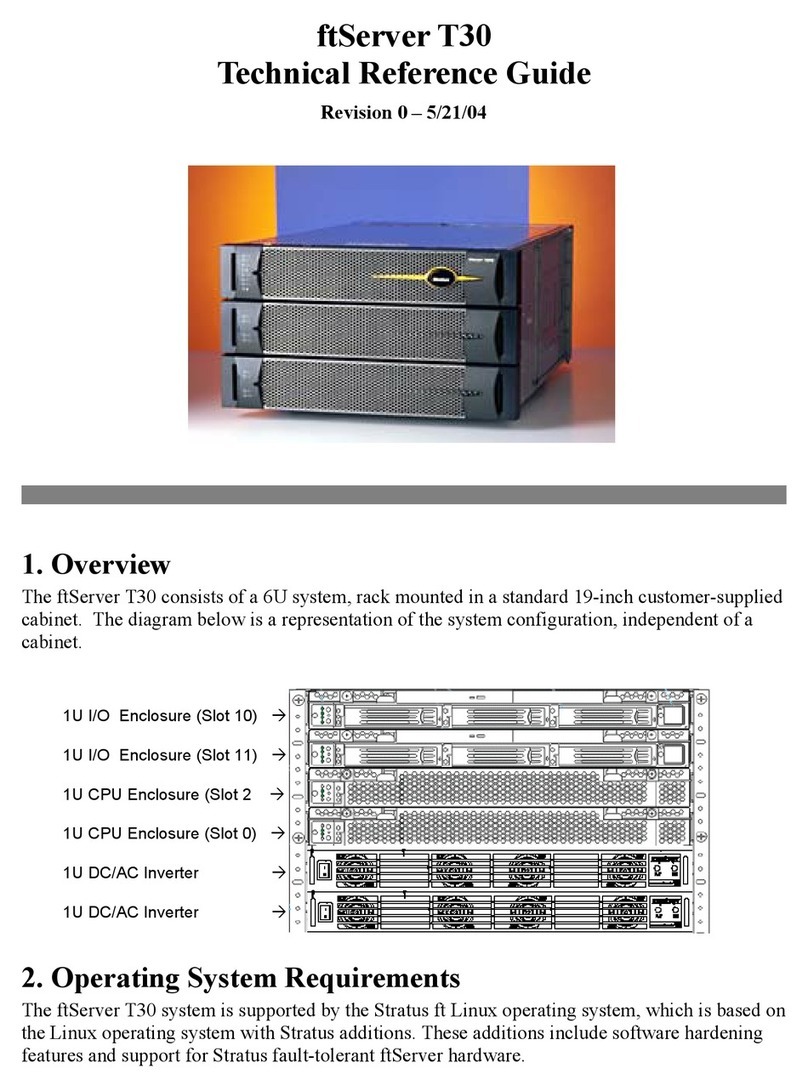
Stratus ftServer T30 Use and care manual


