strex STB-150 User manual

STREX Cell Strain Instrument
Cat. # STB-150
User Manual
Cell Stretching System
Model # STB-190-XY
User Manual
Strex US Office
10060 Carroll Canyon Rd., Suite 100
San Diego, CA 92131
Email: info@strexcell.com
www.strexcell.com

Section 1: Main Components
Cell Strain Instrument (Stretch Unit)
Silicone Strain Chamber (STB-CH-04)
Strain chamber brackets
Each chamber is
mounted on
four brackets
Fan
Chamber Length Adjustment
Knob:
To freely rotate the knob, the
power switch must be OFF. Use
the knob to adjust the distance
of the chamber brackets such
that it maintains tension on the
silicone chamber.
Motor Cable
Cable connects to Control Unit
Platform
Place platform ontop of
microscope stage for viewing.
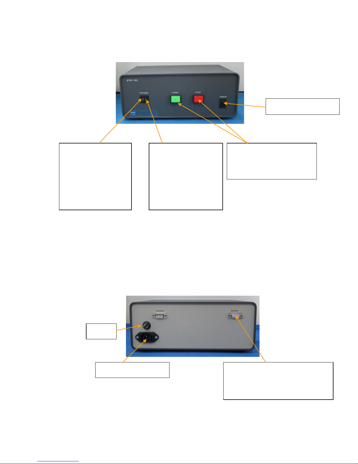
Main Power Switch
Frequency
Selector (left digit)
Use upper and lower
buttons to adjust
frequency
Start and Stop Button
Use to start or stop the
stretching action.
Stretch Ratio
Selector (right
digit)
Use upper and lower
buttons to increase
and decrease strain
ratio.
Control Unit Front Panel
Control Unit Back Panel
Motor Cable Outlet
Connects the Stretch Unit to the
Control Unit via Motor Cable
Fuse
Power Cable Outlet

Section 2: Use of the Cell Strain Instrument
Preparation of the Cell Strain Instrument
Before using the Stretch Unit, sterilize the unit —especially the chamber mounting area —
using ethanol-immersed swabs.
System Operation
Operation of the Cell Strain Instrument is very straight forward and intuitive. Below are the
basic steps to use this instrument. The step motor that moves the chamber brackets is
made to operate 15 minutes continuously. It is not recommended to extend the use
of the motor beyond 15 continuous minutes because of possibly overheating and
burning out the motor.
►Set-up the Stretch Unit and Control Unit
1. Connect the Stretch Unit to the Control Unit by the Motor Cable. This supplies electricity
to the Stretch Unit and enables the two units to communicate.
2. Connect the Control Unit to the power supply (240 V) by the Power Cable.
3. Turn on the Power Switch to start operation. The Power Switch will light up and the Stop
Button will flash.
BEWARE: The Fan that cools the step motor will be rotating. Do not obstruct the fan
blades with any objects.
4. If the electrical system is operating properly, turn OFF the Power Switch.
5. Make sure that the microscope is level on the work bench and the Stretch Unit is level
on the microscope stage.
►Start Cell Stretching
1. Make sure that the electrical/communications for the Stretch and Control Units are
properly set up.
2. Load the chambers into the Stretch Unit by inserting the pins on the bracket into the four
corners of the chamber. The Power Switch must be OFF to freely rotate the
Chamber
Length Adjustment Knob.
3. Rotate the Chamber Length Adjusting Knob counterclockwise to create tension on the
chamber. The membrane at the bottom of the chamber should be taut.
4. Turn on the Power Switch.

5. Select the desired stretch ratio and frequency on the Control Unit. Programs are
outlined in Section 3.
6. Press the START button to start the stretch cycle. During the action cycle, the green
light will be illuminated. To STOP movement at any time, press the STOP button.
7. Do not change the Stretch Ratio or Frequency parameters during the operation of
a stretch cycle. Press the STOP button and wait for the program to complete the
final stretch-contract sequence (returning to the original start position) before
initiating the next stretch parameter. Changing parameters during a stretch cycle may
damage the motor.
8. After a few minutes of running a stretch program, stop the cycle and check the condition
of the cells. If the cells have not detached from the membrane, proceed with your
experiment. If the cells are detached, the chamber coating was probably insufficient.
Recoat the chambers.
Culturing Cells in the Silicone Chambers
1. Seed cells at the appropriate concentration in a freshly coated chamber.
Important: It is critical to not over expose the cells to dissociation enzymes. Cells should
be treated in the same manner (type and concentration of enzyme, temperature, and
exposure time) for all experiments.
Important: Cells should not be seeded at a high density in the chambers. For example,
epithelial cells often form a cell-sheet and the cell-cell adhesion seems to be stronger
than a cell-surface adhesion. When this happens cells may detach from the chamber.
Additionally, cultures that are grown over a week in the chambers may detach.
2. After an overnight incubation without stretching, inspect the cells with a microscope to
ensure they have adhered to the chamber.
Preparation of Silicone Chambers
Before using the chambers, they should be sterilized and coated with a cell adhesion
matrix. The coating procedures can be adapted for use with other matrices, such as
elastin, pronectin, and laminin.
Sterilize the chambers in an autoclave for 20 minutes at 121°C. The silicone chambers can
withstand temperatures up to 180°C. Use of an autoclave is preferable. However, if an
autoclave is not available, the chambers may be sterilized by submerging them in 70%
ethanol, rinsing with water, then drying in a sterile environment.
Place the sterile chambers in a Petri dish in preparation for coating.
The PDMS (silicone) chamber is very hydrophobic with two methyl-bases on the surface; therefore the chamber
must be coated with a cell adhesion matrix such as fibronectin or collagen. In the presence of fibronectin or
collagen, cells adhere to the matrix by integrins. Integrin attachment is a cell specific interaction unlike cell
attachment to plastic or glass dishes, where cells non-specifically attach due to a charged surface.

►Fibronectin Coating
Preparation of fibronectin solution:
1. Dilute human or bovine fibronectin to a final concentration of 50 to 100 µg/ml in
Phosphate Buffered Saline (PBS)
Coating with fibronectin solution:
1. Pour 3 ml of the fibronectin solution into each strain chamber
2. Incubate at 37 °C for more than 30 minutes
3. Aspirate the fibronectin solution. If coating is successful, water will not be repelled after
removing the fibronectin solution.
4. The liquid solution can be used to coat 3 or 4 chambers before discarding.
►Gelatin Coating
Preparation of gelatin solution:
1. Add gelatin powder to PBS at a concentration of 2%
2. Autoclave the mixture to dissolve and sterilize
Coating with gelatin solution:
1. Pour 3 ml of the gelatin solution into each strain chamber
2. Incubate at 37oC for more than 30 minutes
3. Aspirate the gelatin solution. If coating is successful, water will not be repelled after
removing the gelatin solution.
4. The liquid solution can be used to coat 3 or 4 chambers before discarding.
►Collagen Coating (Cellmatrix 1-C, P, Type 3 or 4)
Preparation of collagen solution:
1. Combine 1 part collagen to 10 parts HCL, pH 3, in a sterile tube
Coating with collagen solution:
1. Coat chamber with a thin layer
2. Aspirate excess
3. Dry in biological safety cabinet at 25°C or below. The chamber can be stored at the
same
temperature.
4. Wash the chamber twice with culture medium.
5. If coating is successful, water will not be repelled.
Important: If cells are having difficulty attaching to the freshly coated chambers or are
easily detaching upon stretching, treat the chamber with a higher concentration of the

extra-cellular matrix or coat overnight.
Section 3: Strain Parameters
Standard Program
Digit Degree of stretch Distance
0 2% 0.4mm
1 4% 0.8mm
2 6% 1.2mm
3 8% 1.6mm
4 10% 2.0mm
5 12% 2.4mm
6 15% 3.0mm
7 20% 4.0mm
Digit Program Description
0 1cycle stretch-hold indefinitely
1 1cycle
Square wave
Stretch 0.5 seconds-hold 1 second-contract 0.5 second-end
2 1cycle
Square wave
Stretch 0.5 seconds-hold 3 second-contract 0.5 second-end
3 1cycle
Square wave
Stretch 0.5 seconds-hold 10 second-contract 0.5 second-end
4 1cycle/min
Square wave
Stretch 0.5 seconds-hold 29.5 second-contract 0.5 second-hold 29.5
seconds-repeat
5 6cycle/min
Square wave
Stretch 0.5 seconds-hold 4.5 second-contract 0.5 second-hold 4.5 seconds-
repeat
6 20cycle/min
Square wave
Stretch 0.5 seconds-hold 1 second-contract 0.5 second-hold 1 seconds-
repeat
7 60cycle/min*
Square wave
Stretch 0.5 seconds - contract 0.5 second-repeat
*60 cycles/minute is the maximum speed at which the instrument can operate.
At this speed 60 cycles/minute, square pattern does not have a hold time and the pattern becomes
the same as a sinusoidal pattern.
LEFT Digit: Frequency Selector
RIGHT Digit:
Stretch Ratio Selector

Inquire for faster speeds.
Section 4: FAQ
Q1: What are the characteristics of the silicone chamber?
A1: The strain chamber is made from silicone elastomer consisting of polydimethylsiloxane as its
major component. The chamber surface is strongly hydrophobic and cells have difficulty
attaching to it; therefore, the chamber surface should be coated with an extra-cellular matrix like
fibronectin, collagen, laminin, or gelatin before cultivation.
Q2: Cell attachment on the stretch chamber is not consistent.
A2: There may be wrinkles or bubbles on the bottom surface of the strain chamber when seeding
cells. Although the chamber is carefully made not to have wrinkles on it, some products might
have little wrinkles due to its thin structure. We recommend the following steps. Using a Petri
dish that is large enough to hold the chamber, add a small volume of ethanol. Place one end of
the chamber in the ethanol and lay the chamber down by slowly moving toward the opposite
end of the chamber without trapping air bubbles between the dish and the chamber. The thin
layer of ethanol between the dish and the chamber will remove any wrinkles in the chamber
membrane. Allow the ethanol to evaporate before spreading your cell suspension in the
chamber.
Q3. Cell attachment on the stretch chamber was confirmed by microscopy. But the cells detached
from the chamber surface after stretching the cells.
A3: Try seeding your chambers at a lower concentration of cells. In typical cell culture dishes, over-
confluent cells generally adhere to neighboring cells rather than to the base matrix (dish
surface). This behavior is exaggerated when an excess number of cells are seeded into a
stretch chamber.
A second possibility for cell detachment is that the cells were damaged by enzyme treatment such
as trypsin.
The damaged cells may attach to surfaces by non-specific binding and are not specifically bound
to the extra-cellular matrix coating on the chamber; therefore, time, concentration, and temperature
for the enzyme treatment should be optimized to reduce cell damage.
A third possibility is insufficient coating of the chamber preventing the cells from attaching to the
chamber. In this case, longer coating time is recommended.
Some researchers coat the chamber with two or more kinds of the extra-cellular matrix materials to

increase binding effectiveness.
Q4: How long can cells be stretched?
A4: The duration depends on cell strain and condition. However, the step motor in a STB-150 and
STB-190XY is made to operate for 15 continuous minutes. The STB-140 models can run for
hours to days if the cooling system is on.
Q5: How can I obtain protein or mRNA samples from the cells attached to the silicone membrane?
A5: (1) Proteins for Western blotting: Wash the cells once with PBS. Add SDS-PAGE sample
loading dye directly into the chamber, and collect the cell extract by using a cell scraper.
(2) Proteins for Immunoprecipitation: Wash the cells once with PBS. Add cell extract buffer
directly into the chamber, and collect the cell extract by using a cell scraper.
(3) RNA: Wash the cells once with PBS (for RNA preparation). Add RNA extraction buffer
directly into the chamber, and collect the cell extract by using a cell scraper.
Q6: I want to use recombinant cells for an experiment.
A6: Direct transfection of cells in the chamber may be possible. However, transfection itself may
damage the cells, which may make getting clear image data difficult. We recommend
performing the transfection in a standard culture dish then transferring the recombinant cells
into the strain chamber.
Q7: Cells seem to be crowded in the center instead of being uniformly distributed throughout the
chamber.
A7: Vibration from the incubator may disrupt the distribution of the cells. We recommend gently
rocking the chamber 15 mins after seeding your cells.

Section 5: References
1. Effects of repetitive stretch stimulation on neonatal rat cardiocytes in vitro, K. Kada, K. Yasui, K.
Naruse, and J. Toyama. Environmental Medicine, 40: 69-72, 1996.
2. Inhibitory action of repeated stretch stimulation on apoptosis in neonatal rat cardiocytes., K. Yasui, H.
Shimano, K. Kada, K. Naruse, and J. Toyama. Environmental Medicine, 40: 175-177, 1996.
3. Mechanosensitive ion channels: Single channels vs. Whole cell activities, M. Sokabe, K. Nunogaki
and K.Naruse. Progress in Cell Research, 6:139-149, 1997.
4. Up-regulation of integrin beta3 expression by cyclic stretch in human umbilical endothelial cells., M.
Suzuki, K. Naruse, Y. Asano, T. Okamoto, N, Nishikimi, T. Sakurai, Y. Nimura, and M. Sokabe.
Biophys. Biochem. Res.Com., 239:372-376, 1997.
5. Mechanotransduction and intracellular signaling mechanisms of stretch-induced remodeling in
endothelialcells, Masahiro Sokabe, Keiji Naruse, Shorei Sai, Takako Yamada, Keisuke Kawakami,
Masumi Inoue,Kichiro Murase and Motoi Miyazu. Heart Vessel, S12:191-193, 1997.
6. Involvement of SA channels in orienting response of cultured endothelial cells to cyclic stretch., K.
Naruse, Y.Yamada, and M. Sokabe. Am. J. Physiol., 274:H1532-H1538, 1998.
7. Up regulation of COX expression by uni-axial cyclic stretch in human lung fibroblast cells, T. Kato, N.
Ishiguro, H. Iwata, T. Kojima, T. Ito and K. Naruse. Biophys. Biochem. Res.Com., 244:615-619, 1998.
8. Pp125FAK is required for stretch dependent morphological response of endothelial cells. K. Naruse, T.
Yamada, X. Sai, M. Hamaguchi, and M. Sokabe. Oncogene, 17:455-463, 1998.
9. Orientation Change of Cardiocytes Induced by Cyclic Stretch Stimulation: Time Dependency and
Involvement of Protein Kinases, K. Kada,K. Yasui, K. Naruse, and J. Toyama, J. Mol. Cell. Cardio.,
31:247-259, 1999.
10. Molecular Identification of a Eukaryotic Stretch-Activated Nonselective Cation Channel, M. Kanzaki,
M.Nagasawa, I. Kojima, C. Sato, K. Naruse, M. Sokabe, H. Iida, Science, 285:882-886, 1999.
11. Activation of pp60SRC is Critical for Stretch-Induced Orienting Response in Fibroblasts, X. Sai, K.
Naruse, M.Sokabe, J. Cell Sci. 12:1365-1373, 1999.
12. SA Channel Mediates Superoxide Production in HUVECs, K. Aikawa, N. Nishikimi, T. Sakurai, Y.
Nimura, M. Sokabe, K. Naruse, Life Sci. 69 (15):1717-1724, 2001.
13. Uni-axial cyclic stretch induces the activation of transcription factor nuclear factor κΒ in human
fibroblast cells, H. Inoh, N. Ishiguro, S. Sawazaki, H. Amma, M. Miyazu, H. Iwata, M. Sokabe, K.
Naruse, FASB Journal, 16:405-407, 2002.
14. Mechanical stress-dependent secretion of interleukin 6 by endothelial cells after portal vein
embolization:clinical and experimental studies, M. Kawai, K. Naruse, S. Komatsu, S. Kobayashi, M.
Nagino, Y. Nimura, M.Sokabe, J. Hepatol. 37(2):240-246, 2002.
15. Calcium regulates the P13K-Akt pathway in stretched osteoblasts, T. Danciu, R. Adam, K. Naruse,
M.Freeman, P. Hauschka, FEBS Letters 536:193-197, 2003.
16. A new mechanosensitive channel SAKCA and new MS channel blocker GsTMx-4, M. Sokabe, K.
Naruse, T. Qiong-Yao, Folia Pharmacologica Japonica 124(3):301-310, 2004.
17. Mechanotransduction of integrin is essential for IL-6 secretion from endothelial cells in response to

uniaxial continuous stretch, A. Sasamoto, M. Nagina. S. Kobayashi, K. Naruse, Y. Nimura, M.
Sokabe, Am J Physiol Cell Physiol 288:1012-1022, 2005.
18. N-cadherin-mediated cell adhesion determines the plasticity for cell alignment in response to
mechanical stretch in cultured cardiomyocytes, T. Matsuda, K. Takahashi, T. Nariai, T. Ito, T.
Takatani, Y. Jujio, J. Azuma, Biochem Biophys Res Comm 326:228-232, 2005.
19. N-cadherin signals through Rac1 determine the localization of connexin 43 in cardiac myocytes, T.
Matsuda, Y. Jujio, t. Nariai, T. Ito, M. Yamane, T. Takatani, K. Takahasi, J. Azuma, J Mol Cell Cardio
40(4):495-502, 2006.
20. Activation of a mechanosensitive BK channel by membrane stress crated with amphipaths, Mol
Membr Biol 22(6):519-527, 2005.
21. Stretch-induced cell proliferation is mediated by FAK-MAPK pathway, Life Sci 76(24):2817-2825,
2005.
22. Fabrication of reconfiguration protein matrices by cracking, X. Zhu, K. Mills, P. Peters, J. Bahng, El
Liu, J. Shim, K. Naruse, M. Csete, M. Thouless, S. Takayama, Nature Materials 4:403-406, 2005.
23. Involvement of reactive oxygen species in cyclic stretch-induced NF-κΒ activation in human
fibroblast cells, H. Amma, K. Naruse, N. Ishiguro, M. Sokabe, Brit J Pharmacol 145:364-373, 2005.
24. Viscoelastic and dynamic nonlinear properties of airway smooth muscle tissue: roles of mechanical
force and the cytoskeleton, S. Ito, A. Majumdar, H. Kume, K. Shimokata, K. Naruse, K. Lutchen, d.
Stamenovic, B. Suki, Am J Physiol Lung Cell Mol Physiol 290(6):L1227-1237, 2006.
25. Bi-phasic activation of eNOS in response to uni-axial cyclic stretch is mediated by differential
mechanisms in BAECs, H. Takeda, K. Komori, N. Nishikimi, Y. Nimura, M. Sokabe, K. Naruse, Life
Sci 79(3):233-239, 2006.
Section 6: Safety Precautions & Instructions
These Safety Precautions are to ensure that you use the product safely and correctly and
to prevent harm or injury to users and other people. To prevent injury or harm please read
and understand the below text.
WARNING
Indicates handling prior to reading may
cause serious injury or death.
CAUTION
Indicates handing prior to reading may
cause physical harm or damage.
Disclaimer
We are not responsible for any damage to equipment or facilities during the
installation, use, or removal of the product.
We are not responsible for damages caused by earthquakes, thunder, wind, fire,
flood, or a third party to the machine. Negligence, misuse, or abnormal conditions
resulting in damage are also not our responsibility.
We are not responsible for damages caused by malfunctions due to combinations
of equipment or software not involving Strex.
We are not responsible for any incidental damage caused by the use or misuse of
this product including loss of business income, interruption of business, loss of
stored data, theft of machine, etc.
WARNING
Please do not place water or water-containing vessels on or near the machine:
Cups, vials, tubes etc. containing water should not be located on or near the
device.
Be careful as to not wet the connection cable or power cable. Failure to do
so could lead to fire, electric shock etc. Do not disassemble or reconfigure.
Do not attempt to disassemble or reconfigure this machine. Doing so may
result in fire, electric shock, or equipment malfunction. Please do not use
under abnormal conditions.
If the machine is overheating, emitting a strange odor, etc. disconnect the
power cable from the outlet immediately. Failure to do so may result in a fire
or electric shock.
Do not use voltage other than the indicated power supply voltage. Failure to
do so may result in fire or electric shock. Be sure to use the supplied power
cable.

Do not exceed the rating of outlets and wiring equipment. If rating is
exceeded with the multiple electrical components fire may be caused due to
heat generation.
Do not touch the main unit or the power cable during severe weather
events. It may cause electric shock.
Do not damage the power cable, forcibly bend it, twist it or pull it. Also,
please do not place heavy or heated objects on the power cable. The power
cable may be damaged, causing fire, electric shock accident, etc.
Please contact your distributor to replace the power cable.
Do not handle power cable with wet hands. Be aware of foreign matter
entering instrument
Unplug the machine immediately if foreign matter, such as water or
excessive dust, is expected to have entered it to prevent risk of electric
shock. If you dropped or damaged the machine.
Unplug the power cable if the machine has been dropped or damaged. Not
doing so may result in electric shock.
CAUTION
Proper Handling of This Equipment
Do not place the power cable close to a heating source such as a hotplate or open
flame. The cable cover may melt, causing fire, electric shock, malfunction, etc.
When unplugging the power cable from the outlet, please do not pull on the cable
part, but remove at the plug. Pulling the cable will damage the cable and cause fire,
electric shock, breakdown, etc.
Regularly check the condition of the plug. If it is damaged or if dust gathers in the
plug insulation failure may result, causing fire. Also, if the plug is incompletely
inserted, it may cause electric shock or fire. Do not place heavy objects on top of
this machine.
If you place heavy objects on the machine, the items may collapse or fall and cause
injury.
Usage Notice
Periodically clean the plug and receptacle once a month and check that it is securely
inserted. When you are not using the machine for a long time, please be sure to unplug
the power cable from the outlet for safety.
Please read this section carefully before using the instrument. Items in this section alert
the user to operational dangers that, if not followed, may damage the instrument or, more

significantly, result in serious injury or death of the user. To ensure safe operation of the
instrument, it is therefore imperative that you follow these instructions carefully.
Power cable
To avoid possible short circuit, shock, or fire.
Only use the power cable provided with the Cell Strain Instrument.
Do not touch the cable with wet hands.
Do not use the machine with other voltage than that specified. In some cases, a
transformer may be used for compatibility. Inappropriate current may result in the
machine overheating, short-circuiting, and/or fire may occur.
Do not staple around the power cable.
Do not bend the cable or place heavy objects on it.
When pulling a connector from an outlet, pull to disconnect gently by holding its plug, not
the cable.
Do not plug many objects into a single electrical outlet since it may cause fire.
If you are using an extension cord, ensure it can withstand the total current to be used.
Disconnect power from the unit when it is not in use.
Connect the instrument to a power-surge protected outlet.
Installation Location and Environment
Keep the instrument on a stable, level floor or a table, secure from vibrations. Be sure
you have enough space.
Do not store the instrument in a humid or dusty place. Over time, excessive humidity or
dust may cause deterioration that can result in an electrical short-circuit and possibly fire.
Do not use the machine in a place where the temperature is excessively high. Do not
place and run the machine near a heater or in a place being exposed to direct sunlight.
To avoid possibly explosion, never place and run the instrument nearby the presence of
flammable solid substance, liquid, or gas. It may cause explosion or fire.
Use the machine in well-lit conditions.
Do not use the machine outdoors in direct sunlight or rain, which may cause overheating
or short circuit.
Operational Concerns
Please make sure to read the manual prior to running the unit. Those who are not familiar
with the machine should not operate it.
Do not put your hand close to mechanical parts or alike while the unit is running.
Do not put any foreign substances inside the machine. Water, metal, or paper in motor
area, may cause fire or electrical shock.
Do not make any attempt to disassemble or modify the machine. Do not remove the
cover in an attempt to touch the mechanism inside, which may cause you an electrical

shock.
Please refrain from modifying the machine without our permission, you may be shocked
or
injured. If you do attempt to modify the machine, the warranty on the unit is void and we
will not be responsible for any performance deterioration or unit malfunction.
In the case of any abnormal sound, smell, or smoke, disconnect the power immediately
and contact B-Bridge International.
Do not run the machine overloaded.
Be cautious as to your clothing and hair when operating the instrument. Baggy clothing,
neckties, necklaces, etc., can get tangled in moving parts of the unit. Take appropriate
precautions to prevent this occurrence.
Keep the machine clean and periodically inspect the instrument for excessive wear or
damage.

Section 7: Warranty
1. The warranty is for one year, commencing the date the customer receives the product
and includes the instrument casing, non-wearable parts, as well as, the motor and
bearings. The cell culture chambers are considered consumables, B-Bridge
International, Inc. is responsible for repair or replacement of chambers, only if they are
received and found defective.
2. The warranty does not cover damage to the instrument that is a result of the following
circumstances:
①Damage caused by dropping, or other impact.
②Damage caused by inappropriate operation of the instrument.
③Damage resulting from an attempted repair or modification of the instrument by
the user.
④Damage caused by unavoidable external causes such as earthquakes, lightening,
fire, flood, gas leak, power surges, or other acts of providence.
The information contained herein such as specification, configuration, and data or alike in
part or in whole may be subject to change without notice.
SC04-1018
Table of contents
Other strex Laboratory Equipment manuals


Popular Laboratory Equipment manuals by other brands

MMM Medcenter
MMM Medcenter VENTICELL 55 operating instructions

Scion Instruments
Scion Instruments 436-GC Service manual

TSE
TSE Calorimetry PhenoMaster Hardware operating instructions

NuAire
NuAire NU-1582 Operation and installation instructions

MELAG
MELAG MELAtherm 10 Evolution Technical manual

Diatron
Diatron Abacus junior 30 user manual


Ocean Optics
Ocean Optics USB2000 Plus Installation and operation manual

cavitation
cavitation RF SUPER user manual

THORLABS
THORLABS LCC3111H user guide

IKA
IKA Oven 125 basic dry operating instructions

Thermo Scientific
Thermo Scientific Arctic Express CY50900 Operation manual and parts list

Sorvall
Sorvall Legend T instruction manual