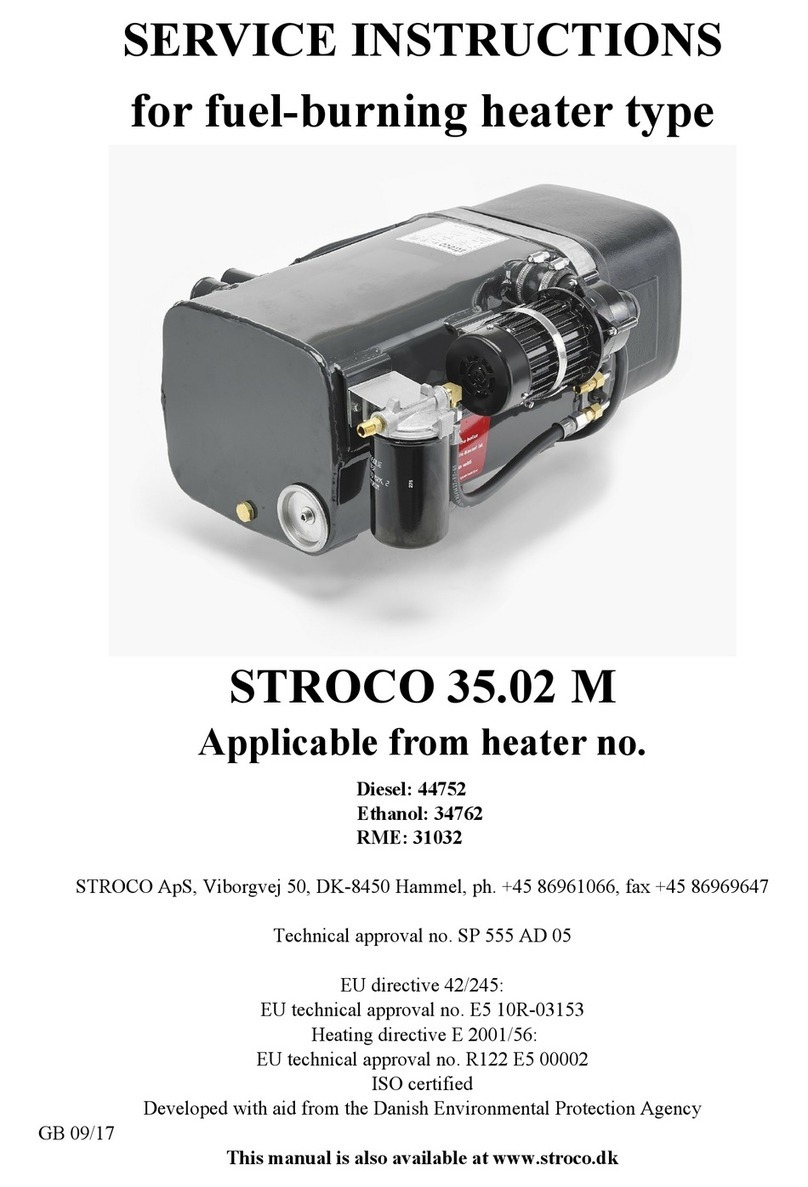
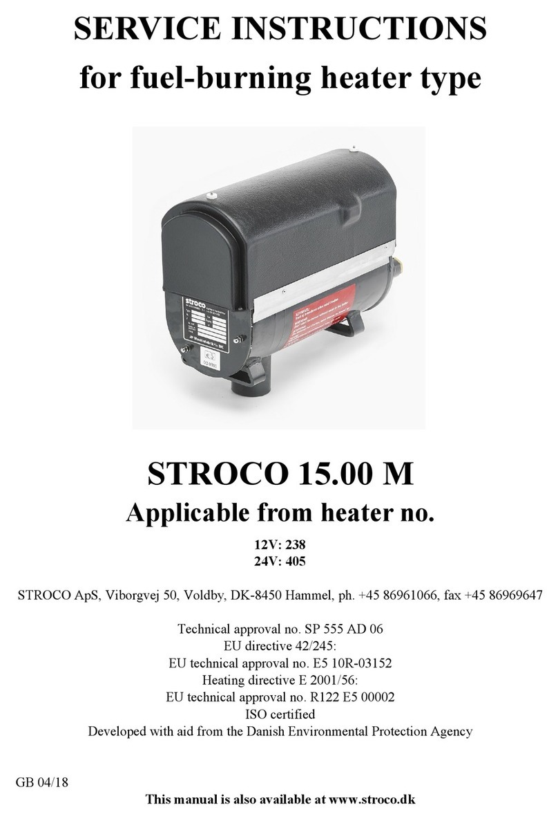
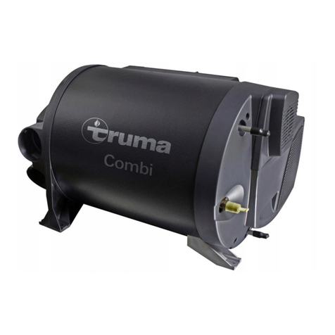
Stroco 672V DC User manual

MANUAL FOR STROCO
PURE
ELECTRIC HEATER
60 kW
STROCO ApS, Energivej 3, DK-6800 Varde, tel. +45 86961066
GB 05/21
This manual is also available at www.stroco.dk

IMPORTANT
PAGE 2
In order to maintain warranty and warranty rights,
the following must at least be met.
1. Installation is performed as described in this manual.
2. Service and repair work must be carried out professionally
correctly.
3. Only original spare parts shall be used.
4. The heater may only be used for the voltage shown on the
type plate.

CONTENTS
PAGE 3
Page:
Description....................................................................................................... 4
Built-in dimentions.......................................................................................... 5
Marking STROCO Electric heater………………………………………… 6
Electrical installation and settings..................................................................7
Coupling scheme........................................................................................... 8-9
Warranty conditions...................................................................................... 10
Dealers.............................................................................................................11

DESCRIPTION
PAGE 4
In order to ensure optimal use of the STROCO Electric heater and ensure maximum safety, it is im-
portant that this manual is read and understood before using the heater.
Please remember to complete warranty card at www.stroco.dk.
The Stroco Electrical heater is used to heat the vehicle during parking and day to day travel on hy-
brid or all-electric vehicles. STROCO Electrical heater is mounted in the vehicle's existing heating
system and can heat the driver's area, passenger space and engine. STROCO Electrical heater has
built-in heating elements operating thermostat and safety thermostat. The type designation 15 kW
indicates the power size of the heating elements in kW. The electrical connection to the electrical ele-
ments is made via a HVDC contactor (not supplied by Stroco) to the heating elements. The HVDC
contactor is controlled via the electrical mechanical contactor inside the connection box which re-
ceives an active 24VDC signal from the vehicle's heat control system to pull the HVDC contactor.
When the temperature is reached, the mechanical contactor breaks the 24 voltage to the HVDC con-
tactor. For circulation of the water, the 24V DC water pump is located on the heater and needs a 10
Amp secured cable connected to the heating control system
Technical specifications
Type: STROCO Electric heater
Heating output EL: 4 x 15 kW
Electrical connection : Terminal block via cable gland
Operating thermostat : Adjustable 37-85°C
Safety thermostat: : 110oC reconnected by push button
Dimensions L x W x H: 420,5 x 365 x 234mm
Weight: 30,2 kg cpl.
Circulation pump : 6000 l/t at 0,4 bar. Power consumption : 6,6A at 24V DC
Operating voltage EL : 672V DC (Max. 10% overvoltage)
MAX. AMBIENT
TEMPERATURE: 80°C
ESSENTIAL! THE HEATING SYSTEM MUST BE FILLED WITH A CORROSION-
RETARDANT ADDITIVE (E.G. 40-60% ANTIFREEZE) .
Heat
Water
Electrical power +=

BUILT-IN DIMENSIONS FOR 4 X 15 kW 672V DC
PAGE 5
Pos. Description Part number
1Heating element 15 kW 672V DC 11.936-1
2VP 6000 L/h 24V DC 7A 0,4 bar 35.470
3Multi 2pole pin plug sleeves 6,3mm 13.561
4Thermostat EGO 37-85°C/110° 11.926
5Terminal Block 11.915
6Boiler Std. (Grey) 35.544
6Boiler (Color RAL 5015 ”Blue”) 35.544-10

MARKING STROCO ELECTRIC HEATER
PAGE 6
Label on connection box

ELECTRICAL INSTALLATION AND SETTING
PAGE 7
The electrical installation is described below and refers to diagrams on the next page.
1 Ground connections
Ground Connections may only be performed, as shown in the diagram on the next page. Ground con-
nections between individual parts must not be conducted outside the armoured hoses. The connec-
ting box connects to the vehicle chassis. The vehicle chassis cleans from paint and rust prevented tho-
roughly. A minimum Ø3.5 mm even cutting or threading screw fitted with a tooth disc may be used.
2 Thermostat
Operating thermostat can be set steplessly from 37°C to 85°C. The thermostat has a built-in hystere
sis of 12 K, i.e. there is 12°C between the connecting and dissconneting. The operating temperature is
set with a screwdriver at . The safety thermostat disconnects if the temperature exceeds 110°C. The
thermostat can be reconnected by pressing the red button.
Note ! The setting and reconnection of thermostats must only be carried out with disconnected
main Switch of the vehicle.
3 Level sensor for low water level of heating circuit.
Level sensor shall be used to block activation of heating elements when water level is low to prevent
damage on the heating elements. (Not supplied by Stroco).

COUPLING SCHEME FOR 4 X 15 kW 672V DC
PAGE 8
15 kW

COUPLING SCHEME FOR 4 X 15 kW 672V DC
PAGE 9
15 kW

WARRANTY CONDITIONS FOR STROCO HEATERS
PAGE 10
STROCO heaters and parts are covered by 24 months warranty. The warranty is valid from the date
of installation, however, no more than 36 months from the date of delivery.
However, the warranty only applies if the guidelines are followed:
The STROCO heater is properly mounted according to manual
Warranty card correctly completed with serial number at www.stroco.dk
The warranty covers manufacturing defects and material defects.
THE WARRANTY LAPSE IF:
Changes that have been made to the system or the system is NOT built in accordance with our
instructions
During the warranty period, STROCO is obligated to repair units or parts that we determine to be
defective. Repairs for complaints must be made in an authorized service workshop or at one of our
partners' workshops.
Labour costs for any complaints on heaters or parts are not covered by STROCO:
If you observe defects in the system during the warranty period, the defective parts should be sent
postage paid to STROCO with information about the defect and delivery date/heater no.
STROCO’s assessment of the defect, and whether it is covered by the warranty, will always be final
and binding for the customer.
STROCO will only accept warranty claims that have been approved beforehand. STROCO can only
accept warranty claims if the owner/user can present written documentation to show that all service
and safety instructions have been followed. All warranties will be void if the installation guide and
other instructions in this manual have not been followed. The same applies if installation and
maintenance has not been performed in a proper professional manner, or if unoriginal parts have
been used for servicing or repairs.
Consequential losses:
STROCO assumes no liability for personal injury, damage to property, or operating losses resulting
from failure of the unit, no matter the cause (including manufacturing defects).

DEALERS
PAGE 11
DANMARK, Denmark:
STROCO ApS Tel. +45 86 96 10 66
Energivej 3 E-mail
DK-6800 Varde [email protected]
ENGLAND:
GRAYSON THERMAL SYSTEMS Tel. +44 121 700 5600
257 Wharfdale Road E-mail
Tyseley [email protected]
GB-Birmingham B11 2DP
FINLAND:
EL-CAR OY Tel. +358 09 389 4995 MUICON OY Tel. +358 44 213 4131
Jukka Eerola E-mail Marko Muikko E-mail
SF-01260 Vantaa SF-70800 Kuopio
FÆRØERNE, the Faroe Islands:
CARE ON SEA Spf Tel. +298 74 88 55
Úti vio Neyst 11 E-mail
FO-430 Hvalvik [email protected]
NORGE, Norway:
VEST SERVICE AS Tel. +47 90 85 60 00
Visnesvegen 9A E-mail
N-6783 Stryn [email protected]
POLEN, Poland:
MULTITECH sp. z o.o. Tel. +48 12 638 06 63
Spcerowa 49 E-mail
PL-32-070 Dabrowa Szlachecka [email protected]
PORTUGAL:
PROJECTIVA Tel. +351 249 819 240
Zona Industrial E-mail
Apartado 175 [email protected]
P-2354-909 Torres Novas
SVERIGE, Sweden:
TK BUSSKLIMAT AB Tel. +46 31 445 200
Järnringen 2 E-mail
S-433 30 Partille [email protected]
ØSTRIG, Austria:
FA. ING. HUBERT KNITTEL Tel. +43 1 804 15 23-0
Lastbergstrasse 41 E-mail
A-3031 Pressbaum [email protected]
Table of contents
Other Stroco Heater manuals
Popular Heater manuals by other brands
Reina
Reina Optima Operation instructions
Zibro
Zibro SRE 150 laser manual
Glen Dimplex
Glen Dimplex zebra OTI-R installation guide
Frico
Frico Thermoplus Instructions for operation

Lochinvar
Lochinvar LBT Series Installation, Commissioning, Maintenance and User instructions
Kampmann
Kampmann Lufterhitzer TOP Series Installation and operating instructions
