Struck SIS3820 User manual

SIS Documentation SIS3820
VME Scaler
Page 1 of 79
SIS3820
VME Scaler
User Manual
SIS GmbH
Harksheider Str. 102A
22399 Hamburg
Germany
Phone: ++49 (0) 40 60 87 305 0
Fax: ++49 (0) 40 60 87 305 20
http://www.struck.de
Version: sis3820-M-0-001-v184-scaler.doc as of 27.07.07

SIS Documentation SIS3820
VME Scaler
Page 2 of 79
Revision Table:
Revision Date Modification
0.0x 13.02.02 Start of module definition
0.10 23.06.03 Prerelease
1.00 24.06.03 First official release
1.01 11.08.03 Id. reg R/W -> R only
bug fix in JTAG JP570 text and watchdog enable
1.10 09.12.03 VME JTAG firmware upgrade support,
read during preset scaler operation, support for 512 MB
memory strips and add mode
(Xilinx Firmware: sis38200102.mcs)
1.20 27.04.04 Firmware Version 01 03
Chained Block Transfer (CBLT) implemented
(Xilinx Firmware: sis38200103.mcs)
1.30 04.06.04 Firmware Version 01 04
48-bit deep counter implementation in channels 1 and 17
(for scaler mode, new address 0x210)
1.31 09.11.04 Bug fix in address map, change FIFO threshold register
explanation
1.32 13.01.05 Couple of index entries added, typo fix
1.40 20.05.05 Firmware Version 01 05
New Control Output mode 2 (10Mhz)
1.50 26.08.05 Firmware Version 01 08
New Control Input mode 6 (with external counter clear)
1.60 14.10.05 Firmware Version 01 09
Bug fix in control input inversion
New register 0x214 (veto external count inhibit)
1.61 20.10.05 Bug fix in example veto external count register
1.70 03.11.05 Firmware Version 01 0A
New register 0x218 (test pulse mask register)
1.71 04.12.05 Bug fixes
1.72 11.02.06 ESD note added
1.80 15.06.06 New MUX_OUT feature, firmware revision 0xB
1.81 19.06.06 Bug fixes
1.82 25.10.06 Note on external LNE/channel N rate being limited to 5
MHz
1.83 21.11.06 JTAG jumper JP570 factory default
1.84 27.07.07 50 ΩTTL and high impedance input configuration

SIS Documentation SIS3820
VME Scaler
Page 3 of 79
1 Table of contents
1 Table of contents ................................................................................................................. 3
2 Introduction ......................................................................................................................... 7
3 Technical Properties/Features.............................................................................................. 8
4 Functionality........................................................................................................................ 9
4.1 Block Diagram ........................................................................................................................................ 9
4.2 Modes of operation ............................................................................................................................... 10
4.2.1 Scaler/Counter............................................................................................................................... 10
4.2.2 Latching Scaler.............................................................................................................................. 10
4.2.3 Preset Scaler.................................................................................................................................. 10
4.2.4 Multi channel Scaler (MCS) ........................................................................................................ 10
4.2.5 Histogramming Scaler(3820 01 02 and higher design) ................................................................. 10
5 Getting started.................................................................................................................... 11
5.1 Installation............................................................................................................................................. 11
5.2 LINUX example/test code..................................................................................................................... 11
5.2.1 User LED test................................................................................................................................ 11
5.2.2 Readout of Module Id. and firmware revision register ................................................................. 11
5.2.3 Standard Counter........................................................................................................................... 12
5.2.4 Multiscaler (MCS) ........................................................................................................................ 13
5.2.5 Preset Scaler.................................................................................................................................. 14
5.3 Win2K/XP Visual C++ example/test code............................................................................................ 15
6 VME Addressing ............................................................................................................... 16
6.1 Address map.......................................................................................................................................... 17
7 Register description ........................................................................................................... 18
7.1 Control/Status Register(0x, write/read)................................................................................................. 19
7.1.1 Counter test mode ......................................................................................................................... 20
7.1.2 25 MHz test pulse mode................................................................................................................ 20
7.1.3 Reference pulser channel 1 ........................................................................................................... 20
7.2 Module Id. and Firmware Revision Register (0x4, read) ...................................................................... 21
7.2.1 Major revision numbers ................................................................................................................ 21
7.3 Interrupt configuration register (0x8).................................................................................................... 22
7.3.1 IRQ mode...................................................................................................................................... 22
7.4 Interrupt Control/Status register (0xC).................................................................................................. 23
7.4.1 Interrupt sources............................................................................................................................ 24
7.5 (0x10)Acquisition preset register .......................................................................................................... 26
7.6 Acquisition count register (0x14).......................................................................................................... 26
7.7 LNE Prescaler factor register (0x18)..................................................................................................... 27
7.8 Preset value register counter group 1 (0x20)......................................................................................... 28
7.9 Preset value register counter group 2 (0x24)......................................................................................... 28
7.10 Preset Enable and Hit register (0x28).................................................................................................... 28
7.11 CBLT/Broadcast setup register ............................................................................................................. 29
7.12 SDRAM page register (0x34) ............................................................................................................... 30
7.13 FIFO word counter/memory address pointer register (0x38) ................................................................ 31
7.14 FIFO word counter threshold (0x3C).................................................................................................... 32
7.15 HISCAL_START_PRESET register (0x40)......................................................................................... 33
7.16 HISCAL_START_COUNTER register (0x44) .................................................................................... 33
7.17 HISCAL_LAST_ACQ_COUNTER register (0x48)............................................................................. 33
7.18 (Acquisition) Operation Mode register (0x100).................................................................................... 34
7.18.1 Modes of Operation modes (Bits 30:28) ....................................................................................... 34
7.18.2 Input modes (Bits 18:16)............................................................................................................... 35
7.18.3 Output mode (Bits 21:20).............................................................................................................. 36
7.18.4 HISCAL_START_SOURCE_BIT (Bit 14) .................................................................................. 36
7.18.5 SDRAM mode (Bit 12) and SDRAM add mode (Bit 13) ............................................................. 37
7.18.6 Arm/enable source ........................................................................................................................ 37
7.18.7 LNE source ................................................................................................................................... 38
7.18.8 Data format ................................................................................................................................... 39

SIS Documentation SIS3820
VME Scaler
Page 4 of 79
7.18.9 Clearing/non clearing .................................................................................................................... 39
7.19 Copy disable register (0x104) ............................................................................................................... 40
7.20 LNE channel select register (0x108) ..................................................................................................... 41
7.21 PRESET channel select register (0x10C).............................................................................................. 42
7.21.1 Preset scheme ................................................................................................................................ 42
7.22 MUX OUT channel select register (0x110) .......................................................................................... 43
7.23 Inhibit/count disable register (0x200) ................................................................................................... 44
7.24 Counter clear register (0x204)............................................................................................................... 44
7.25 Counter Overflow register (0x208) ....................................................................................................... 44
7.26 Channel 1/17 Bits 33-48 register (0x210) ............................................................................................. 45
7.27 Veto external count inhibit register (0x214) ......................................................................................... 45
7.28 Test pulse mask register (0x218) ......................................................................................................... 46
7.29 SDRAM SPD register (0x300).............................................................................................................. 46
7.30 JTAG_TEST register ............................................................................................................................ 47
7.31 JTAG_DATA_IN register..................................................................................................................... 47
7.32 JTAG_CONTROL register ................................................................................................................... 47
7.33 One wire Id. register (tbd)..................................................................................................................... 48
7.34 FIFO address space (0x800000-0xFFFFFC)......................................................................................... 49
7.34.1 non incrementing VME master .....................................................................................................49
7.34.2 incrementing VME master ............................................................................................................ 49
7.35 SDRAM address space (0x800000-0xFFFFFC) ................................................................................... 49
8 Data Format ....................................................................................................................... 50
8.1 32-bit Mode........................................................................................................................................... 50
8.2 24-bit Mode........................................................................................................................................... 50
8.3 16-bit Mode........................................................................................................................................... 51
8.4 8-bit Mode............................................................................................................................................. 51
9 Front panel elements.......................................................................................................... 52
9.1 Front Panel Layout................................................................................................................................ 52
9.2 Front Panel LEDs.................................................................................................................................. 53
9.3 Flat cable Input/Output Pin Assignments.............................................................................................. 54
9.3.1 ECL ............................................................................................................................................... 54
9.3.2 TTL ............................................................................................................................................... 55
10 Board Layout.................................................................................................................. 56
11 Jumper settings/pinouts.................................................................................................. 57
11.1 J1........................................................................................................................................................... 57
11.2 J90......................................................................................................................................................... 57
11.3 JP570 JTAG source............................................................................................................................... 58
11.4 CON500 JTAG ..................................................................................................................................... 58
12 Input Configuration ........................................................................................................ 59
12.1 ECL ....................................................................................................................................................... 59
12.2 LVDS .................................................................................................................................................... 60
12.3 NIM....................................................................................................................................................... 61
12.4 TTL ....................................................................................................................................................... 62
12.4.1 High impedance TTL/LEMO........................................................................................................ 62
12.4.2 50ΩTTL/LEMO........................................................................................................................... 62
12.4.3 TTL/Flat Cable.............................................................................................................................. 62
13 TTL output configuration............................................................................................... 63
14 Signal Specification........................................................................................................ 63
14.1 Control Signals...................................................................................................................................... 63
14.2 Inputs..................................................................................................................................................... 63
14.3 User Bits................................................................................................................................................ 63
15 Theory of operation........................................................................................................ 64
15.1 Enable Logic ......................................................................................................................................... 64
15.2 Read on the fly ...................................................................................................................................... 65
15.3 Latching scaler ...................................................................................................................................... 65
15.4 Preset Scaling........................................................................................................................................ 65
15.5 Multiscaling (MCS) .............................................................................................................................. 66
15.5.1 Minimum dwell time..................................................................................................................... 66

SIS Documentation SIS3820
VME Scaler
Page 5 of 79
15.5.2 arm/enable with MCS.................................................................................................................... 67
15.6 Clearing/non clearing mode .................................................................................................................. 67
15.7 Histogramming Scaler (HISCAL)......................................................................................................... 68
15.7.1 Minimum dwell time in HISCAL mode........................................................................................ 68
15.8 Firmware upgrade over VME ............................................................................................................... 68
15.9 CBLT readout (3820 01 03 and higher design)....................................................................................69
15.9.1 CBLT Setup example.................................................................................................................... 70
15.9.2 CBLT hints.................................................................................................................................... 71
15.10 Broadcast........................................................................................................................................... 71
16 Appendix ........................................................................................................................ 72
16.1 P2 row A/C pin assignments ................................................................................................................. 72
16.2 Row d and z Pin Assignments............................................................................................................... 73
16.3 Connector Types ................................................................................................................................... 74
16.4 Power consumption............................................................................................................................... 74
16.5 Operating conditions ............................................................................................................................. 74
16.5.1 Cooling.......................................................................................................................................... 74
16.5.2 Hot swap/live insertion.................................................................................................................. 74
16.6 LED (selftest)........................................................................................................................................ 74
16.7 VME readout performance.................................................................................................................... 75
16.8 Software Support................................................................................................................................... 75
17 Glossary.......................................................................................................................... 76
18 Index............................................................................................................................... 77

SIS Documentation SIS3820
VME Scaler
Page 6 of 79

SIS Documentation SIS3820
VME Scaler
Page 7 of 79
2 Introduction
The SIS3820 is a multi purpose counter. It combines the functionality of the SIS3800 scaler
and the SIS3801 multiscaler with extended functions. The proven concept of flexible leaded
component based frontend circuitry in conjunction with more recent FPGA (field
programmable gate array) technology results in unprecedented flexibility to implement the
given readout application.
Applications comprise, but are not limited to:
•Nuclear Phyics
•Particle Physics
•Neutrino/Astrophysics
•Synchrotron Radiation
•Neutron Scattering
•Machine (accelerator) diagnosis
•Scanning microscope readout

SIS Documentation SIS3820
VME Scaler
Page 8 of 79
3 Technical Properties/Features
This manual describes the implemented functionality for the SIS3820-SCALER firmware.
Other firmware designs are SIS3820-CLOCK (clock distributor for up to 32 SIS330x VE
digitizers) and SIS3820-LATCH (input register with counter and interrupt functionality)
Find below a list of key features of the SIS3820.
•32 channels (64 channel option)
•4 front panel control inputs
•4 front panel control outputs
•64 Mbytes SDRAM (512 MB option)
•250 MHz counting rate (ECL and NIM), 100 MHz for TTL (50 MHz for P2 fed channels)
•32-bit counter depth (channel 1 and 17 48-bit deep with firmware > 01 04 in scaler mode)
•NIM/TTL/ECL/LVDS versions
•flat cable (ECL, TTL and LVDS) and LEMO (TTL/NIM) options
•multi channel, latching and preset scaler operation
•shadow register (latching scaler mode)
•read on the fly (latching scaler mode)
•reference pulser
•test pulser
•A24/32 D32/BLT32/MBLT64/2eVME/CBLT32)
•Geographical addressing mode (in conjunction with VME64x backplane)
•Broadcast addressing
•Interrupt capabilities
•Hot swap (in conjunction with VME64x backplane)
•VME64x Connectors
•VME64x Side Shielding
•VME64x Front panel
•VME64x extractor handles (on request)
•single supply (+5 V)
•in field firmware upgrade capability
SIS Documentation SIS3820
VME Scaler
Page 9 of 79
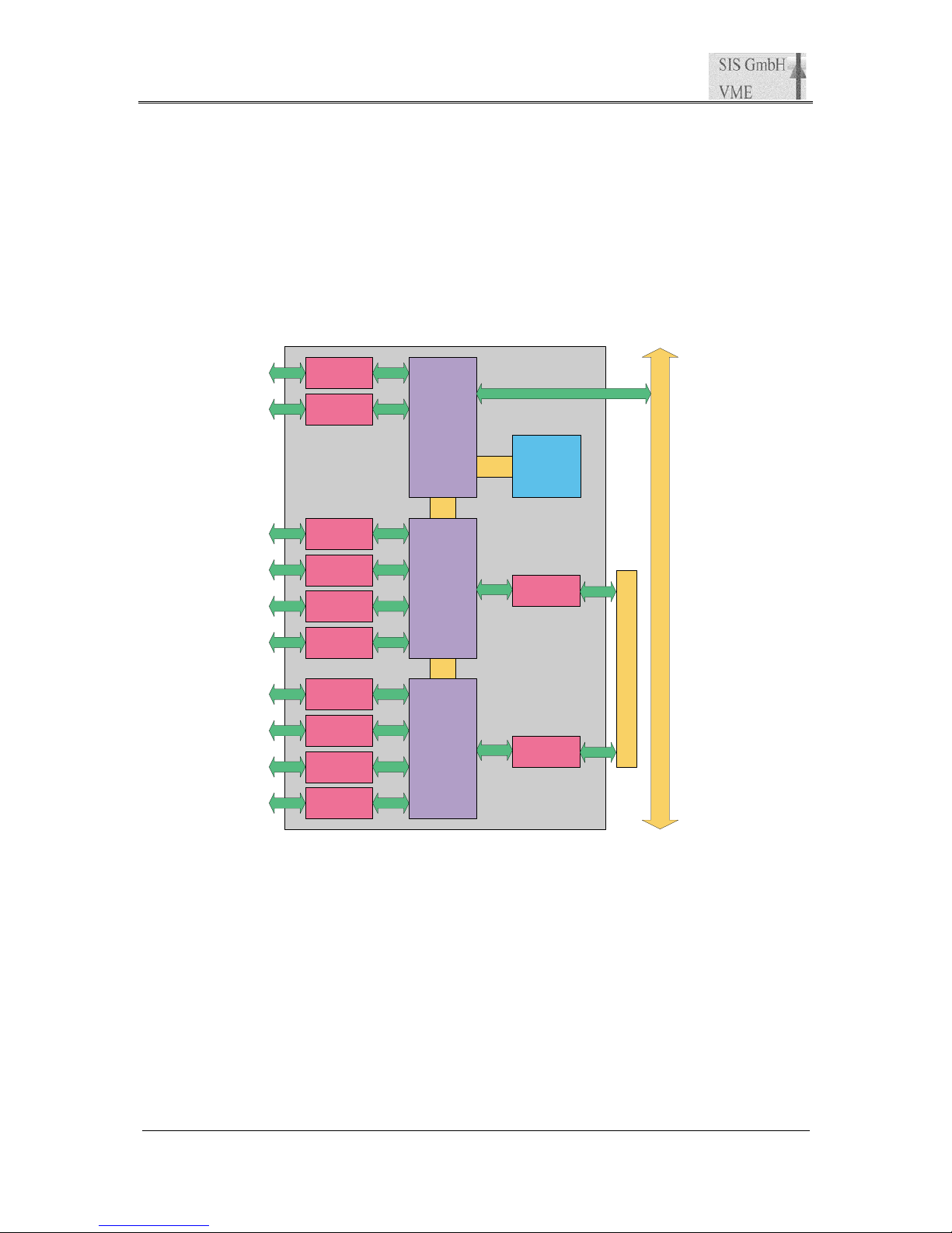
4 Functionality
The functionality of the SIS3820 is a combination of hardware (printed circuit board) design,
stuffing options and firmware. The module consists of two FPGAs that hold the frontend
logic and on FPGA that holds the VME interface, the SDRAM controller and the control logic
functions. Logic level adaptation is handled by classic DIL components and single inline
(SIL) resistor networks. The firmware is loaded from a serial PROM at power up. Both JTAG
and VME can be used for in field firmware upgrades/changes.
4.1 Block Diagram
SDRAM
4 x Level Adaptation
Driver/Receiver
4 x Level Adaptation
Driver/Receiver
4 x Level Adaptation
Driver/Receiver
4 x Level Adaptation
Driver/Receiver
Driver/Receiver 16 x
Frontend
FPGA
4 x Level Adaptation
Driver/Receiver
4 x Level Adaptation
Driver/Receiver
4 x Level Adaptation
Driver/Receiver
4 x Level Adaptation
Driver/Receiver
Driver/Receiver 16 x
VME
and
Control
FPGA
4 x Level Adaptation
Driver/Receiver
4 x Level Adaptation
Driver/Receiver
Frontend
FPGA
P2 (A,C)
VME P1 and P2

SIS Documentation SIS3820
VME Scaler
Page 10 of 79
4.2 Modes of operation
4.2.1 Scaler/Counter
In standard counter/scaler mode data can be read on the fly with an accuracy to the least
significant bit. No counts are lost in read on the fly mode.
4.2.2 Latching Scaler
In latching scaler mode scaler values are copied to a shadow register set upon a front panel
signal LNE or a VME command. Broadcast functionality is implemented for the later to allow
for minimum time difference over a set of several SIS3820s without front panel cabling.
4.2.3 Preset Scaler
The SIS3820 can be operated as preset scaler. An arbitrary channel or a combination of
channels can be selected as the condition for the termination of the counting process. The
selection of the channel(s) is done via the preset enable mask register . The first selected
channel that reaches its preset value will terminate the counting process. The actual preset
values are defined though the preset value register set. The internal 25 MHz pulse generator
(or a prescaled derived output) can be used as time base for measurements if its enabled for
channel 1 with this channel being enabled in the preset enable mask and the desired prescale
factor stored into the channel 1 preset value register. The terminating channel can be
identified by the actual scaler data or the preset hit mask register if more than one preset
channel is enabled.
4.2.4 Multi channel Scaler (MCS)
MCS mode allows for the buffered readout of variable or fixed lengths counting time
intervals. The interval length can be defined by an internal timer as well as by an external
signal, which can be prescaled also. The minimum buffer memory size of 64 MB takes the
realtime burden away from the VME master even at very short time intervals (dwell times).
Two factors facilitate short dwell time applications. The first is high speed VME readout of
data from SDRAM in MBLT64 and 2eVME. The second is data compression with a
reduction in counter depth to 16 or 8-bit. Data compression is also a good way to save VME
bandwidth in lower count rate applications (with V/F converters e.g.) at longer dwell times.
4.2.5 Histogramming Scaler(3820 01 02 and higher design)
Histogramming scaler mode (MCS mode with add enabled) allows to acquire and add MCS
data of several repeated scans in SDRAM without CPU interaction. The user has to make
sure, that the reset to the first bin and the number of bins are issued with the accuracy that is
required by the application. I.e. no number of bin/reset checking mechanism is implemented
(unlike in the SIS3100-HISCAL DSP based design).

SIS Documentation SIS3820
VME Scaler
Page 11 of 79
5 Getting started
This section is intended for the first time SIS3820 user. In some cases it may be good enough
to use the provided header file and C examples to get acquainted to a couple of the modules
functions before looking at the other sections of the manual in more detail. If you have a
SIS1100/3100 PCI to VME interface under LINUX or under Win2K/XP with Visual C++ you
can use the provided example code without modifications.
5.1 Installation
•Select addressing A32 or geographical address mode with J1 (factory default is A32)
•Select base address with SW3 and SW4 in non geographical addressing (the default base
address setting is 0x38000000)
•turn VME crate power off
•install your SIS3820 board in the VME crate
•connect inputs
•turn VME crate power back on
•verify, that the P (power) and R (ready) LEDs are on and all other LEDs are off after the
approximately 2s long power up self test cycle
5.2 LINUX example/test code
The file sis3820.tar.gz holds LINUX example programs, the sis3820.h header files and
Makefiles to generate the executables.
Initial VME access test
Both the user LED and readout of the Module Id. and firmware register provide a good way to
verify that proper initial communciation with the SIS3820 can be established.
5.2.1 User LED test
The program sis3820_led.c runs 30 cycles with the sequence user LED on, sleep(1), user LED
off, sleep(1).
5.2.2 Readout of Module Id. and firmware revision register
The program sis3820_readmodid.c reads and displays the module identification and firmware
register.
mki@mki:~/sis1100/sis3820> ./sis3820_readmodid
Module identification and firmware register reads: 38200102

SIS Documentation SIS3820
VME Scaler
Page 12 of 79
5.2.3 Standard Counter
In the minimum counter application you enable the logic, have the module count for a period
of time and read out the scaler values after disabling the logic.
The sis3820_counter program runs 2 counting cycles of 5 s each. During the second cycle the
internal 50 MHz reference pulse generator is routed to channel 1. Sample output with a 11
MHz signal connected to scaler channel 17 is shown below.
mki@mki:~/sis1100/sis3820> ./sis3820_counter
SIS3820 scaler counting
gotwords 32
scaler data
ch01 00000000 ch02 00000000 ch03 00000000 ch04 00000000
ch05 00000000 ch06 00000000 ch07 00000000 ch08 00000000
ch09 00000000 ch10 00000000 ch11 00000000 ch12 00000000
ch13 00000000 ch14 00000000 ch15 00000000 ch16 00000000
ch17 03477ce7 ch18 00000000 ch19 00000000 ch20 00000000
ch21 00000000 ch22 00000000 ch23 00000000 ch24 00000000
ch25 00000000 ch26 00000000 ch27 00000000 ch28 00000000
ch29 00000000 ch30 00000000 ch31 00000000 ch32 00000000
now with reference pulser on ch1 enabled
SIS3820 scaler counting
gotwords 32
scaler data
ch01 0eedfb33 ch02 00000000 ch03 00000000 ch04 00000000
ch05 00000000 ch06 00000000 ch07 00000000 ch08 00000000
ch09 00000000 ch10 00000000 ch11 00000000 ch12 00000000
ch13 00000000 ch14 00000000 ch15 00000000 ch16 00000000
ch17 0348d70d ch18 00000000 ch19 00000000 ch20 00000000
ch21 00000000 ch22 00000000 ch23 00000000 ch24 00000000
ch25 00000000 ch26 00000000 ch27 00000000 ch28 00000000
ch29 00000000 ch30 00000000 ch31 00000000 ch32 00000000
Note: The 50 MHz reference pulse generator will give you an idea on the sleep/scheduling
accuracy of your LINUX system.

SIS Documentation SIS3820
VME Scaler
Page 13 of 79
5.2.4 Multiscaler (MCS)
MCS mode is demonstrated with the program sis3820_mcs.c. With respect to the fact that
SDRAM mode with a fixed number of acquisitions is used, its kind of a minimum approach
that does not make use of the full capabilities of the SIS3820.
The example uses the internal 10 MHz LNE source, which is run through the LNE prescaler
to minimize the need for external signals. The number of acquisitions is preset with the
acquisition preset register. The acquisition count register is used to determine completion of
the acquisition process.
Find below the output of the program for 11 LNEs (corresponding to 11 time slices) with an
input rate of 11 MHz moved across scaler channel 1 to channel 4 as the MCS acquisition is
going on. Note that the CLR LED is pulsed with every LNE and that the S LED is on from
the enable command until the acquisition preset has been reached.
mki@mki:~/sis1100/sis3820> ./sis3820_mcs
MCS mode, scan 1 completed
MCS mode, scan 2 completed
MCS mode, scan 3 completed
MCS mode, scan 4 completed
MCS mode, scan 5 completed
MCS mode, scan 6 completed
MCS mode, scan 7 completed
MCS mode, scan 8 completed
MCS mode, scan 9 completed
MCS mode, scan 10 completed
gotwords 40
scaler data
scan: 001 ch01 00a7d8f7 ch02 00000000 ch03 00000000 ch04 00000000
scan: 002 ch01 00a7d8f7 ch02 00000000 ch03 00000000 ch04 00000000
scan: 003 ch01 008f5010 ch02 00000000 ch03 00000000 ch04 00000000
scan: 004 ch01 00000000 ch02 003d3c9f ch03 00000000 ch04 00000000
scan: 005 ch01 00000000 ch02 00a7d8f7 ch03 00000000 ch04 00000000
scan: 006 ch01 00000000 ch02 002255a6 ch03 00000000 ch04 00000000
scan: 007 ch01 00000000 ch02 00000000 ch03 006ee942 ch04 00000000
scan: 008 ch01 00000000 ch02 00000000 ch03 0076e9f4 ch04 00000000
scan: 009 ch01 00000000 ch02 00000000 ch03 00000000 ch04 00438a6e
scan: 010 ch01 00000000 ch02 00000000 ch03 00000000 ch04 00a7d8f7

SIS Documentation SIS3820
VME Scaler
Page 14 of 79
5.2.5 Preset Scaler
The sis3820_preset example illustrates preset scaling. Counter group 1 is activated for preset
scaling with channel 4 selected as preset channel (channel 1 with the TESTMKI compiler flag
set). A value of 0x1000000 is written to the preset value register of counter group 1 and the
logic enabled afterwards. The status of the preset enable and hit register is polled until
channel group 1 has reached its preset value..
mki@mki:~/sis1100/sis3820> ./sis3820_preset
gotwords 32
scaler data
ch01 00000000 ch02 00000000 ch03 00000000 ch04 01000002
ch05 00000000 ch06 00000000 ch07 00000000 ch08 00000000
ch09 00000000 ch10 00000000 ch11 00000000 ch12 00000000
ch13 00000000 ch14 00000000 ch15 00000000 ch16 00000000
ch17 00000000 ch18 00000000 ch19 00000000 ch20 00000000
ch21 00000000 ch22 00000000 ch23 00000000 ch24 00000000
ch25 00000000 ch26 00000000 ch27 00000000 ch28 00000000
ch29 00000000 ch30 00000000 ch31 00000000 ch32 00000000
mki@mki:~/sis1100/sis3820>
Note 1: It will take in the order of 100 ns after the preset condition was detected before the
counter will stop counting. This implies, that the actual stored counter value will be greater
than the preset value for frequencies in excess of some 10 MHz. Above output was generated
with a symmetric 15 MHz source e.g.
Note 2: The current version of the sis3820_preset features readout in 1s intervals in
parallel to ongoing acquisition.

SIS Documentation SIS3820
VME Scaler
Page 15 of 79
5.3 Win2K/XP Visual C++ example/test code
Find below a screen shot of the Visual C++ directory of the SIS36/38xx CDROM. A short
description is given in the header section of the individual C files.
SIS Documentation SIS3820
VME Scaler
Page 16 of 79
6 VME Addressing
As the SIS3820 features memory options with up 512 Mbytes of SDRAM, A32 addressing
was implemented as the only option. Hence the module occupies an address space of
0xFFFFFF Bytes (i.e. 16 MBytes).
The SIS3820 firmware addressing concept is a pragmatic approach to combine standard
rotary switch style settings with the use of VME64x backplane geographical addressing
functionality.
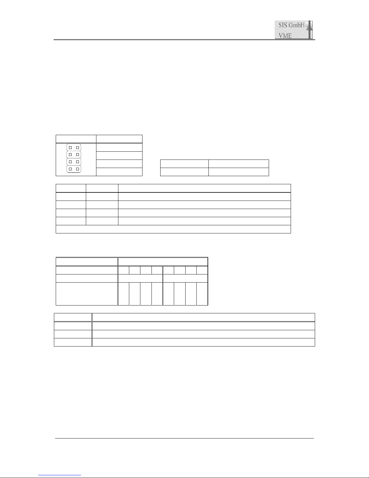
The base address is defined by the selected addressing mode, which is defined by jumper
array J1 and possibly SW4 and SW3 (in non geographical mode).
Function
EN_A32
reserved
EN_GEO SDRAM_SIZE open: 64 MByes
J1
SDRAM_SIZE closed: 512 MBytes
EN_A32 EN_GEO Description
0 0 non A32 addressing, reserved for future use
0 1 non A32 addressing, reserved for future use
1 0 A32 addressing, address compared with SW3/SW4
1 1 A32 addressing, address compared with geographical address
0: jumper open, 1: jumper closed
The table below illustrates the possible base address settings.
J1 Setting Bits
GEO 31 30 29 28 27 26 25 24
- SW4 SW3
x
y
y
y
GA4
GA3
GA2
GA1
GA0
Shorthand Explanation
SW3/SW4 Setting of rotary switch SW3 or SW4 respective
y don’t care
GA0-GA4 Geographical address bit as defined by the VME64x(P) backplane
Notes:
•This concept allows the use of the SIS3820 in standard VME as well as in VME64x
environments, i.e. the user does not have to use a VME64x backplane.
•The factory default setting is 0x38000000 (i.e. SW4=3, SW3=8, EN_A32 closed and
EN_GEO open/disabled)
SIS Documentation SIS3820
VME Scaler
Page 17 of 79
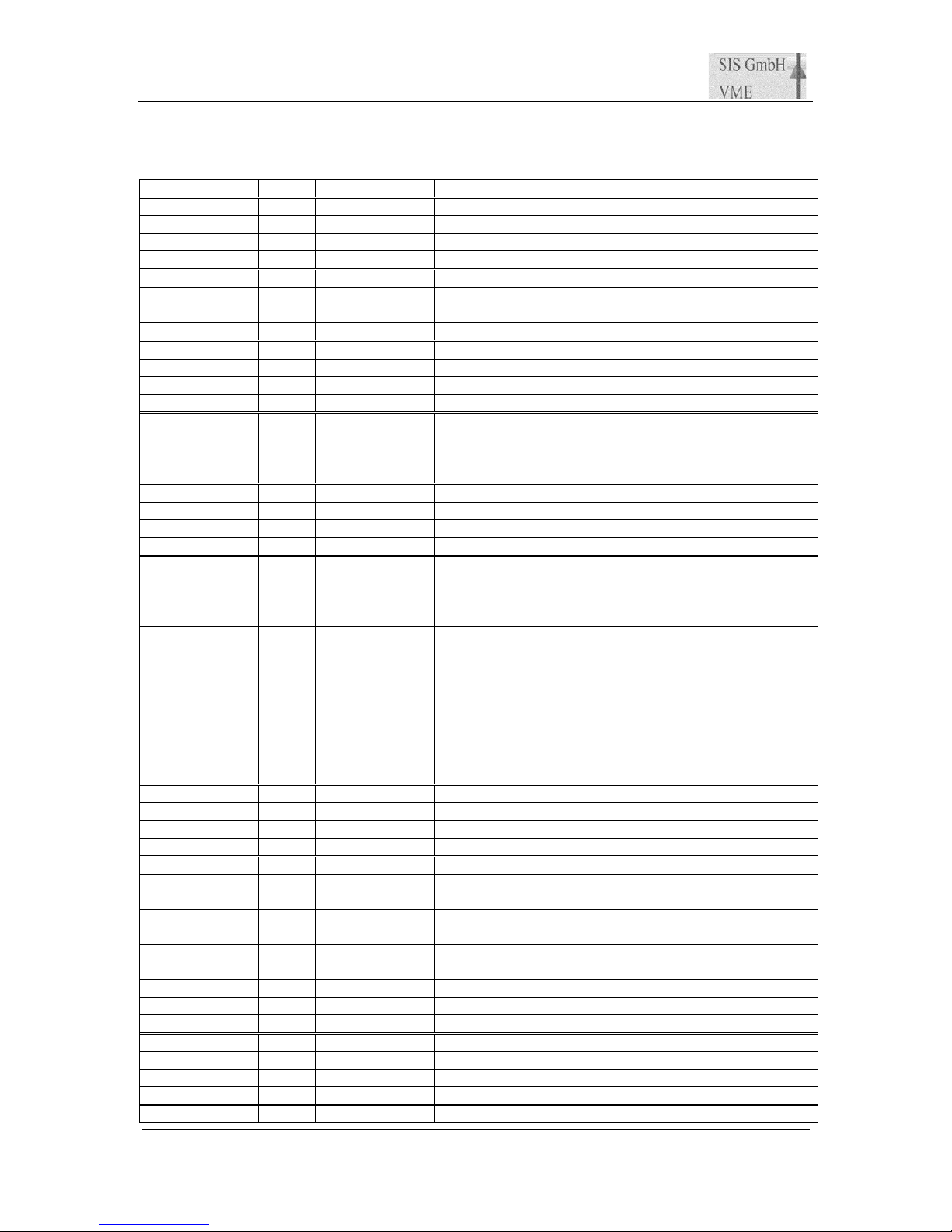
6.1 Address map
Offset R/W Mode Function/Register
0x0 R/W D32 Control/Status register
0x4 R D32 Module Id. and firmware revision register
0x8 R/W D32 Interrupt configuration register
0xC R/W D32 Interrupt control/status register
0x10 R/W D32 Acquisition preset register
0x14 R D32 Acquisition count register
0x18 R/W D32 LNE prescale factor register
0x20 R/W D32 Preset value register counter group 1 (1 to 16)
0x24 R/W D32 Preset value register counter group 2 (17 to 32)
0x28 R/W D32 Preset enable and hit register
0x30 R/W D32 CBLT/Broadcast setup register
0x34 R/W D32 SDRAM page register
0x38 R D32 FIFO Word count register
0x3C R/W D32 FIFO Word count threshold register
0x40 R/W D32 HISCAL_START_PRESET
0x44 R D32 HISCAL_START_COUNTER
0x48 R D32 HISCAL_LAST_ACQ_COUNTER
0x100 R/W D32 (Acquisition) Operation mode register
0x104 R/W D32 Copy disable register
0x108 R/W D32 LNE channel select register (1 of 32)
0x10C R/W D32 PRESET channel select register ( 2 times 1 out of 16)
0x110 R/W D32 MUX_OUT channel select register (firmware 01 0B, 1 of 32,
note 2)
0x200 R/W D32 Inhibit/count disable register
0x204 W D32 Counter Clear register
0x208 R/W D32 Counter Overflow read and clear register
0x210 R D32 Channel 1/17 Bits 33-48
0x214 R/W D32 Veto external count inhibit register (firmware 01 09, note 2)
0x218 R/W D32 Test pulse mask register (firmware 01 0A, note 2)
0x300 R/W SDRAM Prom
0x310 R/W XILINX JTAG_TEST/JTAG_DATA_IN
0x314 W XILINX JTAG_CONTROL
future use R/W One wire Id. register
0x400 KA D32 (broadcast) Key reset
0x404 KA D32 (broadcast) Key SDRAM/FIFO reset
0x408 KA D32 (broadcast) Key test pulse
0x40C KA D32 (broadcast) Key Counter Clr
0x410 KA D32 (broadcast) Key VME LNE/clock shadow
0x414 KA D32 (broadcast) Key operation arm
0x418 KA D32 (broadcast) Key operation enable
0x41C KA D32 (broadcast) Key operation disable
0x420 KA D32
0x424 KA D32
0x428 KA D32
0x42C KA D32

SIS Documentation SIS3820
VME Scaler
Page 18 of 79
0x800 to 0x87C R D32/BLT32 Shadow registers
0xA00 to 0xA7C R D32/BLT32 Counter registers
0x800000 to
0xfffffc
W
R
D32/BLT32
D32/BLT32/
MBLT64/2eVme
SDRAM or FIFO space array
(address window for page of 8 Mbytes)
Notes:
1.) SDRAM (FIFO respective ) write access with active MCS mode will result in a VME
bus error. In MCS mode the memory is reserved for storage of the counter values.
2.) firmware 01 0A indicates revision 01 0A and higher unless otherwise
The shorthand KA stands for key address. Write access with arbitrary data to a key address
initiates the specified function
7 Register description
The function of the individual registers is described in detail in this section.
The first line after the subsection header (in Courier font) like:
#define SIS3820_CONTROL_STATUS 0x0 /* read/write; D32 */
refers to the sis3820.h header file.
SIS Documentation SIS3820
VME Scaler
Page 19 of 79
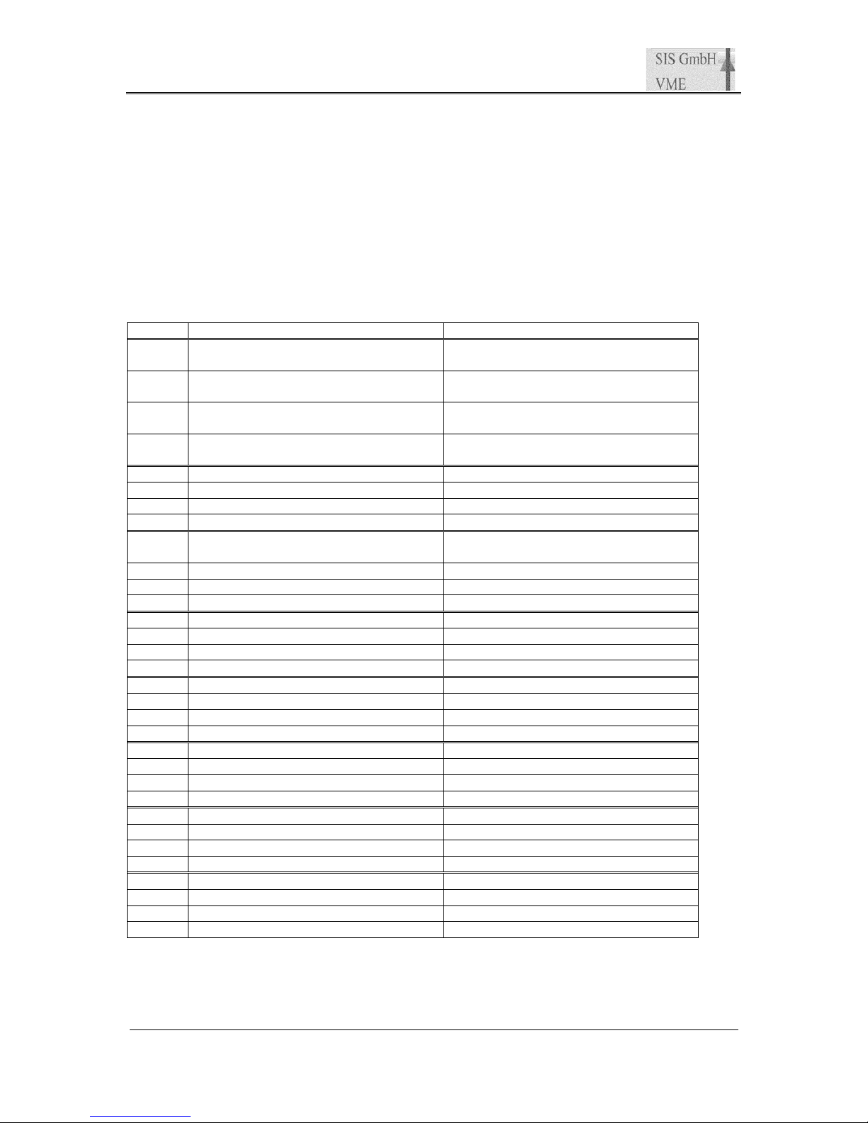
7.1 Control/Status Register(0x, write/read)
#define SIS3820_CONTROL_STATUS 0x0 /* read/write; D32 */
The control register is in charge of the control of some basic properties of the SIS3820 board,
like enabling test pulse generators. It is implemented via a selective J/K register, a specific
function is enabled by writing a 1 into the set/enable bit, the function is disabled by writing a
1 into the clear/disable bit (which location is 16-bit higher in the register). An undefined
toggle status will result from setting both the enable and disable bits for a specific function at
the same time.
On read access the same register represents the status register.
Bit write Function read Function
31 Status external LATCH Bit2 (depending on
Input Mode)
30 Status external LATCH Bit1 (depending on
Input Mode)
29 Status external Input Bit2 (depending on
Input Mode)
28 Status external Input Bit1 (depending on
Input Mode)
27 Overflow
26 0
25 Status HISCAL operation enable
24 Status Operation armed
23 Status Operation SDRAM/FIFO Test
enabled
22 switch off reference pulser channel 1 (*) 0
21 counter test mode (*) 0
20 clear 25MHz test pulses (*) 0
19 0
18 Status Operation MCS enable (active)
17 0
16 switch off user LED (*) Status Operation Scaler enable (active)
15 0
14 0
13 0
12 0
11 0
10 0
9 0
8 0
7 0
6 switch on 50 MHz reference pulser channel 1 Status reference pulser
5 enable counter test mode Status counter test mode enable
4 enable 25MHz test pulses Status 25MHz test pulses
3 0
2 0
1 0
0 switch on user LED Status User LED (1=LED on, 0=LED off)
(*) denotes power up default setting, i.e. the power up reading of the register is 0x0

SIS Documentation SIS3820
VME Scaler
Page 20 of 79
7.1.1 Counter test mode
VME Key test pulse signals will be counted by all (non inhibited) counters in test mode.
Counter test mode has to be activated for 25 MHz test pulse operation also.
7.1.2 25 MHz test pulse mode
All (non inhibited) scaler channels will count 25 MHz test pulses if this bit and the counter
test mode bit is set. From firmware 01 0A on you can use the test pulse mask register to
exclude selected channels from participating in test pulse counting.
7.1.3 Reference pulser channel 1
Channel 1 will count 50 MHz reference pulses (precision defined by the on board 100 ppm 50
MHz quarz) if this bit is set.
Note: test mode has priority over reference pulser, i.e. reference pulses will not be counted if
test mode (with or without 25 MHz test pulse mode) is active.
Table of contents
Other Struck Media Converter manuals

Popular Media Converter manuals by other brands


Crestron
Crestron HD-PS401 quick start

ADS Technologies
ADS Technologies PVC-561 quick guide

Lenz
Lenz Digital plus LR101 Information

Motrona
Motrona SI 251 operating instructions

Lindy
Lindy 43281 user manual

Intelligent Motion Systems
Intelligent Motion Systems RS-232 to RS-422 Converter CV-3222 operating instructions


