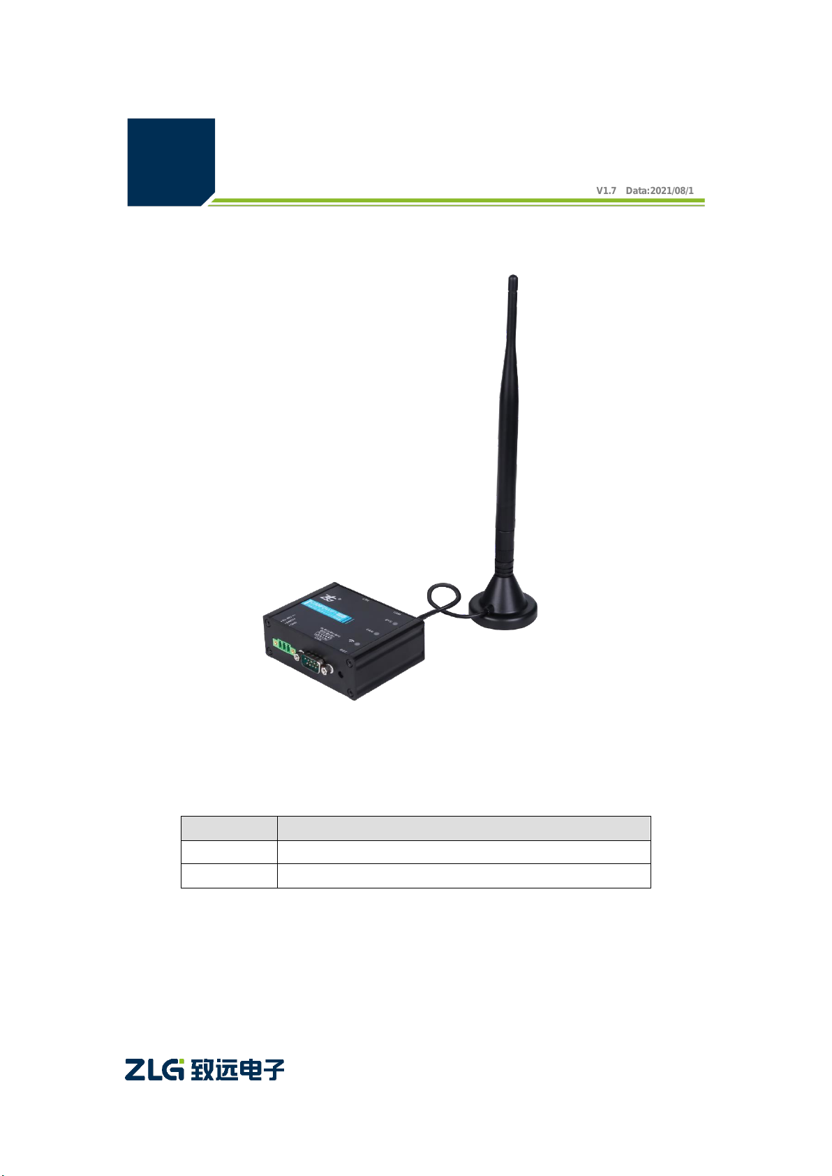
ZLG CANFDWIFI-100U User manual

Category
Contents
Keywords
CAN(FD)-BUS forwarding WIFI
Description
Product User Guide
CANFDWIFI-100U User Manual
V1.7 Data:2021/08/13
Single-Channel CAN(FD) to WIFI Converter
©2021 Guangzhou ZLG Microelectronics Technology Corp.,Ltd.

CANFDWIFI-100U
Single-channel CAN (FD) to WIFI converter
©2021 Guangzhou ZLG Microelectronics Technology Corp.,Ltd.
2
User Manual
Revision History
Version
Date
Reason
V1.0
March 30, 2019
Created
V1.1
May 20, 2020
1. Updated the hardware description of the product;
2. Added configuration parameters such as "Controller Type"
and "Error Notification Port";
3. Supported the WIFI 5G channel;
V1.2
June 3, 2020
1. Modified the parameter name of "Controller Type" and the
corresponding option name;
2. Added the introduction to the CANWIFI-200T protocol
format in the appendix;
V1.3
June 18, 2020
1. Added the size limit description of WIFI name and
password;
V1.4
June 28, 2020
Modified the description of the firmware upgrade;
V1.5
July 1, 2020
Added description of the multicast function;
V1.6
September 29, 2020
Updated the mechanical dimension drawing
V1.7
August 12, 2021
1. Updated the configuration description
2. Updated the CAN indicator description

CANFDWIFI-100U
Single-channel CAN (FD) to WIFI converter
©2021 Guangzhou ZLG Microelectronics Technology Corp.,Ltd.
1
User Manual
Contents
1. Product Introduction.....................................................................................1
1.1 Product Overview...........................................................................................1
1.2 Product Features ...........................................................................................2
1.2.1 Hardware Parameters ............................................................................2
1.2.2 Functional Parameters ...........................................................................2
2. Product Specifications .................................................................................4
2.1 WLAN.............................................................................................................4
2.2 LAN ................................................................................................................4
2.3 CAN (FD) .......................................................................................................4
2.4 Electrical Parameters.....................................................................................4
2.5 Operating Temperature..................................................................................4
2.6 Protection class..............................................................................................4
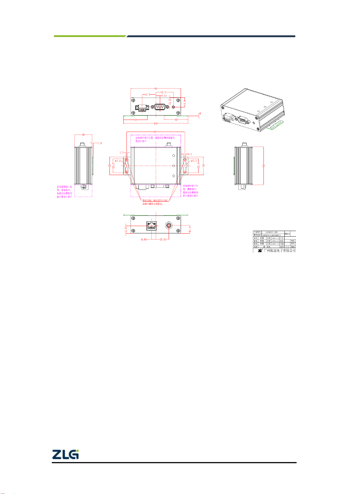
3. Mechanical Installation Dimensions.............................................................6
4. Hardware Interfaces.....................................................................................7
4.1 Panel Layout..................................................................................................7
4.2 Indicators........................................................................................................7
4.3 Button.............................................................................................................8
4.4 Power Interface..............................................................................................8
4.5 CAN(FD) Communication Interface...............................................................8
4.6 Ethernet Interface ..........................................................................................9
4.7 CAN Bus Connection.....................................................................................9
5. Quick Instructions ......................................................................................11
5.1 Hardware Connection..................................................................................11
5.2 Software Installation.....................................................................................12
5.3 Configuring the Device.................................................................................12
5.3.1 Running the Configuration Tool............................................................12
5.3.2 Searching for Devices ..........................................................................13
5.3.3 Configuring Parameters........................................................................14
5.4 CANFDWIFI-100U Communicating with the USBCANFD-200U ................17
5.5 Wireless Connection Mode..........................................................................25
5.5.1 AP Hotspot Mode..................................................................................25
5.5.2 Station Client Mode ..............................................................................26
5.6 Working Mode..............................................................................................27
5.6.1 TCP Server Mode.................................................................................28
5.6.2 TCP Client Mode ..................................................................................29
5.6.3 UDP Mode ............................................................................................30
6. Other Function Description ........................................................................32
6.1 Device Reset................................................................................................32
6.2 Restoring Factory Settings ..........................................................................32
6.3 Device Upgrade...........................................................................................32

CANFDWIFI-100U
Single-channel CAN (FD) to WIFI converter
©2021 Guangzhou ZLG Microelectronics Technology Corp.,Ltd.
2
User Manual
6.4 Device Logs .................................................................................................33
7. Appendix....................................................................................................34
7.1 Configuring Parameters...............................................................................34
7.2 CANFDWIFI-100U Network Data Format....................................................41
7.3 1002100310071009.....................................................................................46
8. Disclaimer..................................................................................................48

CANFDWIFI-100U
Single-channel CAN (FD) to WIFI converter
©2021 Guangzhou ZLG Microelectronics Technology Corp.,Ltd.
1
User Manual
1. Product Introduction
1.1 Product Overview
CANFDWIFI-100U is a high-performance WIFI and CAN(FD)-bus data conversion
equipment developed by Guangzhou ZLG Electronics Co., Ltd. It integrates one
CAN(FD)-bus interface, one Ethernet interface and 1 WiFi interface, and provides a
mature and stable TCP/IP protocol stack. Users can easily complete the interconnection
between CAN-bus network and WiFi network, and further expand the scope of CAN-bus
network.
CANFDWIFI-100U has 2.4G, 5G WLAN interfaces, compliant with IEEE
802.11a/b/g/n/ac standard. It has one 10M/100M adaptive Ethernet interface and one
CAN (FD) port with a maximum baud rate of 5 Mbps. It supports TCP Server, TCP Client,
UDP and other working modes. Through the configuration software, users can flexibly set
configuration parameters. Figure 1.1 shows a typical application.
Figure 1.1 CANFDWIFI typical application

CANFDWIFI-100U
Single-channel CAN (FD) to WIFI converter
©2021 Guangzhou ZLG Microelectronics Technology Corp.,Ltd.
2
User Manual
1.2 Product Features
1.2.1 Hardware Parameters
528 MHz main frequency M7 core processor;
10M/100M self-applicable Ethernet interface, 2 kV electromagnetic isolation;
Integrates 2.4G, 5G WLAN interfaces, and complies with IEEE 802.11a/b/g/n/ac
Embedded hardware watchdog;
Rated power supply voltage of 9-48 V DC, with the anti-reverse connection
function;
Operating power: less than 2 W;
Operating temperature: -20℃to +75℃;
Humidity: 5%-95% RH, no condensation;
1.2.2 Functional Parameters
CAN(FD) interface function supported:
Support baud rate 40K-5Mbps, baud rate can be set arbitrarily;
Support various controller types: CAN, CANFD ISO or CANFD Non-ISO;
Support software to set the CAN (FD) channel 120 ohm terminal resistance
switch;
Support message filtering;
The message sending buffer can be set, and the user can choose the most
suitable balance between real-time and large-capacity buffering;
Multiple working modes supported:
Working modes: TCP Server, TCP Client, UDP;
Support static or dynamic IP acquisition;
Operating port, and destination IP address and target port can be set;
Supports two TCP servers, each of each supports a maximum of 16
connections; or supports a maximum of 16 TCP Client or UDP connections;
In each mode, you can choose to upload the CAN (FD) channel message
and error message, which can be flexibly used in various scenarios;
The TCP Server/Client mode connection has a built-in TCP keep-alive
mechanism to ensure reliable TCP connections;
In TCP Client mode, the network will automatically reconnect after
disconnection, and the TCP connection will be established reliably;
In UDP mode, multicast operation is supported for multiple users to control
multiple CAN (FD) channels at the same time;
Supported TCP/IP protocols include IP,ARP, ICMP, UDP, DHCP, DNS, TCP;
Flexible CAN (FD) packet settings meet various packet requirements of
users;
The communication protocol is open, and the secondary development

CANFDWIFI-100U
Single-channel CAN (FD) to WIFI converter
©2021 Guangzhou ZLG Microelectronics Technology Corp.,Ltd.
3
User Manual
interface function library is provided (Windows and Linux platforms
supported);
You can configure the working parameters by using the configuration tool, and
provide the secondary development interface function library (Windows, Linux
platforms supported);
Support local system firmware upgrade.
Support the device to connect to the ZWS cloud server, and can remotely
upgrade the device, configure the device, and send and receive CANFD
messages from the device.

CANFDWIFI-100U
Single-channel CAN (FD) to WIFI converter
©2021 Guangzhou ZLG Microelectronics Technology Corp.,Ltd.
4
User Manual
2. Product Specifications
2.1 WLAN
Integrate 2.4G, 5G WLAN interface, comply with IEEE 802.11a/b/g/n/ac standard,
and supportAP and Station mode.
2.2 LAN
10M/100M Ethernet, RJ45 interface, 2 kV electromagnetic isolation.
2.3 CAN (FD)
Number of CAN (FD) ports: 1
Interface type: DB9 terminal
Signal cable: CANH, CANL
Baud rate: 40 kbps - 5 Mbps
2.4 Electrical Parameters
Table 1 Electrical parameters
Parameter Name
Conditions
Rating
Unit
Minimum
Typical value
Maximum
Operating voltage
DC
9
12
48
V
Power consumption
-
1.5
-
W
2.5 Operating Temperature
Table 2.2 Operating temperature
Parameter Name
Rating
Unit
Minimum
Typical
Value
Maximum
Operating
temperature
-20
-
75
℃
Storage
Temperature
-40
-
85
℃
2.6 Protection class
Table 2.3 Protection level-electrostatic discharge immunity test (IEC61000-4-2)
Interface
Test Level
Test Voltage (kV)
Remarks
Power supply
Class B
±4
Contact
discharge
CAN bus
Class B
±4
Contact
discharge
WIFI
Class B
±4
Contact
discharge

CANFDWIFI-100U
Single-channel CAN (FD) to WIFI converter
©2021 Guangzhou ZLG Microelectronics Technology Corp.,Ltd.
5
User Manual
Ethernet
Class B
±4
Contact
discharge
Buttons, Indicators
Class B
±8
Air discharge
Table 2.4 Protection level-electrical fast transient pulse group immunity test (IEC61000-4-4)
Interface
Test Level
Test Voltage (kV)
Remarks
Power supply
Class B
±1
Capacitive
coupling
CAN bus
Class B
±1
Capacitive
coupling
Ethernet
Class B
±1
Capacitive
coupling
Table 2.5 Protection level-surge (impact) test (IEC61000-4-5)
Interface
Test Level
Test Voltage (kV)
Remarks
Power supply
Class B
±1
Line-line
Class B
±1
Line-ground
CAN bus
Class B
±1
Line-line
Class B
±1
Line-ground
Ethernet
Class B
±1
Line-line
Class B
±1
Line-ground
WIFI
Class B
±1
Line-line
Class B
±1
Line-ground

CANFDWIFI-100U
Single-channel CAN (FD) to WIFI converter
©2021 Guangzhou ZLG Microelectronics Technology Corp.,Ltd.
6
User Manual
3. Mechanical Installation Dimensions
The following figure shows the mechanical installation dimensions (unit: mm)
Figure 3.1 Host dimensions

CANFDWIFI-100U
Single-channel CAN (FD) to WIFI converter
©2021 Guangzhou ZLG Microelectronics Technology Corp.,Ltd.
7
User Manual
4. Hardware Interfaces
This section describes the hardware interfaces of the CANFDWIFI-100U device.
4.1 Panel Layout
Figure 4.1 shows the device panel layout.
Figure 4.1 Panel layout
4.2 Indicators
Table 4.1 LED indicator
Identification
Function
STATUS
Description
SYS
System indicator
Green flashing
System running
Light off
The device is not powered on,
or the system is not running
CAN
CAN channel indicator
Green normally on
Channel open
Green flashing
The CAN channel normally
sends and receives data
Flash in red
CAN bus error
WIFI
WIFI indicator
Green normally on
WIFI AP has been created
successfully, or STATION is
successfully connected to the

CANFDWIFI-100U
Single-channel CAN (FD) to WIFI converter
©2021 Guangzhou ZLG Microelectronics Technology Corp.,Ltd.
8
User Manual
target AP
Continuous red light
Ethernet connected
Light off
No connection to WIFI and
Ethernet
4.3 Button
The device provides a system reset/factory reset button (RST). After pressing the
button, release it within 2 seconds to reset the device; if you press and hold (5 seconds)
the button until the system indicator SYS turns red, the device restores its factory settings
automatically.
4.4 Power Interface
The rated input voltage of the equipment power supply is 9-48 V DC. The shell is
marked as "DC 9-48V". The physical form of the interface is 3.81 terminal. Table 4.2
shows the interface diagram and signal definition.
Table 4.2 Power interface
Type
Schematic Diagram
Pin definitions
Pin description
OPEN3
1: 9V-48V
Power input positive
2: EARTH
Ground
3: GND
Power input negative
4.5 CAN(FD) Communication Interface
The device provides one isolated CAN-Bus interface. The shell is identified as "CAN".
The physical form of the interface is a DB9 terminal. Table 4.3 lists the interface diagrams,
signal definitions, and interface specification.
Table 4.3 Pin definitions
Type
Schematic Diagram
Pin definitions
Pin description
DB9 socket
1. 8: NC
Dangling
2: CAN_L
CAN data transceiving
differential inverted signal
3, 6: CAN_GND
CAN isolated ground
4: V+
Power input positive
5: FG
Shielding ground

CANFDWIFI-100U
Single-channel CAN (FD) to WIFI converter
©2021 Guangzhou ZLG Microelectronics Technology Corp.,Ltd.
9
User Manual
7: CAN_H
CAN data sending and
receiving differential positive
phase signal
9: V-
Power input negative
4.6 Ethernet Interface
The device provides one Ethernet interface. The physical form of the interface is
RJ45, which realizes the communication between the device and the PC. Table 4.4 lists
the interface definition.
Table 4.4 Ethernet interface
Type
Schematic Diagram
RJ45 terminal
4.7 CAN Bus Connection
The physical layer mainly transmits inter-device signals, converts various information
into transmittable physical signals (usually electrical or optical signals), and transmits
these signals to other target devices. For this purpose, CAN-bus has made detailed
regulations on signal levels, cables and connectors used for communication.
Two standards are released after CAN-bus was standardized by ISO, namely
ISO11898-2 (125kbps-1Mbps high-speed communication standard) and ISO11898-3
(low-speed communication standard less than 125 kbps).
The CAN transceiver determines the bus level based on the voltage difference
between the two cables. This transmission method is called differential transmission.
There are only two possibilities for the level signal transmitted on the cable, namely the
dominant level and the recessive level. The dominant level indicates logic 0, and the
recessive level indicates logic 1. Table 4.5 lists the high-speed CAN electrical
characteristics.
Table 4.5 CAN-Bus interface specifications
parameter
Minimu
m
Typical
value
Maximu
m
Unit
Communication baud rate
40k
5M
bps
Number of nodes
110
pcs
Dominant level (logic 0)
CANH
2.75
3.5
4.5
V
CANL
0.5
1.5
2
Recessive level (logic 1)
CANH
2
2.5
3
CANL
2
2.5
3
Differential level
Dominant (logic 0)
1.2
2
3.1

CANFDWIFI-100U
Single-channel CAN (FD) to WIFI converter
©2021 Guangzhou ZLG Microelectronics Technology Corp.,Ltd.
10
User Manual
Recessive (logic 1)
-0.5
0
0.05
Maximum withstand
voltage of the bus pin
-18
18
Instantaneous voltage of
the bus
-100
+100
Isolation voltage (DC)
1500
V
Figure 4.2 Typical high-speed CAN network connection
The CAN bus adopts balanced transmission. ISO11898-2 stipulates: In the
high-speed CAN, a 120 ohm terminal resistor needs to be connected to the network
terminal node to eliminate signal reflection on the bus and avoid signal distortion. Figure
4.2 shows the high-speed CAN network topology.
The device has a built-in 120 ohm terminal resistance, which can be configured to
turn on or off by using the CANFDWIFI-100U configuration tool.
Note: The bus communication distance and communication rate are related to the field application
and can be designed according to the actual application and related standards. The CAN-Bus cable can
use ordinary twisted pair, shielded twisted pair or standard bus communication cable. In long-distance
communication, the terminal resistance value needs to be selected according to the communication
distance, cable impedance and number of nodes.

CANFDWIFI-100U
Single-channel CAN (FD) to WIFI converter
©2021 Guangzhou ZLG Microelectronics Technology Corp.,Ltd.
11
User Manual
5. Quick Instructions
This chapter describes the basic usage of CANFDWIFI-100U and the installation
settings of related software and hardware. You will quickly grasp how to use the product,
and have an intuitive understanding of the communication between the network and CAN
devices.
Before using the CANFDWIFI-100U device, learn about the network parameters such
as the IP address of the device. The CANFDWIFI-100U device supports two IPacquisition
methods: "static acquisition" and "dynamic acquisition". "Static acquisition" indicates that
the device uses the "IP address", "subnet mask" and "gateway" specified by the user;
"Dynamic acquisition" indicates that the device obtains the IP address, subnet mask, and
gateway information from the DHCP server on the network over DHCP.
5.1 Hardware Connection
Connect the device to a 9-48 V DC power supply, and use a crossover cable to
connect the LAN port of the device to the network port of the PC. Or, when the wireless
WLAN of CANWIFI-100U is running in AP mode and the LAN port is not connected, the
device "CANFDWIFI100U" can be searched through the wireless network card of the PC,
as shown in Figure 5.1. The wireless network card of the PC is set to obtain the IP
address automatically, and you can connect by entering the wireless password of
"12345678".
Figure 5.1 Finding CANFDWIFI100U in wireless manner

CANFDWIFI-100U
Single-channel CAN (FD) to WIFI converter
©2021 Guangzhou ZLG Microelectronics Technology Corp.,Ltd.
12
User Manual
5.2 Software Installation
Before using the device, install the supporting software ZCANPRO. The software can
be downloaded from the official website of ZLG Electronics http://www.zlg.cn.
5.3 Configuring the Device
When the device IP address is forgotten or the device uses DHCP to obtain the IP
address automatically, the current IP address of the device can be obtained by using the
network device configuration tool software.
Before using the device, configure the device IP address, CAN port baud rate and
other parameters. Configure the device by using the network device configuration tool in
ZCANPRO. The procedure is as follows:
5.3.1 Running the Configuration Tool
Run the ZCANPRO software, click [Tools] in the upper part of the software, and select
[Network Device Configuration Tool], as shown in the red circle in Figure 5.2. Figure 5.3
shows the configuration software interface.
Figure 5.2 Running the network device configuration tool

CANFDWIFI-100U
Single-channel CAN (FD) to WIFI converter
©2021 Guangzhou ZLG Microelectronics Technology Corp.,Ltd.
13
User Manual
Figure 5.3 Network configuration tool interface
5.3.2 Searching for Devices
Click the [Search Device] button in the upper left corner of Figure 5.3 to search for
devices in the network. After the device is searched, the interface is displayed as shown in
Figure 5.4.

CANFDWIFI-100U
Single-channel CAN (FD) to WIFI converter
©2021 Guangzhou ZLG Microelectronics Technology Corp.,Ltd.
14
User Manual
Figure 5.4 Interface displayed after successful search
Figure 5.5 Device configuration display
5.3.3 Configuring Parameters
Whether the parameter configuration is correct or not will directly affect the normal
communication. The following describes common parameter configurations.

CANFDWIFI-100U
Single-channel CAN (FD) to WIFI converter
©2021 Guangzhou ZLG Microelectronics Technology Corp.,Ltd.
15
User Manual
NIC configuration
Before using the PC to communicate with the CANFDWIFI-100U device, ensure that
there is an Ethernet card in the PC, and the PC and the CANFDWIFI-100U device must
be in the same network segment.
Before using the PC to communicate with the device, ensure that an Ethernet card is
installed on the user's PC, and the PC and the device must be in the same network
segment. The device is set with a default IP address (192.168.0.178) and network mask
(255.255.255.0) when it leaves the factory. Check whether the device is in the same
network segment as the user's PC according to the process shown in Figure 5.6 Same
Network Segment Detection Flowchart.
PC机子网掩码
?
PC机IP地址
?
PC机所属子网
?
设备IP地址
192.168.0.178
设备子网掩码
255.255.255.0
比较
设备所属子网
192.168.0.0
调整PC机IP地址 可以设置设备
与与
不相同 相同
Figure 5.6 Detection process on the same network segment
There are two ways to keep the user's PC and device in the same network segment.
The first method is to change the IP address of the PC. Open [Control Panel] on the
PC, double-click the [Network Connection] icon, click to select the [LocalArea Connection]
corresponding to the network card of the connected device, right-click and choose
[Properties]. Double-click on the pop-up page to select [Internet Protocol Version 4
(TCP/IPv4)]. The page as shown in Figure 5.7 appears. Select [Use the following IP
address], and enter the IP address 192.168.0.55, the subnet mask 255.255.255.0, and the
default gateway 192.168.0.1 (the DNS part can be left blank). Click [OK] on this page and
on the "LocalArea Connection Properties" page, and wait until the system configuration is
complete.

CANFDWIFI-100U
Single-channel CAN (FD) to WIFI converter
©2021 Guangzhou ZLG Microelectronics Technology Corp.,Ltd.
16
User Manual
Figure 5.7 TCP/IP properties
The second method is to change the IP address of the device. On the interface
shown in Figure 5.4, change [IP] in [General Ethernet] to the IP address of the same
network segment as the PC. For example, if the IP address of the PC is 192.168.7.115,
the subnet mask is 255.255.255.0, and the default gateway is 192.168.0.1, change [IP] of
[NIC Configuration] to 192.168.7.178, and change the device gateway IP to "192.168.7.1".
CAN(FD) configuration
For CAN(FD) normal communication, set the CAN(FD) baud rate to be consistent
with that on the CAN-Bus network. The device is configured as an ISO CANFD controller
by default. The baud rate of the arbitration domain is 1 Mbps, and the baud rate of the
data domain is 5 Mbps. To modify the data, adjust the arbitration domain baud rate and
data domain baud rate in the CAN configuration on the interface.
Working mode configuration
The default working mode of the device is TCP Server mode, the port is 8000, and
the network card is universal Ethernet. Click the attribute value of [Network Forwarding]
on the interface. On the pop-up interface, view or modify the working mode, as shown in
Figure 5.8.
Table of contents
Other ZLG Media Converter manuals