Struck MAGNATRAC MH8000 User manual

MH8000
COMPACT
CRAWLER
&
Version 8.12
$#% !#" #%#
Copyright 2012 C. F. truck Corp. All rights reserved.
"#$!# %

i
********* SER ICE BULLETIN *********
C. F. STRUCK CORPORATION
Cedarburg, Wisconsin 53012
Dear agnatrac Owner:
Working with thousands of customers over the last 45 years, I’ve gained some tips that I would
like to share with you to make your agnatrac experience as safe and rewarding as possible.
When a customer first receives his new agnatrac he grabs the keys, fires-up the engine
and dives into his first big job. This is human nature and quite understandable, but experi-
ence has shown that such action is DANGEROUS to the operator and can lead to unnecessary
and costly damage to the agnatrac.
As a agnatrac Operator/ echanic, you are expected to understand your crawler’s opera-
tion & safety, basic mechanical construction, and proper maintenance. All the information you
need is in the following Operator anual! Take time NOW, before you start to operate your
agnatrac, to go over the complete anual. Read in detail the operating, and safety instruc-
tions. Read for “background” other sections such as lubrication, service, etc...you can go back
later for more detailed reading when you actually have to perform those operations.
In conclusion, I want to bring two critical topics to your attention: Periodic aintenance &
Tractor Operation. Experience shows that many operators let these areas go, creating either
dangerous situations for themselves or needless damage and subsequently expensive repairs.
By taking the following three points seriously, you can make your agnatrac experience
satisfying, profitable, but above all...SAFE!
Sincerely yours,

ii
#1 - PERIODIC MAINTENANCE:
Though periodic maintenance is well covered in the Operator’s anual, it seems that some opera-
tors have let some points “slide” and have suffered expensive repairs. In the hopes of saving you
from premature failure in the future, due to forgotten maintenance, the following points are brought
to your attention!
1) The #4004 Bushings (steel) which restrain the #4003 Torque Arms mounted to the #524 Track
Drive otors must be replaced before they wear through and damage their mating otor Box
Pins. [Check Drawings & Photos H-B, H-C & H-9].
2) The #4007 Chains should be checked for proper tensioning. See “DRIVE CHAIN TENSIONING”
in Service section of your Operator anual for complete instructions.
Failure to inspect and properly tension the chains can result in stripped sprocket teeth and exten-
sive repair work.
3) #1210R & #1210L Right & Left Guards, must be periodically removed and cleaned. Located under
the crawler, these guards protect the#1090 Chain from being damaged (seee Photo H-14).
Due to the varied materials your tractor operates in, there is no specific maintenance schedule for
these #1210 Guards. Rather it is up to the operator to gain experience with the use of the Guards
and create his own maintenance schedule...the Guards may require daily removal and cleaning if
the tracks are run all day submerged in mud, or it may be monthly or quarterly maintenance
because your tractor is working in a relatively clean environment like grass.
4) Grease is good. Consistent lubrication of all moving joints, like all pins and cylinders, will greatly
extend the life of your equipment, with one exception. The #4007 & #1090 Drive Chains should
not be lubricated with a thick or sticky lubricant (like grease) as this will promote the adhesion of
abrasive material. However, keeping your drive chains lubricated with chain oil will stop the
chains from binding and causing repairs to the sprockets. Working in water and mud will dry
them out. After 200 hours these chains shuld be adjusted and lubricated.
5) Adjust the #1361 Front Pump Belt after 25 hours.
#2 - CRAWLER OPERATION...Uphill and Downhill:
It can not be repeated too often that you must operate your Track Control handles slowly and
smoothly...they control a hydraulic drive system that can produce literally “tons of physical force”.
But in addition, the Track Controls can also produce an opposite force or “resistance to move-
ment” when going up and down hills with heavy loads...in other words, they can provide a dynamic
braking action!
EXAMPLE
Potentially, if you are going downhill with a load that exceeds factory recommendations, you may
find that your “overload” is actually pushing you downhill faster than the crawler’s drive system is
propelling you down the hill. Under these circumstances you have basically two steps for safe control
of your crawler:

iii
First, slowly release the Track Controls so that they may go to neutral and provide a dynamic
braking action. Again, it must be emphasized that you must operate your Track Controls
slowly. Remember, you are controlling tons of force, and though significant overload strength
has been built into the Controls, you still can do serious damage to your tractor’s hydraulic
drive by “snapping” the Controls into the neutral position. The act of snapping the Controls to
neutral is equivalent to driving your car down the highway at 65 miles per hour and then
instantly shifting into reverse!
The second step in controlling your crawler is to apply your Parking/Emergency Brake. This is an
over-ride braking action used to augment the hydraulic system’s dynamic braking effect. Again, to
protect your drive system from harmful shock loads, the brakes, like the Track Controls, must be
applied with controlled force...never in a snapping action.
SUMMARY
Your crawler should always be operated with forethought, rather than in a series of sudden, and
potentially damaging, starts and stops. Always plan your crawler movements so as to eliminate the
need for any potentially damaging sudden Track Control or Brake operation. * NE ER carry or move
loads in excess of factory recommendations! *
******* As always, you are encouraged to contact the factory if you have any questions regarding the
above instructions, or for more information regarding other maintenance and operational procedures!
*******

iv
LIMITED WARRANTY FOR NEW STRUCK
CRAWLERS and/or ATTACHMENTS
(Effective with shipments made after August 1 , 2012)
A. GENERAL PROVISIONS
C.F. Struck Corp. will repair or replace, at its option, for the original purchaser of a new Struck Crawler and/or
Attachment, any covered part or parts found upon examination at our factory in Cedarburg, Wisconsin, to be
defective in material or workmanship or both; this is the exclusive remedy. Warranty service must be performed
by the C. F. Struck Corp. at their factory in Cedarburg, Wisconsin 53012. Warranty service will be performed
without charge for parts or labor. The purchaser will be responsible, however, for transportation charges to and
from the factory.
B. WHAT IS WARRANTED
All parts of any new Struck Crawler and/or Attachment are warranted for one (1) year, with the following excep-
tions: Belts, which are warranted for 90 days (excludes normal wear and tear); Engines, which are warranted by
their manufacturer; and Batteries, which are provided on a complimentary basis and carry no warranty whatso-
ever. C. F. Struck Corp. reserves the right to make product design and specification changes without notice and
without obligation on their part to present product owners. The Warranty term begins on the date the product
is delivered to the purchaser.
C. WHAT IS NOT WARRANTED
(1) Used Products; (2) Any product that has been altered or modified in ways not approved by C. F. Struck Corp.;
(3) Depreciation or damage caused by normal wear, lack of reasonable and proper maintenance, failure to follow
the product’s Operator’s/Technical Manual instructions, failure to upgrade crawler with parts furnished at no
charge, misuse, lack of proper protection during storage, or accident (4) Normal maintenance parts and service;
(5) Use of Struck Crawler and/or Attachments in certain industrial-type applications may affect Warranty cover-
age.
D. RETURNS AND REFUNDS
In the event of defective materials or workmanship the purchaser agrees to allow C.F. Struck Corp the opportu-
nity to correct the defect in a timely manner at the expense of C.F. Struck Corp. It is at the discretion of C.F.
Struck Corp to either correct the defect or refund the purchaser.
To return a Struck Crawler and/or attachment for reasons other than defect the purchaser will be financially
responsible for an 8% restocking fee, and for shipping the Struck Crawler and/or Attachment to the C.F Struck
Corp. factory in Cedarburg, Wisconsin 53012. No Returns after 90 days.
E. SECURING WARRANTY SERVICE
To secure Warranty service, the purchaser must:
(1) Report the product defect to the factory in Cedarburg, Wisconsin (262) 377-3300.
(2) Make the part available to the factory in a reasonable period of time.
F. LIMITATION OF IMPLIED WARRANTIES AND OTHER REMEDIES
To the extent permitted by law, neither C. F. Struck Corp. nor any company affiliated with it makes any
Warranties, representations or promises as to the quality, performance or freedom from defect of the products
covered by this Warranty. IMP IED WARRANTIES OF MERCHANTABI ITY AND FITNESS FOR A PAR-
TICU AR PURPOSE, TO THE EXTENT APP ICAB E, SHA BE IMITED IN DURATION TO THE
APP ICAB E PERIOD OF WARRANTY SET FORTH ON THIS PAGE. THE PURCHASER’S ON Y
REMEDIES IN CONNECTION WITH BREACH OR PERFORMANCE OF ANY WARRANTY ON C. F.
STRUCK CORP. PRODUCTS ARE THOSE SET FORTH ON THIS PAGE. IN NO EVENT WI C. F.
STRUCK CORP. OR ANY COMPANY AFFI IATED WITH IT BE IAB E FOR INCIDENTA OR
CONSEQUENTIA DAMAGES.
(Note: Some states do not allow limitations on how long an implied Warranty lasts or the exclusion or limitation
of incidental or consequential damages so the above limitations and exclusions may not apply to you.) This
Warranty gives you specific legal rights, and you may also have other rights which vary from state to state.

v
TABLE OF CONTENT
1- TO THE OPERATOR . . . . . . . . . . . . . . . . . . . . . . . . . . . . . . . . . . . . . . . . . . . . . . . . . . . . . . . . . . . . . . . . .1
Recognize Safety Information . . . . . . . . . . . . . . . . . . . . . . . . . . . . . . . . . . . . . . . . . . . . . . . . . .1
Understand Signal Words . . . . . . . . . . . . . . . . . . . . . . . . . . . . . . . . . . . . . . . . . . . . . . . . . . . . .1
Follow Safety Instructions . . . . . . . . . . . . . . . . . . . . . . . . . . . . . . . . . . . . . . . . . . . . . . . . . . . . .1
Service Records . . . . . . . . . . . . . . . . . . . . . . . . . . . . . . . . . . . . . . . . . . . . . . . . . . . . . . . . . . . .2
2- AFETY RULE . . . . . . . . . . . . . . . . . . . . . . . . . . . . . . . . . . . . . . . . . . . . . . . . . . . . . . . . . . . . . . . . . . . .3
Safety Before Starting or Operating . . . . . . . . . . . . . . . . . . . . . . . . . . . . . . . . . . . . . . . . . . . . .3
Operation Safety . . . . . . . . . . . . . . . . . . . . . . . . . . . . . . . . . . . . . . . . . . . . . . . . . . . . . . . . . . . .3
Service Safety . . . . . . . . . . . . . . . . . . . . . . . . . . . . . . . . . . . . . . . . . . . . . . . . . . . . . . . . . . . . . .4
Fire Prevention Maintenance . . . . . . . . . . . . . . . . . . . . . . . . . . . . . . . . . . . . . . . . . . . . . . . . . .4
Protection From oise . . . . . . . . . . . . . . . . . . . . . . . . . . . . . . . . . . . . . . . . . . . . . . . . . . . . . . .5
Avoid High-Pressure Fluids . . . . . . . . . . . . . . . . . . . . . . . . . . . . . . . . . . . . . . . . . . . . . . . . . . .5
Install & Maintain ROPS Properly . . . . . . . . . . . . . . . . . . . . . . . . . . . . . . . . . . . . . . . . . . . . . . .5
Start Engine From Operator Seat Only . . . . . . . . . . . . . . . . . . . . . . . . . . . . . . . . . . . . . . . . . .5
3- CONTROL AND IN TRUMENT . . . . . . . . . . . . . . . . . . . . . . . . . . . . . . . . . . . . . . . . . . . . . . . . . . . . . .6
4- OPERATION . . . . . . . . . . . . . . . . . . . . . . . . . . . . . . . . . . . . . . . . . . . . . . . . . . . . . . . . . . . . . . . . . . . . . . .10
Pre-Starting Inspection . . . . . . . . . . . . . . . . . . . . . . . . . . . . . . . . . . . . . . . . . . . . . . . . . . . . . . .10
Prepare For Engine Starting . . . . . . . . . . . . . . . . . . . . . . . . . . . . . . . . . . . . . . . . . . . . . . . . . . .11
Starting the Engine . . . . . . . . . . . . . . . . . . . . . . . . . . . . . . . . . . . . . . . . . . . . . . . . . . . . . . . . . .11
Warm-up Period . . . . . . . . . . . . . . . . . . . . . . . . . . . . . . . . . . . . . . . . . . . . . . . . . . . . . . . . . . . .11
Use Seat Belt . . . . . . . . . . . . . . . . . . . . . . . . . . . . . . . . . . . . . . . . . . . . . . . . . . . . . . . . . . . . . .11
Traveling . . . . . . . . . . . . . . . . . . . . . . . . . . . . . . . . . . . . . . . . . . . . . . . . . . . . . . . . . . . . . . . . . .11
Parking Crawler . . . . . . . . . . . . . . . . . . . . . . . . . . . . . . . . . . . . . . . . . . . . . . . . . . . . . . . . . . . .12
5- FUEL AND LUBRICANT . . . . . . . . . . . . . . . . . . . . . . . . . . . . . . . . . . . . . . . . . . . . . . . . . . . . . . . . . . .13
6- LUBRICATION AND PERIODIC ERVICE . . . . . . . . . . . . . . . . . . . . . . . . . . . . . . . . . . . . . . . . . . . . . . . .14
Hour Meter . . . . . . . . . . . . . . . . . . . . . . . . . . . . . . . . . . . . . . . . . . . . . . . . . . . . . . . . . . . . . . . .14
Lubrication and Service Intervals . . . . . . . . . . . . . . . . . . . . . . . . . . . . . . . . . . . . . . . . . . . . . . .14
Periodic Service Chart . . . . . . . . . . . . . . . . . . . . . . . . . . . . . . . . . . . . . . . . . . . . . . . . . . . . . . .14
7- ERVICE . . . . . . . . . . . . . . . . . . . . . . . . . . . . . . . . . . . . . . . . . . . . . . . . . . . . . . . . . . . . . . . . . . . . . . . . .16
Engine . . . . . . . . . . . . . . . . . . . . . . . . . . . . . . . . . . . . . . . . . . . . . . . . . . . . . . . . . . . . . . . . . . . .16
Starter . . . . . . . . . . . . . . . . . . . . . . . . . . . . . . . . . . . . . . . . . . . . . . . . . . . . . . . . . . . . . . . . . . . .16
Battery . . . . . . . . . . . . . . . . . . . . . . . . . . . . . . . . . . . . . . . . . . . . . . . . . . . . . . . . . . . . . . . . . . . .16
#000441 Interlock Switches . . . . . . . . . . . . . . . . . . . . . . . . . . . . . . . . . . . . . . . . . . . . . . . . . . .17
Safety Circuit Test . . . . . . . . . . . . . . . . . . . . . . . . . . . . . . . . . . . . . . . . . . . . . . . . . . . . . . . . . . .18
Seat Weight Adjustment . . . . . . . . . . . . . . . . . . . . . . . . . . . . . . . . . . . . . . . . . . . . . . . . . . . . . .18
Drive Chain Tensioning . . . . . . . . . . . . . . . . . . . . . . . . . . . . . . . . . . . . . . . . . . . . . . . . . . . . . . .19
Parking/Emergency Brake . . . . . . . . . . . . . . . . . . . . . . . . . . . . . . . . . . . . . . . . . . . . . . . . . . . .20
Track Maintenance . . . . . . . . . . . . . . . . . . . . . . . . . . . . . . . . . . . . . . . . . . . . . . . . . . . . . . . . . .21
Sprocket & Idler Lubrication . . . . . . . . . . . . . . . . . . . . . . . . . . . . . . . . . . . . . . . . . . . . . . . . . .25
Track Idler Maintenance . . . . . . . . . . . . . . . . . . . . . . . . . . . . . . . . . . . . . . . . . . . . . . . . . . . . . .25
TrackShoes ...............................................................26
Belt Tensioning & Replacement
(MH7000 only)
......................................26
8- TROUBLE HOOTING . . . . . . . . . . . . . . . . . . . . . . . . . . . . . . . . . . . . . . . . . . . . . . . . . . . . . . . . . . . . . . .28
9- OPERATING TIP & PROCEDURE . . . . . . . . . . . . . . . . . . . . . . . . . . . . . . . . . . . . . . . . . . . . . . . . . . . .30
10- PART IDENTIFICATION PHOTO & DRAWING . . . . . . . . . . . . . . . . . . . . . . . . . . . . . . . . . . . . . . . . .51
Drawing / Photo listing . . . . . . . . . . . . . . . . . . . . . . . . . . . . . . . . . . . . . . . . . . . . . . . . . . . . . . .51
Index of Parts in Photos/Drawings . . . . . . . . . . . . . . . . . . . . . . . . . . . . . . . . . . . . . . . . . . . . . .52
Photos & Drawings . . . . . . . . . . . . . . . . . . . . . . . . . . . . . . . . . . . . . . . . . . . . . . . . . . . . . . . . . .55
IMPORTANT: Though the MAG ATRAC is offered completely assembled, it’s still the customer’s responsibility to
provide competent service ability! The servicing can be provided either by the mechanically-inclined customer, or by
a local mechanic. We provide manuals & drawings for complete service and repair so that anyone with reasonable
mechanical skill can perform all required service work.
PAGE !

1- TO THE OPERATOR
RECOGNIZE SAFETY
INFORMATION
This is the safety-alert symbol. When you
see this symbol on your Crawler or in this
manual, be alert to the potential for
personal injury.
UNDERSTAND SIGNAL WORDS
A signal word—DANGER,WARNING, or
CAUTION—is used with the safety-alert symbol.
DANGER identifies the most serious hazards.
Safety signs with the signal word DANGER or
WARNING are typically near specific hazards.
General precautions are listed on CAUTION
safety signs. CAUTION also calls attention to
safety messages in this manual.
FOLLOW SAFETY INSTRUCTIONS
Carefully read all safety messages in this
manual and on your Crawler and Attachment
safety signs. Follow recommended precautions
and safe operating practices.
Keep safety signs in good condition. Replace
missing or damaged safety signs.
To keep your Crawler running efficiently, read
the instructions in this Operator’s anual.
Left side, right side, front, and rear are viewed
by facing in the direction of the Crawler’s forward
travel.
Record your Crawler serial & model numbers
in the spaces below. You need this information
when you order parts or require technical support.
Crawler Records
odel: __________________________________________
Crawler Serial #________________________________
Engine Brand __________________________________
Engine Serial # ________________________________
Backhoe Serial # ______________________________
Ship Date_______________________________________
Should questions or concerns arise regarding
maintenance, service, or operation of your
crawler that are not addressed in this manual
please contact the factory by any of the following
means.
Mail: C. F. STRUCK CORPORATION
W51 N545 STRUCK LANE
CEDARBURG, WI 53012
Phone*: (262) 377 - 3300
(877) 828 - 8323
Fax: (262) 377 - 9247
email: [email protected]
We : www.struckcorp.com
*For immediate service always call the factory.
Maintenance & Service Records
Proper service and maintenance work is critical
to trouble free operation of your equipment. It is
also critical to diagnosing problems should they
arise. Use the space provided on the following
page to record maintenance and service work
performed.
1
Version 8.24.12

SERVICE & MAINTENANCE RECORDS
Date Service Work
________ _____________________________________________
________ _____________________________________________
________ _____________________________________________
________ _____________________________________________
________ _____________________________________________
________ _____________________________________________
________ _____________________________________________
________ _____________________________________________
________ _____________________________________________
________ _____________________________________________
________ _____________________________________________
________ _____________________________________________
________ _____________________________________________
________ _____________________________________________
________ _____________________________________________
________ _____________________________________________
________ _____________________________________________
________ _____________________________________________
________ _____________________________________________
________ _____________________________________________
________ _____________________________________________
________ _____________________________________________
________ _____________________________________________
________ _____________________________________________
________ _____________________________________________
________ _____________________________________________
________ _____________________________________________
________ _____________________________________________
________ _____________________________________________
________ _____________________________________________
________ _____________________________________________
________ _____________________________________________
________ _____________________________________________
________ _____________________________________________
________ _____________________________________________
________ _____________________________________________
________ _____________________________________________
________ _____________________________________________
________ _____________________________________________
________ _____________________________________________
________ _____________________________________________
________ _____________________________________________
2

2- SAFET RULES
Reports on accidents show that careless use of
machinery causes a high percentage of accidents.
You can avoid many accidents by following the
safety rules on these pages. Study these rules
carefully and enforce them on the job.
SAFET BEFORE STARTING OR
OPERATING
•The Crawler should be operated only by
persons approved to do so.
•Clothing worn by the operator should be fairly
tight and belted.
•Fasten a first aid kit to the Crawler.
•Fasten a fire extinguisher to the Crawler.
Keep the extinguisher fully charged. Learn to
use it correctly.
•If the Crawler has an unsafe condition, do not
operate. ut a tag on the Track Drive
Controls.
•Do not start or operate the Crawler unless you
are in the operator’s seat.
•Before you start the Engine, be sure there is
plenty of ventilation.
•Keep hands, feet, and clothing away from
power-driven parts.
•Fasten a slow-moving vehicle sign to the rear
of the Crawler.
•Do not change Backhoe or Loader relief valve
setting without consulting factory.
•Before you operate Backhoe, be sure
stabilizers are in correct position.
•Before you start or operate the Crawler, clear
the area of all persons and obstacles.
•Guards, shields, and other protective devices
must be in place and in good condition.
OPERATION SAFET
•When you operate the Crawler, do not allow
anyone to ride on the Crawler or its
equipment.
•Drive at safe speeds at all times, especially on
rough ground and hillsides.
•Carry the Bucket or Blade as low as possible
at all times, especially when you work on a
hillside or back up a steep hill.
•Do not lower a loaded Bucket or Fork with the
control lever in float position.
•Do not drive too close to the edge of a ditch or
excavation.
•Watch for overhead wires. Do not touch wires
with any part of the Crawler or its Attachments.
•Do not leave your Crawler unattended with the
Engine running.
•Keep work areas as level as possible.
•Do not operate the Crawler Loader without the
minimum recommended counterweight.
•Do not dig under stabilizers of Crawler with the
Backhoe.
•When loading logs with the Log Forks, make
sure the logs are balanced.
•Before you transport the Backhoe, attach the
safety chains provided.
•When you drive out of a ditch or excavation, or
up a steep hillside, or when Crawler is hitched
to a heavy load, engage Track Drive Controls
slowly. If the front of the Crawler comes off the
ground, release Track Controls immediately.
•When you operate the Backhoe on a hillside,
avoid swinging Bucket downhill. If possible,
dump Bucket on the uphill side.
•Before you lower any hydraulic equipment, be
sure all persons are away from the Crawler.
•Do not use the Crawler as a battering ram.
•Do not guide cable onto Winch Drum with your
hands.
•When you drive the Crawler on a road, use the
correct lights to warn operators of other
vehicles.
•Before you move any equipment, be sure all
persons are away from the Crawler.
3Version 8.24.12

•When the Crawler is operating, only the
operator should be on it.
•If it is necessary to make checks with the
Engine running, always use two people...the
operator at the controls, should be able to see
the person doing the checking.
KEEP HANDS AWA FROM MOVING PARTS.
DANGER: Never use “quick-disconnect”
type couplings on this Crawler or any of its
mating Attachments unless specified; to do so
results in the potential of rupturing hydraulic
fittings or even “blowing-up” your hydraulic
pumps!
BEFORE OU DISMOUNT:
1) Move Track Drive Controls to neutral.
2) Push down Parking Brake and Lock.
3) Lower all equipment to the ground.
4) Stop Engine and remove the key.
SERVICE SAFET
•Be sure you understand a service procedure
before you work on the Crawler.
•Unauthorized modifications to the Crawler
may impair the function and/or safety and
affect Crawler
life.
•Do not work
under raised
e q u i p m e n t
unless it is
c o r r e c t l y
supported.
•Before you
work on the
Engine or
e l e c t r i c a l
s y s t e m ,
d i s c o n n e c t
the battery’s
“ground” ( - )
terminal first!
When work is
finished, connect battery’s “ground” terminal (
- ) last.
•When driving connecting pins, wear goggles
or safety glasses.
•Do not run Engine while working on the
Crawler.
•Be careful when handling any type of fuel. Do
not smoke while filling the fuel tank or working
on the fuel system.
•Check for faulty wiring or loose connections.
•Do not lubricate or work on the Crawler while
it is moving.
•Release hydraulic pressure before working on
hydraulic system. Move every hydraulic
control lever back & forth until equipment does
not move.
•Before using the hydraulic system, be sure
that all connections are tight and that lines are
in good condition.
•When you work near the Track Springs, use
extreme care. Do not disassemble parts
unless you know the correct procedure and
have correct tools.
FIRE PREVENTION MAINTENANCE
•Be prepared if an accident or fire should occur.
Know where the first aid kit and the fire
extinguishers are located—know how to use
them. Check fire extinguisher for correct
charge.
•Do not smoke while refueling or handling
highly flammable material.
•Shut off the Engine when refueling.
•Use care in refueling if the Engine is hot.
•Do not use open pans of gasoline or diesel
fuel for cleaning parts. Use good commercial,
nonflammable solvents.
•rovide adequate ventilation when charging
battery.
•Do not check battery charge by placing metal
objects across the posts.
•Do not allow sparks or an open flame near
battery. Do not smoke near battery.
•Never check fuel, battery electrolyte, or
coolant levels with an open flame.
4

•Never use an open flame to look for leaks
anywhere on the equipment.
•Never use an open flame as light anywhere on
or around the equipment.
•When preparing Engine for storage,
remember that inhibitor is volatile and
therefore dangerous. Seal and tape openings
after adding the inhibitor. Keep container
tightly closed when not in use.
•Inspect electrical wiring for worn or frayed
insulation. Install new wiring if wires are
damaged.
•Temperature in Engine and cooling
compartments may go up immediately after
you stop the Engine. Be on guard for fires.
•Before you clean trash from the Engine
compartment, wait until the Engine has
cooled. Open Side anels to cool the Engine
faster. While the Engine cools, clean trash
from other areas.
•Check for leaking fuel lines, hydraulic lines,
hoses, or fittings with a piece of cardboard or
wood. Do not use your hands. Tighten loose
fittings. If lines are bent or hoses kinked,
install new parts.
PROTECT AGAINST NOISE
rolonged exposure to loud noise can cause
impairment or loss of hearing. Wear a suitable
hearing protective device such as earmuffs or
earplugs to protect against objectionable or
uncomfortable loud noise.
AVOID HIGH-PRESSURE FLUIDS
Escaping fluid under pressure can penetrate
the skin causing serious injury. Relieve pressure
before disconnecting hydraulic or other lines.
Tighten all connections before applying pressure.
Keep hands and body away from pinholes and
nozzles which eject fluids under high pressure.
Use a piece of cardboard or paper to search for
leaks. Do not use your hand.
If ANY fluid is injected into the skin, it must be
surgically removed within a few hours by a doctor
familiar with this type of injury or gangrene may
result.
INSTALL AND MAINTAIN ROPS
PROPERL
If Roll-Over
r o t e c t i v e
Equipment is
loosened or
removed for any
reason, make
certain all parts
are reinstalled
correctly. Tighten
mounting bolts to
proper torque.
The protection
offered by RO S
will be impaired if
the RO S is
subject to
s t r u c t u r a l
damage, has been involved in an overturn
incident or is in anyway altered. Damaged RO S
should be replaced, not reused.
•DO use your Seat Belt if your Crawler has a
Roll-Over rotective Structure (RO S).
•DO NOT use a Seat Belt if your Crawler does
not have a RO S.
START ENGINE ONL FROM THE
OPERATOR’S SEAT!
•Avoid possible injury or death from Crawler
runaway.
•Do not start Engine by shorting across starter
solenoid terminals. Crawler may start and
move if normal circuitry is bypassed.
•Never start Engine while standing on ground.
Start Engine only from operator’s seat, with
arking Brake engaged.
•Inspect your Crawler carefully each day
before you start it. See “ re-Start Inspection”.
•Clean your Crawler regularly.
WARNING: The Seat Assembly is
equipped with an electrical safety switch to
prevent starting and operating the crawler while
not occupying the seat. Disabling this feature
creates the potential for severe injury or death.
See Chapter 7 -
Seat Weight Adjustment
for test
procedures to verify it is operating properly.
5
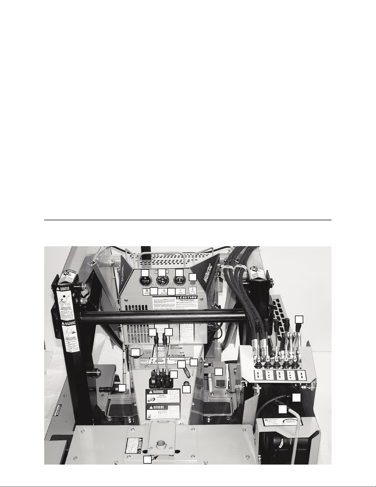
3- CONT OLS
AND
INST UMENTS
Learn the location and purpose of all
controls, instruments, and warning labels.
CONT OLS
(A) PA KING/EME GENCY B AKE
(B) LEFT T ACK CONT OL
(C) IGHT T ACK CONT OL
(D) B AKE LOCK/ ELEASE HANDLE
(E) CHOKE CONT OL
(F) HAND TH OTTLE CONT OL
(G) FOOT TH OTTLE CONT OL
( H ) LIGHT SWITCH
(I) SEAT SAFETY SWITCH
(J) IGNITION SWITCH
(K) OVE D IVE/ACCESSO Y
CONT OL
(L) FAN SWITCH
(M) HOU METE
(N) HYD AULIC OIL TEMPE ATU E
(O) AMMETE
(P) HYD AULIC CI CUIT CONT OL
(Q) HYD AULIC TANK
B EATHE /FILLE
( ) UNLEADED GASOLINE TANK
6
MH8000 Controls & Instruments
A
B
Q
C
D
K
E
F
J
M
P
NO
M
I
LH
G
Verson 8.24.12
(A) PA KING/EME GENCY B AKE
Apply Brake by pushing forward on
its pedal with left foot.
To lock brake lift up on Brake
Lock/Release handle while Pedal (A) is
fully depressed.
To release Parking brake push forward
on Pedal (A) until Brake lock/Release
handle drops
(B) LEFT and (C) IGHT T ACK
CONT OLS
1) To move straight ahead, push both Left and
Right Track Controls forward.
2) To move straight rearward, pull both Left
and Right Track Controls rearward.
3) To turn right, push forward on Left Track
Control.
4) To turn left, push forward on Right Track
Control.
5) To counter-rotate Tracks (shortest turn
possible), push one Track Control forward
while simultaneously pulling rearward on
the other Track Control.
NOTE: When either Track Control lever is
released, it will automatically return to
neutral.
7
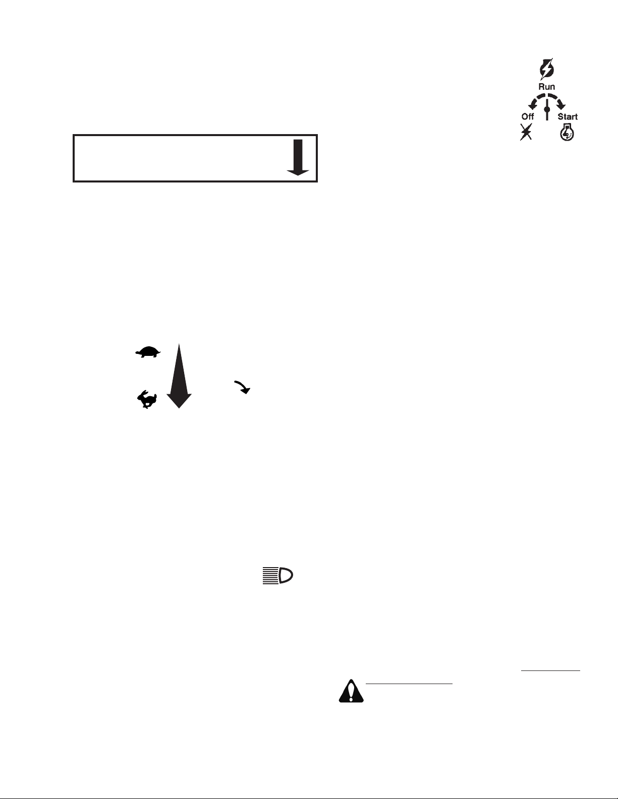
T R A C K
D R I V E
CONTROLS
Neutral
everse
Forward
Neutral
everse
Forward
L
L
E
E
F
F
T
T
R
R
I
I
G
G
H
H
T
T
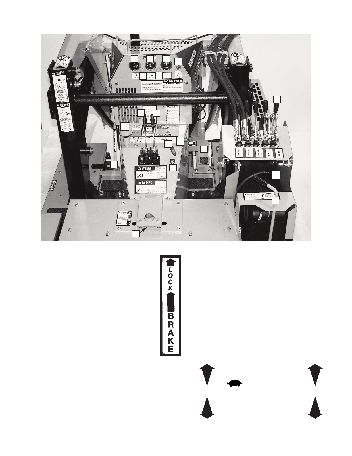
MH8000 Controls & Instruments
A
BC
D
F
E
NOJ
K
L
Q
G
H
I
M
P
(D) B AKE LOCK HANDLE
To release Brake, apply foot pressure to Brake
Pedal (A) and lower Brake Lock Handle (D);
slowly release foot pressure and allow Brake
Pedal to come rearward to its natural unbraked
position.
(E) CHOKE CONT OL
Pull to open engine choke, push to close.
(F) HAND TH OTTLE CONT OL
Pull control handle toward operator to increase
Engine speed...turn handle 1/4 turn clockwise to
lock throttle setting (Do not over-tighten!)
(G) FOOT TH OTTLE CONT OL
The H8000 is also equipped with a foot throttle
control to facilitate changes in engine speed
during operation. Locking the hand throttle at a
desired engine RP will set the lowest operating
RP when foot pedal is released.
(H) LIGHT SWITCH
Pull control handle toward
operator to turn lights on. Push
fully back to turn lights off.
(I) SEAT SAFETY SWITCH
The seat safety switch prevents operation of the
crawler when the operator is not positioned in the
seat. The safety switch may need to be adjusted
to the operator’s weight in order to operate
correctly. See the Service section of this manual
for adjustment procedures.
(J) IGNITION SWITCH
Switch is activated by rotating key
clockwise. Turning it fully clockwise
will engage Engine starter ...
release key and it will return to the
un position. Turn fully counter-
clockwise to Off position to stop
Engine. Remove key.
AUXILIA Y HYD AULIC CONT OLS
An auxiliary bank of Control Valves is located
to the operator’s right. These valves are used to
control all attachments on your tractor. Your
H8000 crawler will contain from one to five of
these valves based on the attachments you have.
(K) OVE D IVE/ACCESSO Y CONT OL
This Overdrive/Accessory Control Valve has two
functions.
1) When pushed fully forward and “locked” into
the Overdrive position, this valve directs the oil
flow of the attachment pump into the track drive
system. When Track Drive Controls are activated,
this feature allows your tractor to gain extra speed
to get out of excavations or move quickly to dump
locations.
In addition, you can travel in “overdrive” for
lighter, higher speed operations. Your tractor will
automatically shift down to regular drive speed
whenever you change an attachment setting
(raise loader, tilt bucket, etc.) then shift back to
overdrive when you are through.
2) When pulled fully rearward and “locked” into
the Accessory position, it directs the oil flow to
optional attachments like our Backhoe, log splitter,
etc. Contact our Service Dept. for more
information on specific hydraulic flow rates,
pressures and various uses for this Accessory
setting.
CAUTION: With Control in “accessory position”
(and its mating Valve Port plugged), all power to
the tracks is lost! Do not leave control in
this position for any period of time!
8
TH OTTLE
pull out
1/4 turn
to lock
Pres s Brak e Ped a l and lower
B AKE LOCK HANDLE to “unlock”
Park i n g Br a k e. M a inta i n Br a k e
adjustment...see Operator ’s Manual.
B AKE
LOCK
HANDLE
LIGHTS
PULL OUT

(L) FAN SWITCH
Your agnatrac H 8000
comes equipped with an
automotive type fan attached to its
external oil cooler. Turn fan on by
pulling switch to help reduce
hydraulic oil temperature in hot
conditions. Turn off fan during extensive use of
headlights to prevent excessive battery drain.
(M) HOU METE
eter will begin recording time
the moment the Ignition Switch
(O) is switched to Run.
NOTE: The Engine does not
have to be running for the eter to record
time...the Ignition Switch just has to be in the un
position. Always turn Ignition Switch Off and
remove key when leaving Crawler. This will
assure you that your eter is recording only
actual running hours!
(N) TEMPE ATU E GAUGE
This gauge records the hydraulic oil
temperature just as it enters the Traction Drive
Pump. onitor this temperature so that it does
not exceed 180 degrees
Fahrenheit.
If the oil temperature
exceeds 180 degrees,
stop operating the
Crawler, but allow the
Engine to operate at
medium speed to circulate the oil through the oil
cooler and lower its temperature.
(O) AMMETE
easures electrical charge or
discharge to battery. If Ammeter
shows a discharge, shut down
electrical system by turning
Ignition Switch to Off and determine the problem.
(P) HYD AULIC CI CUIT CONT OL
The Hydraulic Circuit Control distributes flow
to the HC74 Hydraulic Circuit kit. This flow is
utilized for the PTO70 Power Takeoff option as
well as for other full flow and high pressure
accessories (snow blower, auger, stump grinder,
etc...). If the handle for the Hydraulic Circuit is
turned to the right, even just a little, the tractor will
not start, due to the #441 safety switch installed
on the unit. Never defeat this safety switch!
9
FAN
PULL OUT
HOU S
OIL TEMP.
KEEP BELOW 180°
AMPS

4- OPERATION
PRE-STARTING INSPECTION
Before you start your Crawler for the first
time each day, perform the following checks:
ENGINE COMPARTMENT
Check oil level.
Check air intake system.
Check fuel filter.
Remove trash and oil-dirt deposits.
GRILL AND SIDE PANELS
Remove trash.
Clean oil cooler fins.
TRACKS, ATTACHMENTS, SHEET METAL
Check for bent, broken, or missing parts.
Check Track springs and tension.
HARDWARE
Check for loose or missing parts.
ELECTRICAL SYSTEM
Check for worn or frayed wires or loose
connections.
LUBRICATION
Check lubrication points shown in
eriodic Service section of this manual.
GUARDS AND SHIELDS
Check for tightness and condition.
BATTERY COMPARTMENT
Remove trash.
Check cables for tightness and corrosion.
FUEL TANK
Check fuel level.
HYDRAULIC SYSTEM
Check for leaking lines and connections.
Check for bent or kinked lines.
Check for lines rubbing against each
other or against other parts.
Check oil level.
OPERATOR’S STATION
Check levers for free movement.
Check RO S and Seat Belt.
Clean floor and instrument panel.
Adjust Seat to comfortable height for
operator.
CAUTION - B for you start th ngin :
1) Check the condition of the Crawler. ( re-start
inspection).
2) Be sure there is enough ventilation.
3) Be sure to know the correct starting and
stopping procedure.
4) Sit in the operator’s seat.
5) Clear the work area of people and obstacles.
IMPORTANT: Do not tow or push your
Crawler to start it. You may damage the
hydraulic drive system.
10 Version 8.24.12

PREPARE FOR ENGINE STARTING
1) Fasten Seat Belt (only if you have RO S
installed).
2) Allow Left (B) and Right (C) Track Controls to
assume their natural spring loaded center
neutral positions.
3) ush forward on arking/Emergency Brake
(A) and lift up Lock/Release Handle (D) until
brake locks into position.
4) Check that Loader or front-mounted Bulldozer
Blade is in the fully lowered position, and that
the Backhoe is either in the chain d safe
traveling position, or resting on the ground.
5) Check that all other hydraulic controls are in
their centered neutral position.
NOTE: The hydraulic Accessory Control
(T) does not have a spring load d neutral
centering device; therefore, you must
move it back and forth to determine its
c nt r-n utral position.
6) Make sure you are properly seated so Seat
Safety Switch will engage.
STARTING THE ENGINE
1) lace the Throttle Control (F) midway between
the Slow and Fast positions.
2) Activate the Ignition Switch (J) by rotating it
clockwise until starter engages. Release the
switch as soon as the Engine starts...Switch
will return to the Run position.
CAUTION: Do not crank the Engine
continuously for more than 10 seconds at a
time. If the Engine does not start, allow a
60-second cool-down period between
starting attempts. Failure to follow these
guidelines can burn out the starter motor.
CAUTION: If the Engine develops sufficient
speed to disengage the starter but does not
keep running (a “false start”), the Engine
rotation must be allowed to come to a
complete stop before attempting to restart
the Engine.
If the starter is engaged while the flywheel is
rotating, the starter pinion and flywheel ring gear
may clash, resulting in damage to the starter.
If the starter does not turn the Engine over,
shut off starter immediately. Do not make further
attempts to start the Engine until the condition is
corrected.
If the battery charge is not sufficient to turn
over the engine, recharge the battery.
CAUTION: Do not attempt to jump start the
engine with another battery. Starting with
batteries larger than those recommended
can burn out the starter motor.
WARM-UP PERIOD
1. Run Engine at half speed for 5 minutes.
2. Do not run Engine at fast, or slow idle.
3. Operate Crawler at less-than-normal loads
and speeds for the first 15 minutes.
WARNING: L thal Exhaust Gas s
Engine exhaust gases contain poisonous
carbon monoxide. Avoid inhaling fumes, and
never run the Engine in a closed building or
confined area.
NOTE: Assembled Crawlers are “run in” under
no load at the factory for 20 - 30 minutes to
properly break-in their drive train and track drive
motors, and to test hydraulic systems.
USE SEAT BELT
CAUTION: Use a Seat Belt when you
operate with a Roll-Over rotective
Structure (RO S) to minimize chance of
injury from an accident such as an overturn.
Do not use a Seat Belt if operating without a
RO S.
TRAVELING
ush forward on arking Brake (A) and lower
Brake Lock (D); slowly release pressure on
arking Brake and allow it to come back to its
natural “rearward” position...remove foot from
Brake!
Raise all attachments to their recommended
traveling heights.
A) To mov straight ah ad, simultaneously
push Right Track Control (C) and Left
Track Control (B) forward.
11

B) To mov straight to th r ar, simultaneously
pull both Right and Left Track Controls
rearward.
C) To turn to th right, push Left Track Control
forward.
D) To turn to th l ft, push Right Track Control
forward.
E) To count r-rotat Tracks, (shortest turn
possible), push one Track Control forward
while simultaneously pulling rearward on
the other Track Control.
NOTE: The Right and Left Track Controls are
of the self-centering (neutral) “deadman” type.
This allows you to simply let go of both Track
Controls to disconnect active power to the Tracks.
F) Parking/Em rg ncy Brak (A) will stop or
hold Crawler in the neutral drive position.
PARKING THE CRAWLER
1) Lower all equipment to the ground.
2) Allow Right and Left Track Controls to go to
neutral.
3) ush forward on Brake and lift lock handle to
engage parking brake.
4) Run Engine at half speed 2 minutes without
load.
5) Move Throttle Control to slow idle.
6) Turn Ignition Switch to Off.
7) Release hydraulic pressure by “rocking” all
hydraulic controls back and forth.
IMPORTANT: If Engine stops under load,
remove load. Start Engine immediately. Run 30
seconds at half speed before adding load.
NOTE: If engine stops, you must turn key Off
before you can start the engine.
IMPORTANT: In freezing weather, park on a
hard surface to avoid freezing the Tracks to the
ground. If Tracks are frozen to the ground, be
careful to avoid damage to the Tracks and drive
train when you try to move the Crawler. When
storing your tractor for an extended period of time,
make sure to store it away from any moisture.
Moisture in contact with the steel tracks over an
extended period of time will rust. Lubricate the
track chains and the drive chains as specified in
this manual.
CAUTION: When you park your Crawler
on a slope, put blocks against tracks. Do
not park Crawler with tracks pointed
downhill.
12

5- FUELS and LUBRICANTS
FUELS
FUEL SPECIFICATIONS
Check enclosed Engine Owner’s Manual and
closely follow their recommendations.
FILLING FUEL TANK
The Fuel Tank is located to the right of
the operator’s seat. It is filled by removing
the 3” dia. Cap marked with the universal
Gasoline symbol (shown at left). Use fuel grade
per Engine Owner’s Manual shipped with your
MH8000... tighten Cap securely when finished
filling.
CAUTION:DO NOT confuse the Fuel
Tank with the Hydraulic Oil Tank which is
filled by removing the #616 (Q) Breather
Cap from the Coupling on top left of Magnatrac’s
dash.
Fill Fuel tank at end of each day’s operation.
Fuel tank capacity is approximately 5 U.S.
gallons.
CAUTION: Handle fuel carefully. Do not fill fuel
tank when the Engine is running. Do not smoke
while you fill fuel tank or work on fuel system.
STORING FUELS
eep fuel in a container in a protected area.
Water and sediment must be removed before fuel
gets to the Engine. Do not depend on fuel filters
to remove water.
If possible, install a water separator at the
storage tank outlet.
Store fuel drums on their sides with plugs up.
IMPORTANT: eep all dirt, scale, water, or
other foreign matter out of fuel.
LUBRICANTS
ENGINE OIL
Check enclosed Engine Owner’s Manual and
closely follow their recommendations.
HYDRAULIC OIL
Use a premium quality hydraulic oil with
maximum anti-wear properties, rust and oxidation
treatment. A high quality antiwear hydraulic fluid
designed for use in high pressure, high speed
hydraulic pumps in industrial hydraulic systems.
We use a Conoco (Phillips 66, 76), Megaflow AW
Hydraulic Oil 32. (ISO V632). 10 Weight.
Product Code: 1055927. An ISO of 32 is good for
“oil” temperature conditions of +5F to +170F
which are considered standard.
If the above specifications can not be found
consult with a local tractor/equipment dealership
or oil supplier for other brands of hydraulic oil
suitable for loaders, backhoe, and hydraulic drive
systems.
Fill Hydraulic Oil Tank through coupling on top
left of Dash, check level with #248 Dipstick
[Dipstick found below & inside #616 Breather Cap]
...remove Breather with a wrench before filling!
Approximately 12.5 gallons of hydraulic fluid fill
the hydraulic reservoir to the proper level.
GREASE
Use premium quality SAE Multi-Purpose
Grease.
STORE LUBRICANTS in clean containers in
area protected from dust, moisture, &
contamination.
13 Version 8.24.12

6- LUBRICATION and
PERIODIC SERVICE
HOUR METER
Use the Hour Meter (M) to determine when
periodic services are required. Should the hour
meter not be installed, keep a usage log for your
equipment to maintain service intervals.
LUBRICATION AND SERVICE
INTERVALS
IMPORTANT: Recommended service intervals
are for normal conditions. Service more often if
Crawler is operated under difficult conditions.
Such as extreme heat, dusty conditions, and daily
use for extended period of time.
IMPORTANT: Use only quality lubricants at
intervals specified in this manual.
PERIODIC SERVICE CHART
EVER TEN HOURS
EVER TEN HOURS
Air Cleaner(s) - Service per instructions in
Engine Owner’s Manual. The Engine has
an inner air cleaning element
(replacement part #1365) inside the
standard air cleaner body.
Engine Oil - Service per instructions in Engine
Owner’s Manual...replacement Engine Oil
Filter is #1367.
Hydraulic Oil - Check level; with equipment on
the ground (retract all possible cylinders),
level should be between marks on #248
Dipstick (Dipstick can be found when you
unscrew and remove #616 (Q) Breather
with a wrench. Don’t try to use a
screwdriver to unscrew the top cap. (See
page 17)...replacement Hydraulic Oil Filter
is #455B.
Grease Fittings - ubricate all grease fittings per
location instructions in manual of each
attachment you have mounted on your
Crawler. Recommended grease:
Multipurpose NLGI 2 Grade Lithium
Complex, ISO VG 220.
A small breakdown of how many grease
fittings are on each MH8000 tractor and
various Attachments is as follows.
MH8000: 14
For an MH8000, all grease fittings will be
on the outside of every Axle & Pin, except
for the Front Idler axle. On the Front Idler
axle, it is on the
inside end
of the welded
tube. Hint: You may have to rotate the
tracks to find these grease fittings. (See
Photo MH-12)
H 900, H 950, H 975: 12
D108: 21
D1065: 18
D1060: 14
For all others, please see each individual
attachment for the quantity of grease
fittings. As a standard guide, there will be
a zerk for each Axle & Pin that you see on
a particular attachment.
Oil Cooler - With
low pressure
air, blow clean the
“fins” of the oil cooler.
Track Tension - Maintain overall tightness of
each track. When your tractor leaves our
factory, the outside, black, #234 spring
measurement is 4 1/2 in. The inside,
yellow, #233 spring measurement WILL
NOT be the same! The most important
thing is for the front axle to be square. In
addition, check that the #235 washer
against the front face of each #215 Front
Axle is not loose enough to be rotated with
fingers. Check Service section of this
manual for complete explanation and
Track tensioning procedures. (See
Drawing MH-B and Photo MH-13.
Fittings & Hoses - Check hydraulic fittings and
hydraulic hoses for cracks, breaks, and
leaks.
General Once-Over - Check for loose nuts and
bolts and any signs of premature wear.
Correct any problems immediately.
NOTE: Check “NOTE” in Service Section
of this manual for information on Track
Idler wear!
14 Version 8.24.12
Table of contents
Other Struck Tractor manuals


