Case JX1060V User manual

MDB1965A
JX1060V -- JX1070V -- JX1075V --
JX1070N -- JX1075N TRACTORS
SERVICE MANUAL
SECTIONS
GENERAL GUIDELINES 00........................................
ENGINE 10......................................................
CLUTCH 18......................................................
TRANSMISSIONS 21..............................................
DRIVE LINES 23..................................................
FRONT MECHANICAL TRANSMISSION 25..........................
REAR MECHANICAL TRANSMISSION 27...........................
POWER TAKE- OFF 31............................................
BRAKES 33......................................................
HYDRAULIC SYSTEMS 35........................................
STEERING 41....................................................
AXLE AND WHEELS 44...........................................
CAB AIR CONDITIONING SYSTEM 50.............................
ELECTRICAL SYSTEM 55.........................................
CAB 90..........................................................
TECHNICAL SUPPORT

2SECTION 10 -- ENGINE -- CHAPTER 1
6- 62730 -- 04 -- 2004
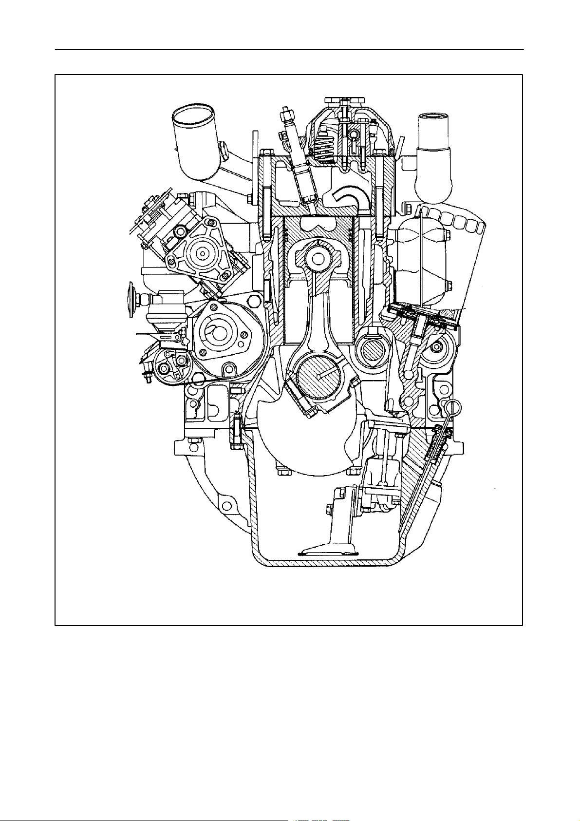
GENERAL SPECIFICATIONS
Engine, technical type:
-- Mod. JX1060V -- type 8035.05C.925/929 (BOSCH pump) .............. See data on page 6--7
-- Mod. JX1070V and JX1070N -- type 8035.25R.925/929 (BOSCH pump) . . See data on page 8--9
-- Mod. JX1075V and JX1075N -- type 8035.25.925/929 (BOSCH pump) . . . See data on page 10--11
Cycle ............................................................... diesel, 4--stroke
Fuelinjection ........................................................ direct
Number of cylinders in line ............................................. 3
Cylinder liners ....................................................... dry force--fitted in cylinder
block
Piston diameter
-- Mod. JX1060V .................................................... 4.0944 in. (104 mm)
-- Mod. JX1070V and JX1070N ...................................... 4.0944 in. (104 mm)
-- Mod. JX1075V and JX1075N ...................................... 4.0944 in. (104 mm)
Pistonstroke ........................................................ 4.5275 in. (115 mm)
Total displacement:
-- Mod. JX1060V .................................................... 178.84 in3(2931 cm3)
-- Mod. JX1070V and JX1070N ....................................... 178.84 in3(2931 cm3)
-- Mod. JX1075V and JX1075N ....................................... 178.84 in3(2931 cm3)
Compression ratio for Mod. JX1060V, JX1070V and JX1070N .............. 17:1 normally aspirated
Compression ratio for Mod. JX1075V and JX1075N ....................... 16.5:1 turbocharged
Maximum power:
-- Mod. JX1060V .................................................... 43.5 kW (59 Hp)
-- Mod. JX1070V and JX1070N ....................................... 53 kW (72 Hp)
-- Mod. JX1075V and JX1075N ....................................... 55.5 kW (76 Hp)
Maximum power speed ............................................... 2300 rpm
Maximum torque speed for Mod. JX1060V ............................... 1400 rev/min
Maximum torque speed for Mod. JX1070V and JX1070N .................. 1400 rev/min
Maximum torque speed for Mod. JX1075V and JX1075N .................. 1400 rev/min
Number of main bearings .............................................. 4
Sump ............................................................... structural, cast iron
(continued)

SECTION 10 -- ENGINE -- CHAPTER 1 23
6- 62730 -- 04 -- 2004
1
2
345
6
7
25355
3
Longitudinal section of engine (mod. JX1060V).

24 SECTION 10 -- ENGINE -- CHAPTER 1
6- 62730 -- 04 -- 2004
25356
4
Cross--section of engine (mod. JX1060V).

SECTION 10 -- ENGINE -- CHAPTER 1 25
6- 62730 -- 04 -- 2004
5
5335B
1
2
3
4
5
6
7
8
6
1
3
8
5335A
Engine lubrication system diagram
1. Oil filler cap -- 2. Filter safety valve (opens when oil pressure at filter inlet exceeds the outlet pressure by 1.5--1.7 bar/cm2) -- 3. Filter --
4. Engine lubrication oil low pressure indicator lamp switch (located on the dashboard) -- 5. Dipstick -- 6. Pump -- 7. Oil pressure limiting valve --
8. Mesh filter on intake

26 SECTION 10 -- ENGINE -- CHAPTER 1
6- 62730 -- 04 -- 2004
1 2
3
4
5
6
25363
ab
6
Engine cooling system circuit diagram.
A. Coolant circulation with thermostat valve
closed
B. Coolant circulation with thermostat valve open
1. Thermostat
2. Pump
3. Electric thermometer for engine coolant
temperature
4. Temperature transmitter
5. Fan
6. Radiator

SECTION 10 -- ENGINE -- CHAPTER 1 31
6- 62730 -- 04 -- 2004
Op. 10 001 10
ENGINE Removal--Installation
DANGER
Lift and handle all heavy parts using suitable lifting
equipment.
Make sure that assemblies or parts are supported by
means of suitable slings and hooks. Check that no
one is in the vicinity of the load to be lifted.
CAUTION
Always use appropriate tools to align fixing holes.
NEVER USE FINGERS OR HANDS.
Proceed as follows.
1. Carry out operation 90 150 10 Cab with platform
unit, only removal (see Sect. 90) (models with
cab).
NOTE: Make sure that the bracket 380001613 lock-
ing the front axle in relation to the engine is positioned
and secured between the above.
2. Carry out operation 90 110 36 Platform assembly
only removal (see Sect. 90) (models with plat-
form).
3. Carry out operation 90 114 20 Front roll bar, only
removal (see Sect. 90) (models with platform).
4. Unscrew the plug and drain the oil from the rear
transmission casing (the prescribed quantity is
11.09 US gal. (42 litres)). 25628
7
5. Disconnect the electrical connections (2) and re-
move the front guard (1) by sliding forwards.
8

32 SECTION 10 -- ENGINE -- CHAPTER 1
6- 62730 -- 04 -- 2004
6. If the tractor is not fitted with an extra fuel tank,
disconnect the piping (1) and drain the fuel from
the main tank.
7. If the tractor is fitted with a platform the coolant
must be drained.
9
8. Disconnect the fuel return piping (1).
10
9. Remove the clamp (1) and detach the radiator
sleeve (2), unscrew the radiator retaining bracket
(3).
11
10. Disconnect the connecting pipe (1) between the
main fuel tank and the extra fuel tank.
12

SECTION 10 -- ENGINE -- CHAPTER 1 33
6- 62730 -- 04 -- 2004
11. Unscrew the brake control piping (1) on the front
axle.
13
12. Disconnect the hydrostatic steering piping (1).
14
13. Disconnect the steering sensor wire, loosen the
hose and wire retaining clamps (1) on the radi-
ator.
15
14. Loosen the clamp and disconnect the fuel injec-
tion pump hose (1).
16

34 SECTION 10 -- ENGINE -- CHAPTER 1
6- 62730 -- 04 -- 2004
15. Unscrew the clamp (1) to release the sleeve (2)
from the turbocharger.
16. Disconnect the electrical connections (1) on the
clogged air filter sensor.
17
17. Unscrew the clamp and remove the sleeve (1) on
the relative rigid pipe (2).
18
18. Loosen the hydraulic pump line piping bolts (1).
19
19. Loosen the clamps (1, 3 and 4), unscrew the
bracket retaining bolts (2) and remove the hy-
draulic pump line piping (5).
20

SECTION 10 -- ENGINE -- CHAPTER 1 35
6- 62730 -- 04 -- 2004
20. Unscrew the filter piping (1 and 2).
21. Unscrew the services distributor piping (3, 4 and
5).
21
22. Disconnect and remove piping (1, 2, 3, 4, 5 and
6).
23. Carry out operation 10 254 44 Exhaust pipe, only
removal (see Sect. 10).
22
24. Disconnect the piping (2), unscrew the clamp (1),
the piping/clutch housing retaining bolt, and re-
move piping (1 and 3).
23
25. Remove the guard (2) and disconnect the starter
motor wires (1), disconnect the pipe (4).
26. Remove the retaining clamp and disconnect the
engine electrical wires, place the wires (2 and 3)
on the clutch casing.
24

36 SECTION 10 -- ENGINE -- CHAPTER 1
6- 62730 -- 04 -- 2004
27. Disconnect the brake piping (1) from the block.
28. Carry out operation 23 101 26 Propeller shafts
and guard, only removal (see Sect. 23).
25
29. Position an hydraulic jack under the rear axle, at-
tach the motor to a hoist, using a chain, and place
a stand under the clutch casing.
30. Unscrew the front axle -- engine retaining bolts
(1).
26
31. Remove the front axle, complete with support,
tanks, radiator and air filter.
27
32. Unscrew the bolt (2) accessing the Allen screw
(1) (on both sides).
28

SECTION 10 -- ENGINE -- CHAPTER 1 37
6- 62730 -- 04 -- 2004
33. Unscrew all of the clutch casing -- engine bolts
and detach the engine.
34. To re--fit the engine, proceed as follows.
CAUTION
Always use appropriate tools to align fixing holes.
NEVER USE FINGERS OR HANDS.
-- Apply the torque settings listed on page 20.
-- Before refitting the engine to the clutch box care-
fully clean the mating surfaces and apply sealing
compound (0.0787 in. (2 mm) diameter), accord-
ing to the diagram shown Section 21, Chapter 1,
page 29.
-- Fit the engine on the clutch casing.
-- Re--fit the front axle support assembly on the en-
gine.
-- Carry out operation 23 101 26 Propeller shafts
and guard, only installation (see Sect. 23).
-- Connect the brake piping.
-- Connect the wires to the starter motor and posi-
tion the other wires on the engine.
-- Assemble all hydraulic pipes and hoses.
-- Carry out operation 10 254 44 Exhaust pipe, only
installation (see Sect. 10).
-- Assemble the hydraulic pump feed piping, com-
plete with the relative support bracket.
-- Connect the lower radiator sleeve to the rigid
pipe.
-- Place the inlet sleeve on the turbocharger and
secure in position.
-- Connect the electrical connections to the
clogged air filter sensor.
-- Connect the injection pump fuel supply piping.
-- Connect the steering sensor wire.
-- Fit the hydrostatic steering piping to the radiator.
29
-- Connect the hydrostatic steering piping.
-- Connect the brake piping on the front axle.
-- Connect and secure the main fuel tank/extra fuel
tank piping.
-- Connect the upper radiator sleeve.
-- Attach the radiator bracket.
-- Connect the fuel return piping to the fuel tank.
-- Position the front guard and connect the head-
lamps and direction indicator electrical connec-
tions.
-- Screw the plug on the rear transmission casing
and fill up with oil (see page 6, Sect. 00 for pre-
scribed products and quantities).
-- Carry out operation 90 114 20 Removable front
roll bar, only re--assembly (see sect. 90) (models
with platform).
-- Carry out operation 90 110 36 Platform assem-
bly, only installation (see Sect. 90) (models with
platform).
-- Carry out operation 90 150 10 Cab with platform
unit, only installation (see Sect. 90) (models with
cab).
-- Fill up the engine cooling system (see page 6,
Sect. 00 for prescribed products and quantities).
-- Fill up the fuel tank (see page 6, Sect. 00 for pre-
scribed products and quantities).
-- Bleed the brakes (see Sect. 33).

38 SECTION 10 -- ENGINE -- CHAPTER 1
6- 62730 -- 04 -- 2004
Op. 10 001 30 COMPRESSION TEST
In case of poor engine performance, in addition to
checking the fuel injection system (injection nozzles
and injection pump), also test the compression on
each cylinder.
DANGER
Do not use matches, lighters, blowtorches or any
form of naked flame as a source of light when in-
specting the engine due to the presence of flam-
mable fluids and vapour.
Compression ratio
The compression ratio is a measure of the quantity
of air drawn into the cylinder, and provides an indica-
tion of the efficiency of the sealing elements in the
cylinder (piston rings and valves).
Uniform compression in all the cylinders ensures that
they all perform an equal amount of work, provided
that each cylinder is injected with the same quantity
of fuel at the right time.
Low compression not only reduces engine perform-
ance, it also causes incomplete fuel combustion due
to the lack of available combustion air.
The engine therefore gives poor performance with
excessive fuel consumption and, consequently, ex-
haust smoke and restriction of the exhaust pass-
ages.
As the compression ratio also varies with the tem-
perature of the engine (cold engines produce lower
compression values than hot engines), the compres-
sion should only be tested when the engine is at nor-
mal operating temperature.
Compression should be tested using the compres-
sion test kit 380000303, as follows:
1) run the engine until it reaches normal operating
temperature;
2) switch off the engine;
3) disconnect the lead from the engine stop electro-
magnet on the injection pump in order to close the
valve and block the flow of fuel to the injectors;
4) remove the injector from the cylinder to be tested;
5) turn the engine over a few times with the starter
motor in order to expel any carbon residue;
6) fit the dummy injector 380000617 in place of the
injector removed previously, inserting the copper
sealing washer;
7) connect the compression test instrument
380000303 and take readings while turning the en-
gine over with the starter motor.
On engines in perfect working order, with the sump
oil at approx. 104 °F(40°C) at sea level (29.9212 in.
(760 mm) mercury) and at an engine speed of 200 to
280 rpm, the compression should be 369.75 to
398.75 psi (25.5 to 27.5 bar).
8) Test the compression on the other cylinders, re-
peating steps 4--5--6--7, bearing in mind that:
The minimum permissible compression on a used
engine is 313.2 psi (21.6 bar).
The maximum permissible compression difference
between cylinders is 43.5 psi (3 bar).
Every 100 metres above sea level corresponds to a
reduction in compression by approx. 1%.
CONSIDERATIONS:
Uniform compression
Although high compression is important, it is more
important for smooth engine running that compres-
sion is uniform in all cylinders.
Low compression readings.
If extremely low pressure readings are obtained on
one cylinder it is advisable to repeat the test.
Before testing this time, pour about a spoonful of en-
gine oil into the cylinder through the injector bore.
Turn over the engine a few times to distribute the oil
evenly over the cylinder walls, and then repeat the
test.
If the second test readings are significantly higher,
suspect worn piston rings, out--of--round or damaged
pistons or liners.
If the second test readings are not higher, the prob-
lem will be the valves.
On the other hand, if the second test reading shows
only a slight improvement, the problem will be due to
both the valves and the rings.
This manual suits for next models
4
Table of contents
Other Case Tractor manuals