STT Emtec SCRmarine Instruction sheet
Page 1Document
STT SCRmarine
Installation Guideline
Date
2014-08-27 Issue: 1.6
STT Emtec AB (pbl)
Kontorsvägen 9
SE-852 29 SUNDSVALL
SWEDEN
Tel: +46 (0)60-64 10 40
Fax: +46 (0)60 64 10 45
e-mail: info@sttemtec.com
Internet: www.sttemtec.com
Head office: Sundsvall
Org.nr: 55 62 05 – 2927
VAT ID: SE556205292701
ISO-cetrifikat nr: 15627
Installation Guideline
This guideline describes the recommended installation procedure and maintenance for the STT SCRmarine system
Latest version available at www.sttemtec.com
Page 2Document
STT SCRmarine
Installation Guideline
Date
2014-08-27 Issue: 1.6
STT Emtec AB (pbl)
Kontorsvägen 9
SE-852 29 SUNDSVALL
SWEDEN
Tel: +46 (0)60-64 10 40
Fax: +46 (0)60 64 10 45
e-mail: info@sttemtec.com
Internet: www.sttemtec.com
Head office: Sundsvall
Org.nr: 55 62 05 – 2927
VAT ID: SE556205292701
ISO-cetrifikat nr: 15627
Table of content
1. Purpose
2. The SCR technology
2.1. The STT SCRmarine system
2.2. Catalyst and POC
2.2.1 SCR Catalyst configurations
2.2.2 POC
2.2.3 Noise reduction
2.2.4 Catalyst
2.2.5 Thermal expansion
2.3. Mixer assembly & injection nozzle
2.3.1 Replacing the injection nozzle
2.4. Urea dosing unit (UDS)
2.4.1 Installation
2.4.2 Replacing the urea dosing unit
2.4.3 Replacing the DEF filter
2.4.4 Adjusting the main air pressure
2.4.5 Adjusting the secondary air pressure
2.5. Urea/air lines & connections
2.5.1 Urea line, from tank to dosing unit
2.5.2 Urea nozzle, from dosing unit to mixer
2.5.3 Urea line, from dosing unit to tank
2.6. Urea tank
2.7 Insulation
3. Electrical and pneumatic system
3.1 NOx concentration sensor
3.2 Exhaust temperature sensors
3.3 Exhaust back pressure sensor
3.4 Monitoring system
3.5 Control cabinet
3.6 Wiring harness and hose/tube length information
3.7 Wiring, layout drawing
4. Post installation adjustments and inspection
5. Service and maintenance
5.1 Required service
5.1.1 Control cabinet
5.1.2 Urea lines / connections
5.1.3 Flange connections
5.1.4 Injection nozzle and mixer unit
5.1.5 Mixer unit
5.1.6 DEF filter
Page 3Document
STT SCRmarine
Installation Guideline
Date
2014-08-27 Issue: 1.6
STT Emtec AB (pbl)
Kontorsvägen 9
SE-852 29 SUNDSVALL
SWEDEN
Tel: +46 (0)60-64 10 40
Fax: +46 (0)60 64 10 45
e-mail: info@sttemtec.com
Internet: www.sttemtec.com
Head office: Sundsvall
Org.nr: 55 62 05 – 2927
VAT ID: SE556205292701
ISO-cetrifikat nr: 15627
6. Technical specifications
6.1 Urea dosing unit (UDS)
6.2 Nozzle
6.3 Urea line, tank - - dosing unit
6.4 Urea line, dosing unit - - tank
6.5 Main air regulator
6.6 Urea tank
6.7 POC
6.8 Catalyst
6.9 Control cabinet
Appendix 1 Assembly drawings
Appendix 2 Wiring connection and length diagram
Appendix 3 Post installation adjustment and inspection
Appendix 4 Trouble shooting guide
Appendix 5 Commissioning prerequisites
Appendix 6 Adblue® safety manual
Appendix 7 Installing analogue sensors

Page 4Document
STT SCRmarine
Installation Guideline
Date
2014-08-27 Issue: 1.6
STT Emtec AB (pbl)
Kontorsvägen 9
SE-852 29 SUNDSVALL
SWEDEN
Tel: +46 (0)60-64 10 40
Fax: +46 (0)60 64 10 45
e-mail: info@sttemtec.com
Internet: www.sttemtec.com
Head office: Sundsvall
Org.nr: 55 62 05 – 2927
VAT ID: SE556205292701
ISO-cetrifikat nr: 15627
1 Purpose
The purpose of this document is to give sufficient information on how to use and install the key
components of the SCRmarine system. The installation guideline also describes the post
adjustments and inspection processes and gives general information on service and maintenance.
2 The SCR technology
NOx, nitrogen oxides, produced during the combustion process in diesel engines is a contributing
factor to air pollution. In an SCR system (Selective Catalytic Reduction) the injected urea reacts
over the catalyst with the harmful NOx gases in the exhaust and converts it to water and nitrogen.
4NH 3 + 4NO + O2→4N2+ 6H2O
The urea is a clear, non-toxic chemical. It is in normal conditions safe to handle and is not harmful
to the environment. To be able to inject the urea into the exhaust, a mixture of urea diluted in
distilled water, called DEF is used. Urea can cause corrosion to metal parts, therefore the handling
equipment must be designed to withstand urea. This applies to tanks, pumps, lines, etc.
In this document the common names DEF and urea are used instead of trade names.
It is important to only use urea liquid controlled by the DIN 70070-standard.
Note! The fuel quality for the SCR system must fulfill EN 590.
Note! If a POC is used in combination with SCR or as a stand alone unit, the fuel
quality must fulfill EN 590.
For other fuel qualities please contact Stt Emtec AB for consultation.
Figure 1 on the next page is a general component location guide for the urea system.
Page 5Document
STT SCRmarine
Installation Guideline
Date
2014-08-27 Issue: 1.6
STT Emtec AB (pbl)
Kontorsvägen 9
SE-852 29 SUNDSVALL
SWEDEN
Tel: +46 (0)60-64 10 40
Fax: +46 (0)60 64 10 45
e-mail: info@sttemtec.com
Internet: www.sttemtec.com
Head office: Sundsvall
Org.nr: 55 62 05 – 2927
VAT ID: SE556205292701
ISO-cetrifikat nr: 15627
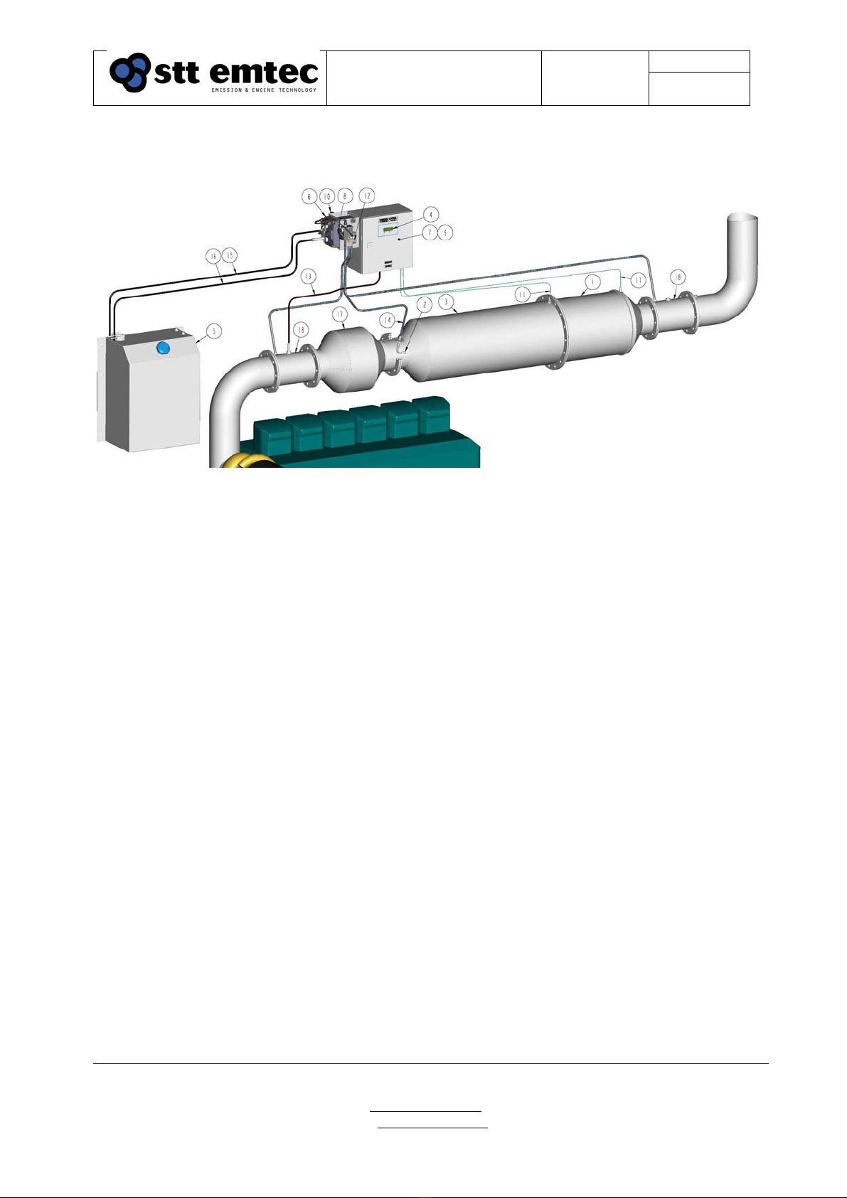
2.1 The STT SCRmarine system
Figure 1. SCR marine system configuration
1. SCR Catalyst, 2. Injection point, 3. Mixer unit, 4. Diagnostic display, 5. Urea tank, 6. Urea dosing unit,
7. Electronic control unit (ECU), 8. Urea pressure sensor, 9. Control cabinet, 10. Air pressure regulator,
11. Temperature sensor, 12. Exhaust pressure sensor, 13. NOx sensor, 14. Urea nozzle,
15. Urea line; from pump to tank. 16. Urea line; from tank to pump, 17. POC (Option),
18. Sensor adapter exhaust pipe (Option).

Page 6Document
STT SCRmarine
Installation Guideline
Date
2014-08-27 Issue: 1.6
STT Emtec AB (pbl)
Kontorsvägen 9
SE-852 29 SUNDSVALL
SWEDEN
Tel: +46 (0)60-64 10 40
Fax: +46 (0)60 64 10 45
e-mail: info@sttemtec.com
Internet: www.sttemtec.com
Head office: Sundsvall
Org.nr: 55 62 05 – 2927
VAT ID: SE556205292701
ISO-cetrifikat nr: 15627
2.2 Catalyst and POC
2.2.1 SCR Catalyst configurations
The STT SCRmarine system is a modular system based on the same type of key components for
each engine size. Different SCR catalyst diameter and length are used for the different
configurations. The larger SCR catalysts LA to LC are housed in a 15 inch canning and the
smaller systems, MD and ME uses a 11.25 inch canning.
A recommendation table based on the rated power of the engine is presented in figure 2.
0
1
2
3
4
5
6
7
8
0 100 200 300 400 500 600 700 800
Rating (kW)
SCR Setup
ME
MD
LC
LB
LA
XA
XB
Figure 2. System size recommendation determined by engine power rating
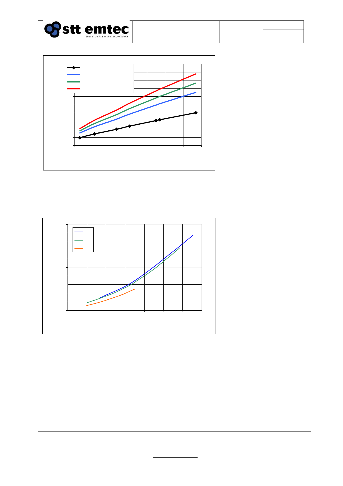
The additional exhaust backpressure caused by the pressure drop over the SCR catalyst
configuration is dependent on the actual exhaust volume flow. The actual volume flow can be
calculated from the exhaust mass flow, available from the engine specification sheet, and the
measured exhaust temperature at a point near the catalyst inlet.
Figure 3 presents typical exhaust mass flow rates versus rated engine power together with the
corresponding volume flows at exhaust temperatures from 300 to 500°C.
Note that this data is a guideline only and that data from the engine manufacturer are to be used
for determine the proper SCR catalyst configuration.
Page 7Document
STT SCRmarine
Installation Guideline
Date
2014-08-27 Issue: 1.6
STT Emtec AB (pbl)
Kontorsvägen 9
SE-852 29 SUNDSVALL
SWEDEN
Tel: +46 (0)60-64 10 40
Fax: +46 (0)60 64 10 45
e-mail: info@sttemtec.com
Internet: www.sttemtec.com
Head office: Sundsvall
Org.nr: 55 62 05 – 2927
VAT ID: SE556205292701
ISO-cetrifikat nr: 15627
0
1000
2000
3000
4000
5000
6000
7000
8000
9000
10000
100 200 300 400 500 600 700 800
Power(kW)
Exhaust flow (kg/h, M3/h)
Kg/h
M3/h (@ 300 deg C)
M3/h (@ 400 deg C)
M3/h (@ 500 deg C)
Figure 3
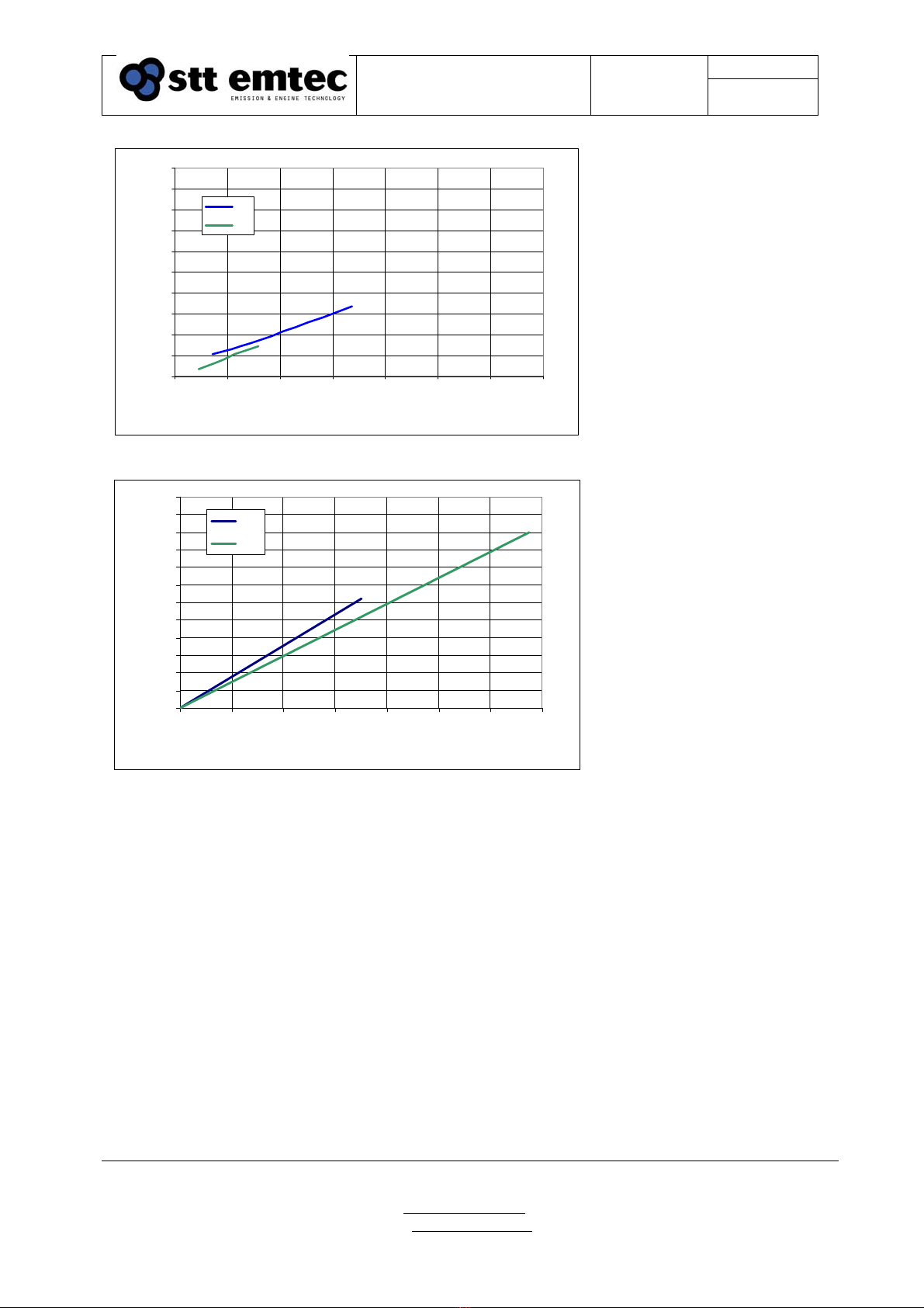
Depending on the SCR catalyst configuration the total pressure drop including the urea mixer unit
are displayed in figure 4 to 6.
0
20
40
60
80
100
120
140
160
180
200
0 1000 2000 3000 4000 5000 6000 7000
Actual Exhaust Volume Flow (M3/h)
Pressure drop (mbar)
LA
LB
LC
Figure 4
Page 8Document
STT SCRmarine
Installation Guideline
Date
2014-08-27 Issue: 1.6
STT Emtec AB (pbl)
Kontorsvägen 9
SE-852 29 SUNDSVALL
SWEDEN
Tel: +46 (0)60-64 10 40
Fax: +46 (0)60 64 10 45
e-mail: info@sttemtec.com
Internet: www.sttemtec.com
Head office: Sundsvall
Org.nr: 55 62 05 – 2927
VAT ID: SE556205292701
ISO-cetrifikat nr: 15627
0
20
40
60
80
100
120
140
160
180
200
0 1000 2000 3000 4000 5000 6000 7000
Actual Exhaust Volume Flow (M3/h)
Pressure drop (mbar)
MD
ME
Figure 5
0
10
20
30
40
50
60
70
80
90
100
110
120
0 2000 4000 6000 8000 10000 12000 14000
Actual Exhaust Volume Flow (M3/h)
Pressure drop (mbar)
XA
XB
Figure 6
The pressure drop curves that are displayed in the graphs above are a measured value of the
differential pressure over the SCR catalysts and mixer unit. It doesn’t include bends, silencers or
additional piping.
Page 9Document
STT SCRmarine
Installation Guideline
Date
2014-08-27 Issue: 1.6
STT Emtec AB (pbl)
Kontorsvägen 9
SE-852 29 SUNDSVALL
SWEDEN
Tel: +46 (0)60-64 10 40
Fax: +46 (0)60 64 10 45
e-mail: info@sttemtec.com
Internet: www.sttemtec.com
Head office: Sundsvall
Org.nr: 55 62 05 – 2927
VAT ID: SE556205292701
ISO-cetrifikat nr: 15627
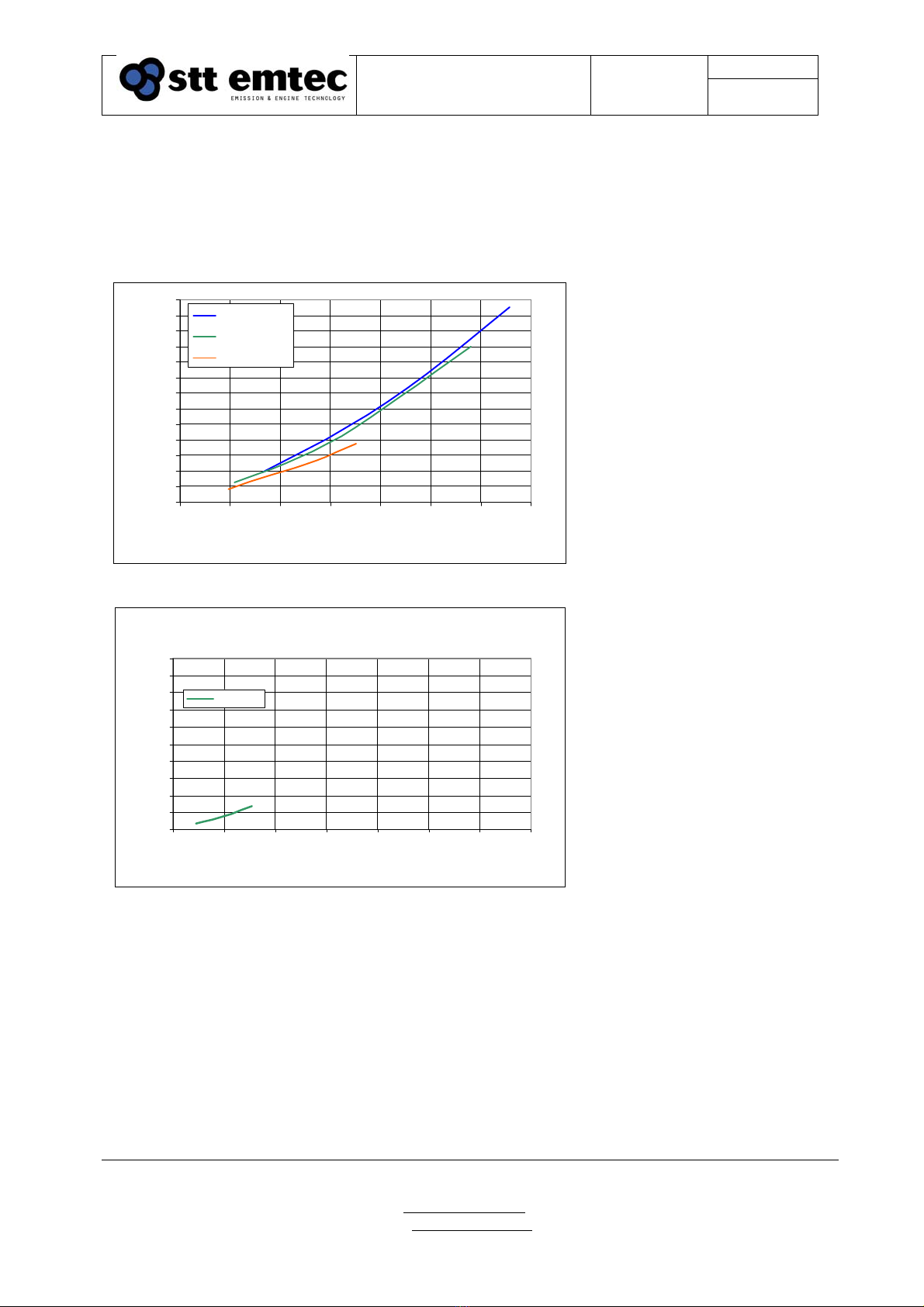
If the option with a POC upstream of the SCR system is used pressure drop over the complete
system (POC, urea mixer and SCR catalyst) will increase by approximately 60%. The total
pressure drop including the urea mixer unit are displayed in figure 7 and 8
0
20
40
60
80
100
120
140
160
180
200
220
240
260
0 1000 2000 3000 4000 5000 6000 7000
Actual Exhaust Volume Flow (M3/h)
Pressure drop (mbar)
LA + POC
LB + POC
LC + POC
Figure 7
ME + POC
0
20
40
60
80
100
120
140
160
180
200
0 1000 2000 3000 4000 5000 6000 7000
Actual Exhaust Volume Flow (M3/h)
Pressure drop (mbar)
ME + POC
Figure 8
Page 10Document
STT SCRmarine
Installation Guideline
Date
2014-08-27 Issue: 1.6
STT Emtec AB (pbl)
Kontorsvägen 9
SE-852 29 SUNDSVALL
SWEDEN
Tel: +46 (0)60-64 10 40
Fax: +46 (0)60 64 10 45
e-mail: info@sttemtec.com
Internet: www.sttemtec.com
Head office: Sundsvall
Org.nr: 55 62 05 – 2927
VAT ID: SE556205292701
ISO-cetrifikat nr: 15627
2.2.2 POC
The POC is designed by the same principle as the catalyst. The canning is produced of stainless
steel with flanges on the in- and outlet ports. The shape of the flanges can differ due to regulations
and/or customer demands. The flange pairs are mounted with a 1.5mm stainless steel reinforced
graphite gasket. Additional brackets to support the POC assembly may be needed depending on
the surroundings and support of other parts. STT Emtec recommends the use of metal resilient
elements type Vibratec® or similar. Additional insulation may be used according to regulations
and/or customer demands. It is important to leave space for the insulation at the installation. In a
typical installation the insulation is minimum 50 mm thick.
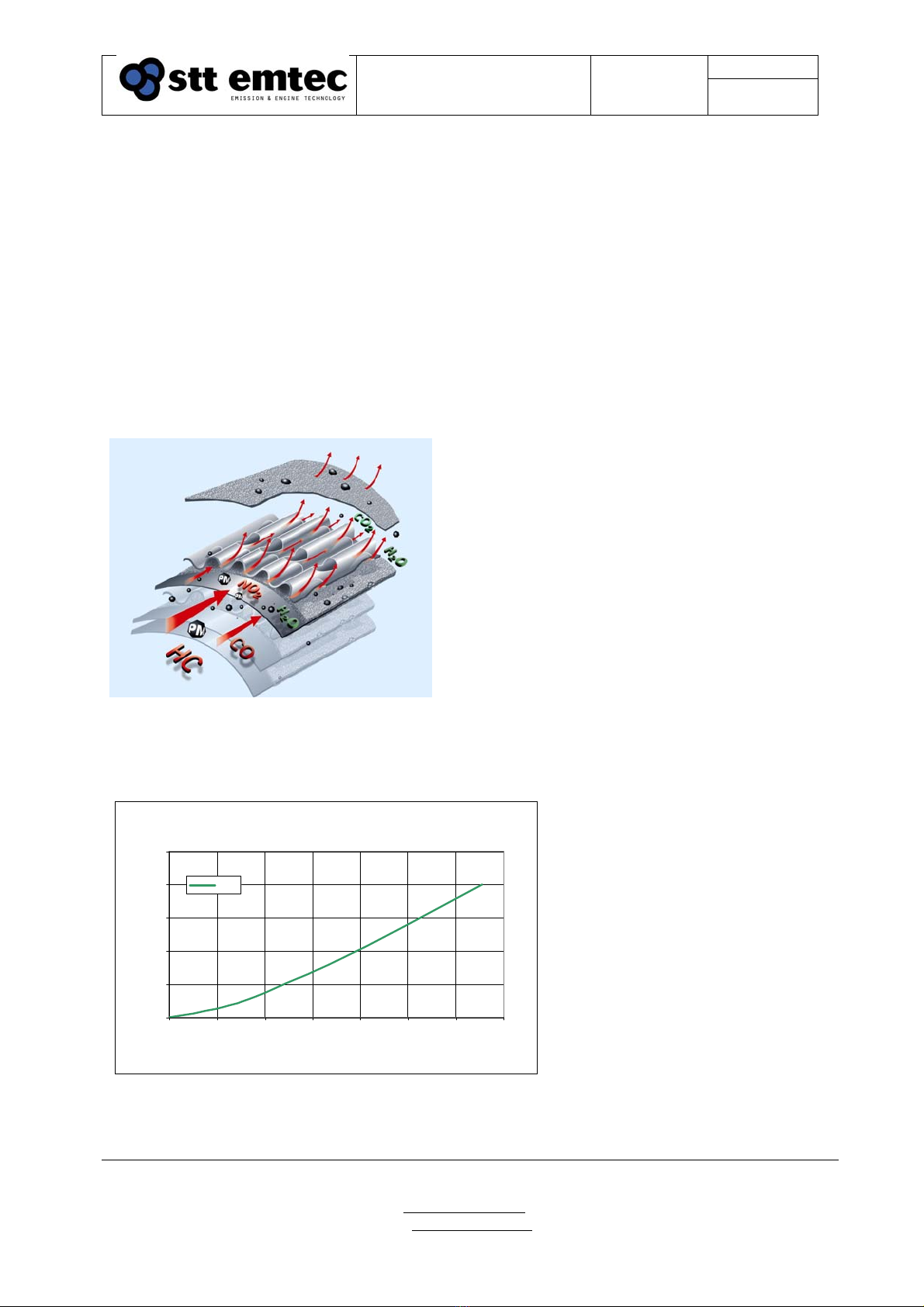
The POC works with a wall-flow and partial flow principle, which guarantees trouble free engine
operation even without regenerations. The separated particles are reduced by a continuous reaction
with NO2.
Figure 9. (Picture from Emitec)
Exploded view of the POC
It is maintenance free and has a quite low affect on the backpressure. The figure 10 below shows
the backpressure in a stand alone application.
0
20
40
60
80
100
0 1000 2000 3000 4000 5000 6000 7000
Actual Exhaust Volume Flow (M3/h)
Pressure drop (mbar)
POC
Figure 10.
Page 11Document
STT SCRmarine
Installation Guideline
Date
2014-08-27 Issue: 1.6
STT Emtec AB (pbl)
Kontorsvägen 9
SE-852 29 SUNDSVALL
SWEDEN
Tel: +46 (0)60-64 10 40
Fax: +46 (0)60 64 10 45
e-mail: info@sttemtec.com
Internet: www.sttemtec.com
Head office: Sundsvall
Org.nr: 55 62 05 – 2927
VAT ID: SE556205292701
ISO-cetrifikat nr: 15627
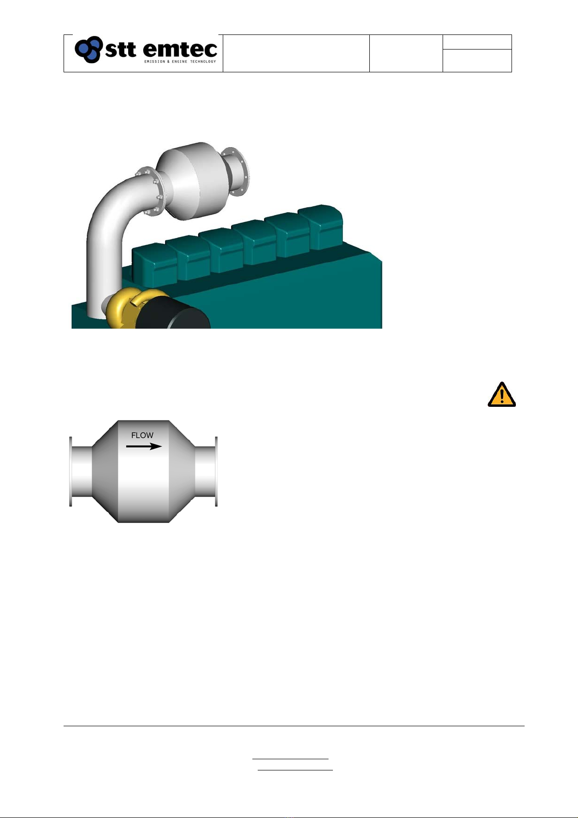
The POC must be installed as close as possible to the turbocharger outlet, the exhaustpipe and
POC must be insulated in order to keep the exhaust temperature as high as possible when it enters
the POC, but also to ensure the engine crew safety and protection of the surrounding areas.
Figure 11.
POC installed close to the turbocharger outlet.
Note! The flow direction arrow must be pointing with the exhaust flow.
Figure 12.
Flow direction arrow on the POC.
Data
Material, canning: Stainless steel AISI 316/316L, AISI 304/304L
Dimensions: L=599 ±3mm
D=416 mm
Inlet/outlet port: Flanges for DN125, DN150 and DN200 exhaust pipe.
Maintenance: No maintenance required, check for exhaust leaks at the
same time as the rest of the exhaust system.

Page 12Document
STT SCRmarine
Installation Guideline
Date
2014-08-27 Issue: 1.6
STT Emtec AB (pbl)
Kontorsvägen 9
SE-852 29 SUNDSVALL
SWEDEN
Tel: +46 (0)60-64 10 40
Fax: +46 (0)60 64 10 45
e-mail: info@sttemtec.com
Internet: www.sttemtec.com
Head office: Sundsvall
Org.nr: 55 62 05 – 2927
VAT ID: SE556205292701
ISO-cetrifikat nr: 15627
2.2.3 Noise reduction
The SCR catalysts system will contribute to the total exhaust system noise reduction.
The noise attenuation for a SCR system without the POC option will be between 10 and 15 dB(A)
and in combination with a POC the attenuation can be up to 20 dB(A).
Note that these values are guidelines only and the total noise attenuation of the complete exhaust
system is the responsibility of the installer or the supplier of the exhaust system.
2.2.4 Catalyst
The catalysts are designed by the same principle, regardless of content. The canning is produced
of stainless steel with flanges on the in- and outlet ports. The shape of the flanges can differ due to
regulations and/or customer demands. The flange pairs are mounted with a 1.5mm stainless steel
reinforced graphite gasket.
Additional brackets to support the catalyst assembly are required due to the weight of the catalyst.
The design of the support may be depending on the surroundings and support of other parts. STT
Emtec recommends the use of metal resilient elements type Vibratec® or similar.
Welding is not allowed on the catalyst in the red area marked in figure 13. The catalyst contains
sliding parts for heat elongation handling which can be damaged by welding.
The exhaust pipes between the engine and SCR catalyst, the SCR mixer and the SCR catalyst itself
must be insulated. The purpose of the insulation is to retain required operating exhaust
temperature for the SCR catalyst at low load conditions and cold ambient temperatures. It is also
necessary to keep the surface temperature of the pipes and SCR mixer at a level where condense is
avoided. Additional insulation may be used according to regulations and/or customer demands. It
is important to leave space for the insulation at the installation. In a typical installation the
insulation is minimum 50 mm thick.
Figure 13.
Catalyst assembly. The red area shows where welding is not allowed.
Page 13Document
STT SCRmarine
Installation Guideline
Date
2014-08-27 Issue: 1.6
STT Emtec AB (pbl)
Kontorsvägen 9
SE-852 29 SUNDSVALL
SWEDEN
Tel: +46 (0)60-64 10 40
Fax: +46 (0)60 64 10 45
e-mail: info@sttemtec.com
Internet: www.sttemtec.com
Head office: Sundsvall
Org.nr: 55 62 05 – 2927
VAT ID: SE556205292701
ISO-cetrifikat nr: 15627
2.2.5 Thermal expansion
Relative movements and heat extension must always be considered when routing and installing
exhaust pipes. Use gastight flexible parts and compensators when necessary.
In general a heat expansion of 1-2 mm /meter piping for every 100°C can be used as a rule of
thumb.
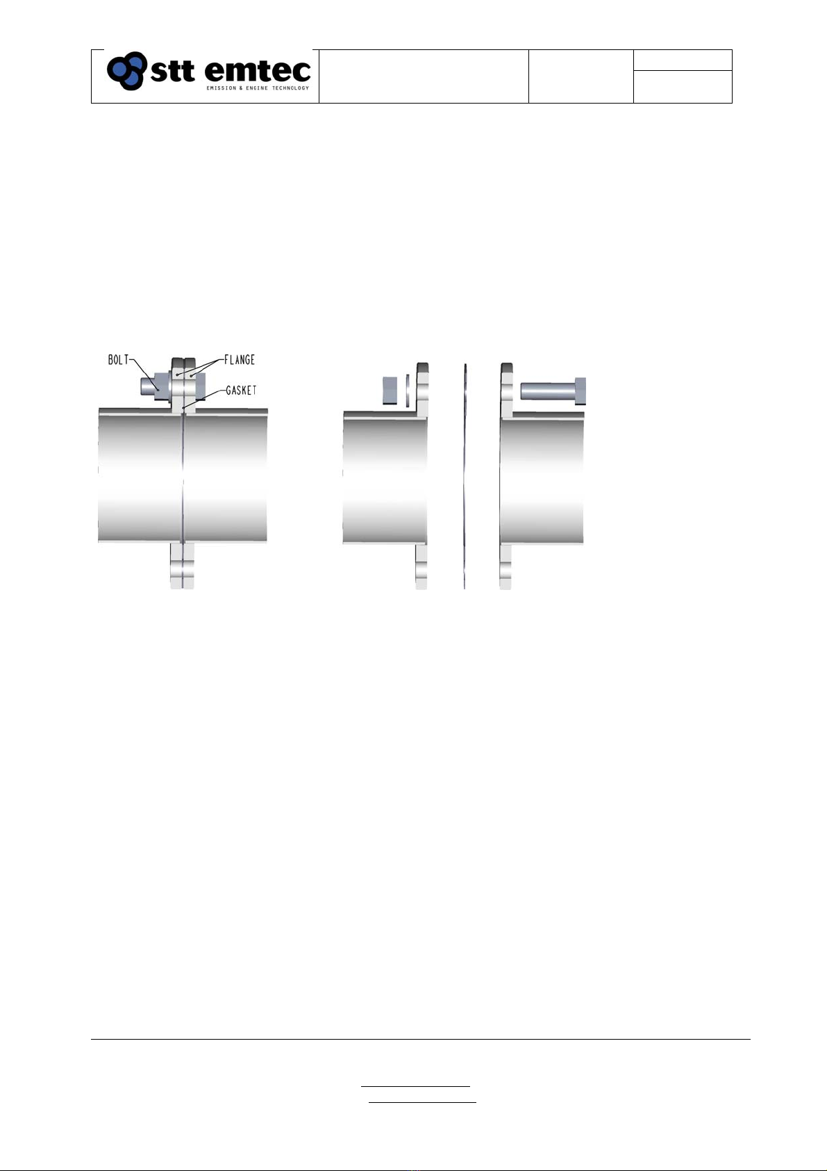
Flanges are welded on the pipe ends. The flange pairs are mounted together with a 1.5mm
stainless steel reinforced graphite gasket. For attachment, 8 - 16 pcs of zinc plated screws (or
stainless) M16x60 8.8 with nuts and washers are used. The shape of the flanges can differ due to
regulations and/or customer demands.
Figure 14. Figure 15.
Flange pair Flange pair (exploded view)
Page 14Document
STT SCRmarine
Installation Guideline
Date
2014-08-27 Issue: 1.6
STT Emtec AB (pbl)
Kontorsvägen 9
SE-852 29 SUNDSVALL
SWEDEN
Tel: +46 (0)60-64 10 40
Fax: +46 (0)60 64 10 45
e-mail: info@sttemtec.com
Internet: www.sttemtec.com
Head office: Sundsvall
Org.nr: 55 62 05 – 2927
VAT ID: SE556205292701
ISO-cetrifikat nr: 15627
2.3 Mixer assembly & injection nozzle
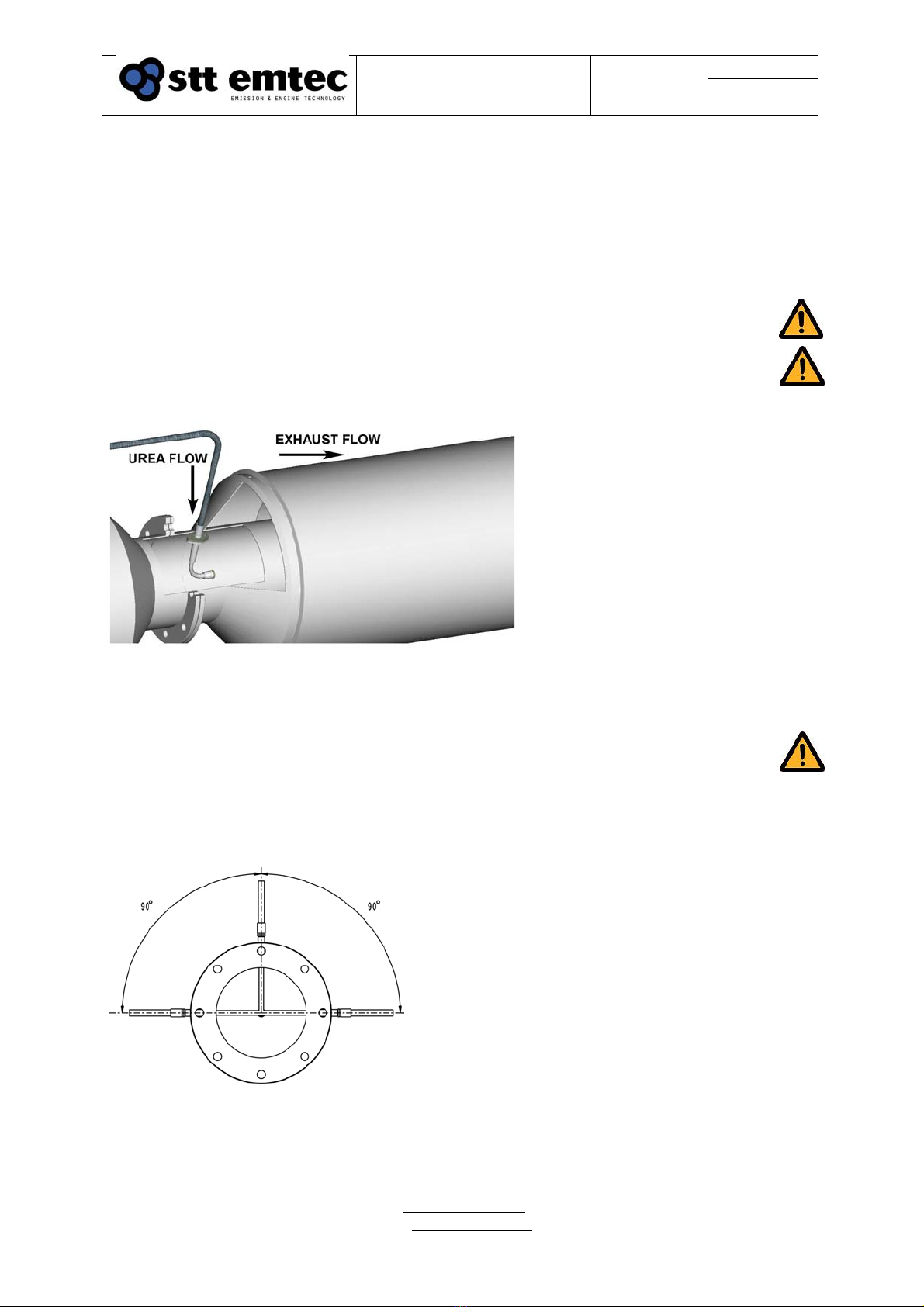
The mixer assembly, see figure 16 below is a part of the exhaust system and contains the injection
nozzle. The urea is mixed with compressed air in the urea pump and is transported to the nozzle
and into the exhaust flow. With guidance from the exhaust flow and the mixer wings, a swirl is
created and an even distribution over the SCR catalyst is obtained.
The nozzle can be bent to make a proper route from the manifold to the mixer unit.
Note! The inside radius of the hose must not be bent narrower than 125mm.
Note! In case of a vertical stack, there must be a water trap installed between the
injection point and the engine.
Figure 16.
Mixer assembly, cross section
Note! It is important that the nozzle tip is oriented in the same direction as the
exhaust flow. When the mixer is mounted in a horizontal position the orientation
of the nozzle must be on the topside of the mixer not more than ± 90° from the
vertical plane. See figure 17 below.
Figure 17.
Nozzle installation, allowed angle
Page 15Document
STT SCRmarine
Installation Guideline
Date
2014-08-27 Issue: 1.6
STT Emtec AB (pbl)
Kontorsvägen 9
SE-852 29 SUNDSVALL
SWEDEN
Tel: +46 (0)60-64 10 40
Fax: +46 (0)60 64 10 45
e-mail: info@sttemtec.com
Internet: www.sttemtec.com
Head office: Sundsvall
Org.nr: 55 62 05 – 2927
VAT ID: SE556205292701
ISO-cetrifikat nr: 15627
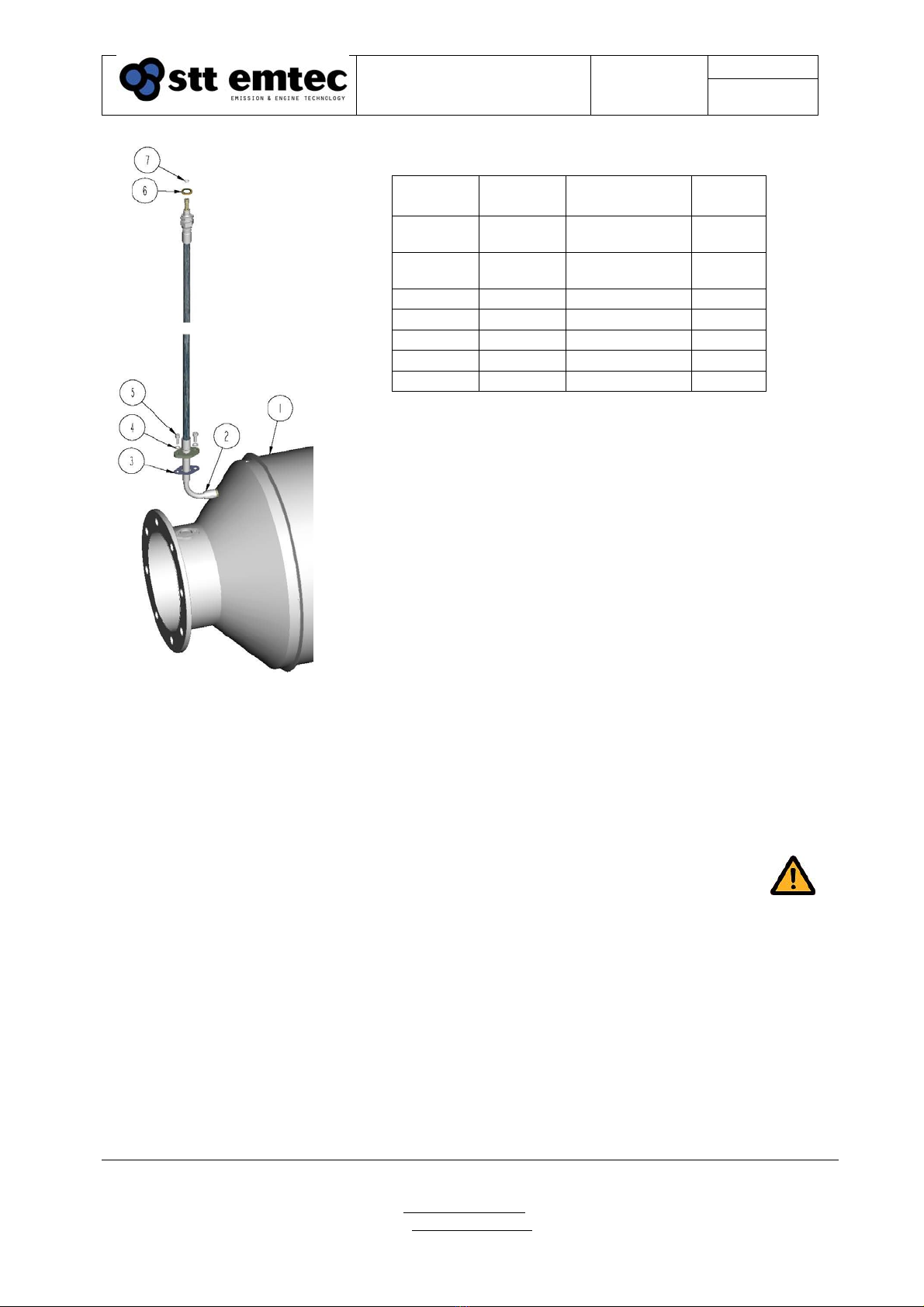
Figure 18. Mixer assembly with injection nozzle
1. Mixer assembly, 2. Injection nozzle, 3. Gasket, 4. Washer, 5. Screw, 6. Sealing, 7. O-ring
2.3.1 Replacing the injection nozzle
Note! Start by releasing the air pressure and make sure that the system is
powerless. If the nozzle is blocked /clogged, note that pressurized air can be
trapped in the urea line from the pump to the nozzle!
The gasket, screws, sealing and o-ring (pos 3-7 above) can be reused if the condition of the
components are acceptable. The gasket shall always be replaced. When installing the new nozzle,
check that that the nozzle tip is oriented in the same direction as the exhaust flow, see figure 16
above.
Pos P/N Description Quantity
01 Application
specific Mixer Housing 1
02 Application
specific Injection Nozzle 1
03 102273 Gasket 1
04 104090 Washer, spring 2
05 104089 Screw 2
06 102270 Washer, Tredo 1
07 102283 O-ring 1
Page 16Document
STT SCRmarine
Installation Guideline
Date
2014-08-27 Issue: 1.6
STT Emtec AB (pbl)
Kontorsvägen 9
SE-852 29 SUNDSVALL
SWEDEN
Tel: +46 (0)60-64 10 40
Fax: +46 (0)60 64 10 45
e-mail: info@sttemtec.com
Internet: www.sttemtec.com
Head office: Sundsvall
Org.nr: 55 62 05 – 2927
VAT ID: SE556205292701
ISO-cetrifikat nr: 15627
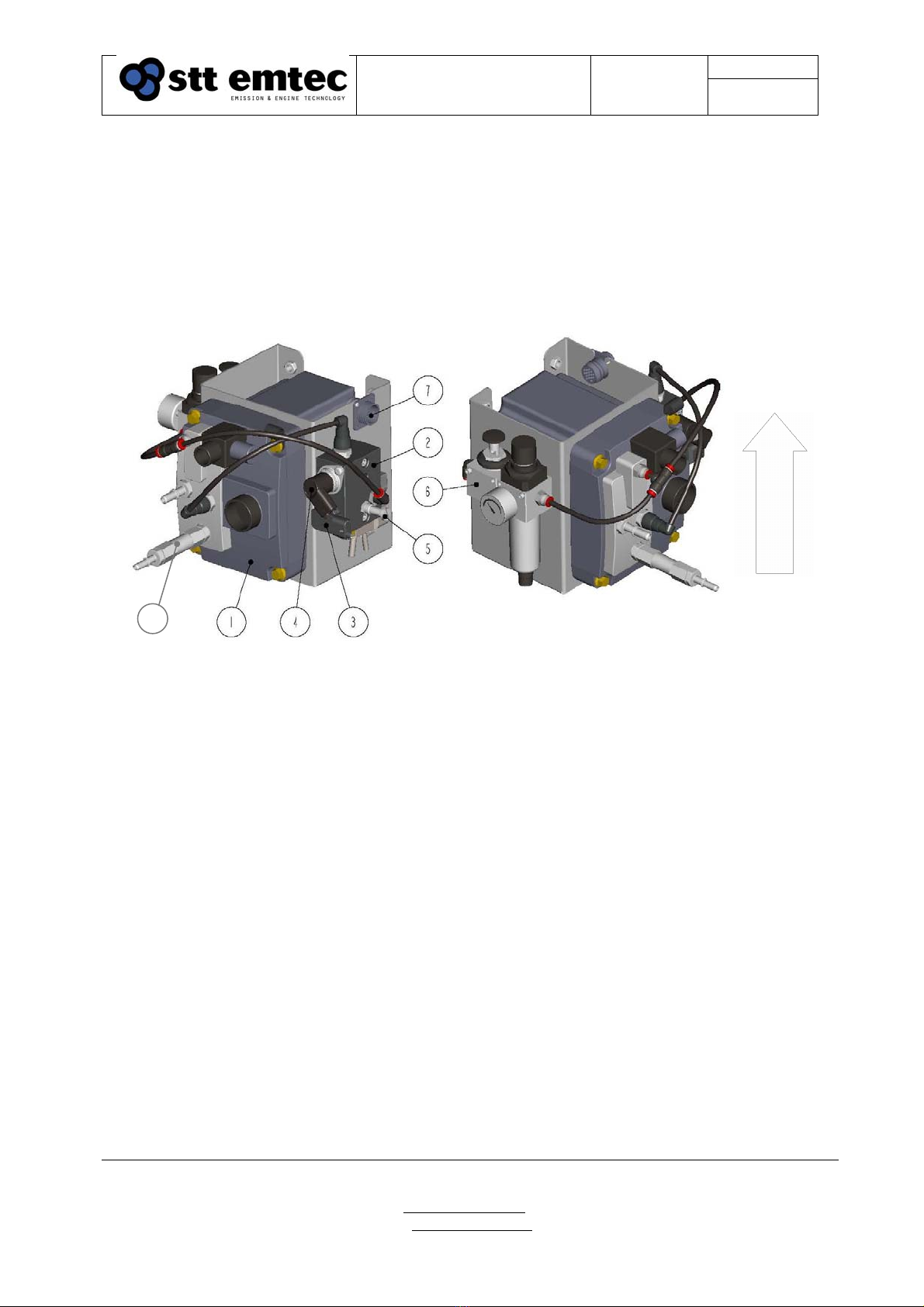
2.4 Urea Dosing Unit (UDS)
The urea dosing unit consists of urea pump, manifold for urea/air, air pressure sensor, urea
pressure sensor and a FRL-unit (Filter-Regulator-Lubricator). It is designed to supply the nozzle
with urea. Pressurized air is used to create a fine mist of urea to enable an even distribution over
the catalyst surface. The urea dosing is done by the built-in diaphragm pump. A heater is installed
in the pump unit to allow the system to operate at low temperatures. The urea pump is controlled
by the electronic control unit (ECU).
Figure 19. Urea dosing unit (UDS)
1. Urea pump, 2. Urea/air dosing manifold, 3. Air pressure sensor, 4. Urea pressure sensor, 5. Secondary air
pressure regulator, 6. Main air pressure regulator, 7. Main connector, 8. DEF filter
2.4.1 Installation
For proper function, the urea pump and its components should be oriented, as shown in figure 19
above.
The urea dosing unit is mounted with flanged screws on an additional bracket. This bracket has to
be attached to a fixed point in the engine room either on the bottom or its back. In case of heavy
vibrations, additional rubber bobbins should be used (STT P/N 101793).
UP
8

Page 17Document
STT SCRmarine
Installation Guideline
Date
2014-08-27 Issue: 1.6
STT Emtec AB (pbl)
Kontorsvägen 9
SE-852 29 SUNDSVALL
SWEDEN
Tel: +46 (0)60-64 10 40
Fax: +46 (0)60 64 10 45
e-mail: info@sttemtec.com
Internet: www.sttemtec.com
Head office: Sundsvall
Org.nr: 55 62 05 – 2927
VAT ID: SE556205292701
ISO-cetrifikat nr: 15627
Figure 20.
Bracket for urea dosing unit
Figure 21. Figure 22.
UDS with additional rubber bobbins UDS bracket with rubber bobbins (cross section)
2.4.2 Replacing the urea dosing unit
Note! Start by releasing the air pressure and make sure that the system is
powerless. If the nozzle is blocked /clogged, note that pressurized air can be
trapped in the urea line from the pump to the nozzle!
Note! When releasing the urea- and the electric connections, make sure no urea
gets in contact with the connector receptacles!
View from rear View from bottom
Page 18Document
STT SCRmarine
Installation Guideline
Date
2014-08-27 Issue: 1.6
STT Emtec AB (pbl)
Kontorsvägen 9
SE-852 29 SUNDSVALL
SWEDEN
Tel: +46 (0)60-64 10 40
Fax: +46 (0)60 64 10 45
e-mail: info@sttemtec.com
Internet: www.sttemtec.com
Head office: Sundsvall
Org.nr: 55 62 05 – 2927
VAT ID: SE556205292701
ISO-cetrifikat nr: 15627
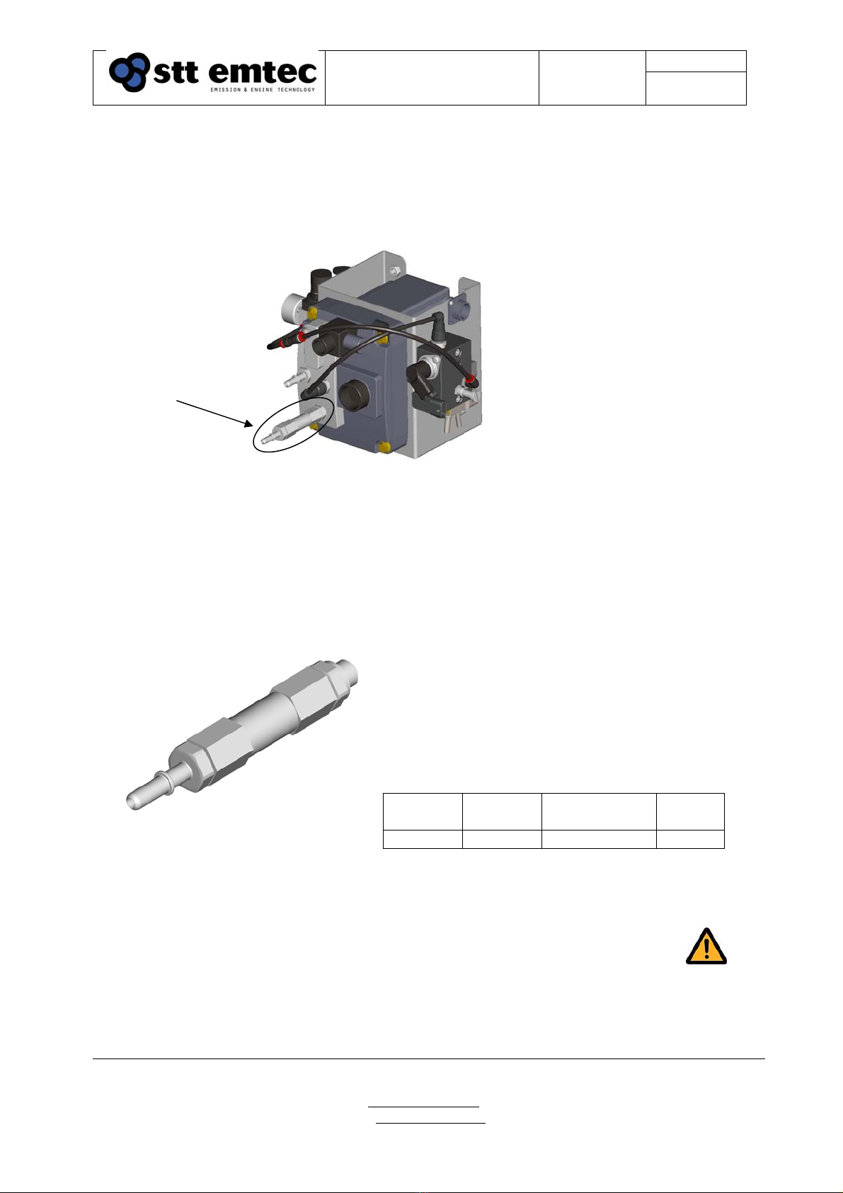
2.4.3 Replacing the DEF filter
The urea dosing unit is equipped with an in-line DEF (urea) filter to prevent particulates from
entering the dosing system and interrupting the dosing function.
The filter unit consists of a filter body, filter element and the hose fitting
Figure 23.
DEF filter location
To replace the DEF filter unit make sure that the system is powerless. Disconnect the urea suction
hose from the fitting on the filter unit. Unscrew the entire filter unit from the pump. Fit the new
filter unit (new O-ring sealing included) and reconnect the urea hose before turning power back
on.
Figure 24.
DEF filter unit
The filter unit shall be replaced every 12 mon.
Pos P/N Description Quantity
01 108930 DEF filter unit 1
DEF filter
Page 19Document
STT SCRmarine
Installation Guideline
Date
2014-08-27 Issue: 1.6
STT Emtec AB (pbl)
Kontorsvägen 9
SE-852 29 SUNDSVALL
SWEDEN
Tel: +46 (0)60-64 10 40
Fax: +46 (0)60 64 10 45
e-mail: info@sttemtec.com
Internet: www.sttemtec.com
Head office: Sundsvall
Org.nr: 55 62 05 – 2927
VAT ID: SE556205292701
ISO-cetrifikat nr: 15627
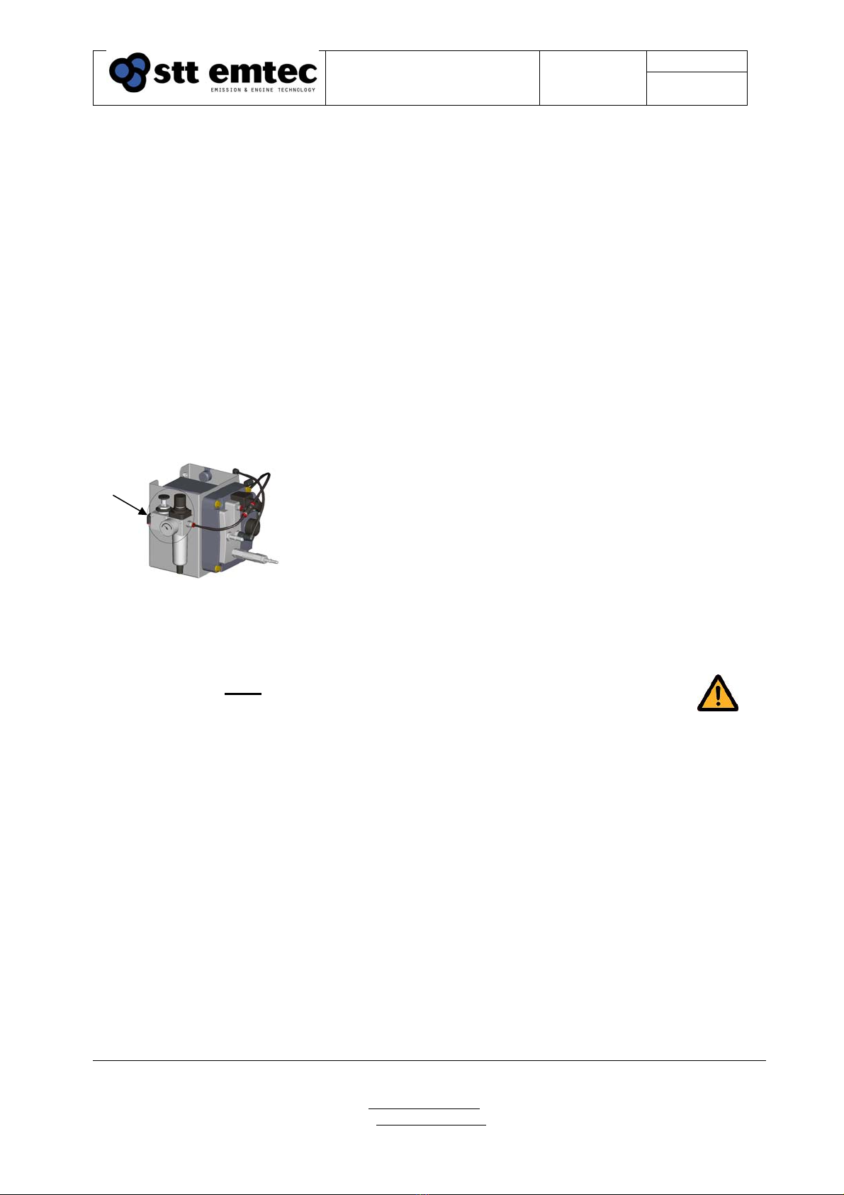
2.4.4 Adjusting the main air pressure
The main air pressure regulator is located on the left hand side of the urea dosing unit. The
regulator is connected to the vehicle air pressure or an additional air compressor. Max allowed
inlet pressure is 12 bar and has to be adjusted to 5.5±0.5 bar. Use the manometer on the FRL-unit
when adjusting the air pressure.
Use the Diagnostic tool (software) to verify the main air pressure;
Start the Diagnostic tool and connect to the Electronic Control Unit (ECU) (see Diagnostic tool
manual in Appendix 4). Release the main air pressure by clicking the control button “UDS air” in
the System tab and make sure that the meter “Air valve” shows “ON”. (When the engine is
running, or has just been stopped, the air valve is already “ON”) The meter “Nozzle prs” shall
read 1600±200 mbar when correct air pressure is adjusted. This reading is in gauge i.e. showing ≈
0±200 mbar when the air valve is “OFF”
Figure 25.
Main air pressure regulator on FRL-unit
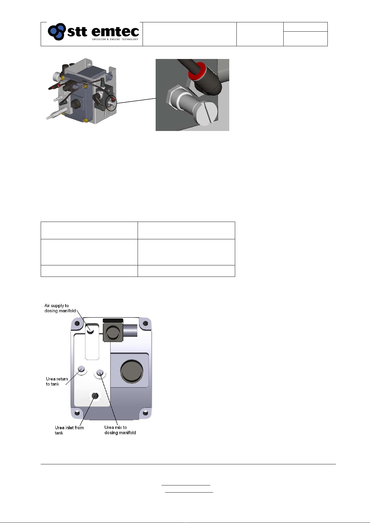
2.4.5 Adjusting secondary air pressure
Note! Adjust the main air pressure as described in 2.4.3 before adjusting the
secondary air pressure!
The secondary air pressure regulator is located on the right hand side of the manifold on the urea
dosing unit. When the main air pressure is set to 5.5±0.5 bar, use the Diagnostic tool (software) to
adjust the secondary air pressure.
The procedure using the Diagnostic tool is as follows; start the Diagnostic tool and connect to the
Electronic control unit (ECU) (see the Diagnostic tool manual in appendix 4). Release the air
pressure by clicking the control button on the screen named “Mantle Air”. (When the engine is
running, or has just been stopped, the air valve is already “ON”) To adjust the air pressure, use the
adjustable pressure regulator shown in figure 26 below. On the screen a meter named “Mantle prs
(mbar)” should read 1800±200 mbar when correct air pressure is adjusted. This reading is in
absolute i.e. showing ≈1000±200 mbar when the air valve is “OFF”
Use the locking device to secure the adjustment screw.
Page 20Document
STT SCRmarine
Installation Guideline
Date
2014-08-27 Issue: 1.6
STT Emtec AB (pbl)
Kontorsvägen 9
SE-852 29 SUNDSVALL
SWEDEN
Tel: +46 (0)60-64 10 40
Fax: +46 (0)60 64 10 45
e-mail: info@sttemtec.com
Internet: www.sttemtec.com
Head office: Sundsvall
Org.nr: 55 62 05 – 2927
VAT ID: SE556205292701
ISO-cetrifikat nr: 15627
Figure 26.
Secondary air pressure regulator
Compressed air should be provided from the ships air supply with installed oil separator. If the
compressed air supply includes an air dryer, then if possible, take the air supply to the urea pump
before the air dryer. If a compressed air system is not available a separate air compressor has to be
installed.
Table 1 below contains STT Emtec’s recommendations of the air compressor.
Table 1: Compressor data recommendations
Capacities Min 20 l/min at 6 bar absolute
pressure (100 l/min FAD)
Tank volume Min 150 l to reduce the
number of compressor start
up
Standard pressures 6-12 bar
2.5 Urea/air lines & connections
Figure 27.
Port interface
Other manuals for SCRmarine
1
Table of contents


