schweisskraft EASY-MIG 201 i MULTI User manual

EASY-MIG 201i MULTI
Operating Instructions
EASY-MIG 201i MULTI
MIG/MAG Inverter
EASY-MIG 211i MULTI
EASY-MIG 211i MULTI

2EASY-MIG | Version 1.04
Imprint
Product identification
MIG/MAG Inverter Item number
EASY-MIG 201i MULTI 1089020
EASY-MIG 211i MULTI 1089021
Manufacturer
Stürmer Maschinen GmbH
Dr.-Robert-Pfleger-Str. 26
D-96103 Hallstadt
Fax: 0049 (0) 951 - 96555-55
E-Mail: [email protected]
Internet: www.schweisskraft.de
Indications regarding the operating instructions
Original instructions
according to DIN EN ISO 20607:2019
Edition: 18.07.2022
Version: 1.04
Language: English
Author: MS/ES
Indications regarding the copyright
Copyright © 2022 Stürmer Maschinen GmbH, Hallstadt,
Germany.
Subject to technical modifications and error.
Content
1 Introduction ............................................. 3
1.1 Copyright ............................................................ 3
1.2 Customer service................................................ 3
1.3 Limitation of liability............................................. 3
2 Safety ....................................................... 3
2.1 Symbol explanation ............................................ 3
2.2 Obligations of the operating company ................ 4
2.3 Requirements to staff.......................................... 4
2.4 Personal protective equipment ........................... 5
2.5 General safety instructions ................................. 5
2.6 Safety labels ....................................................... 7
2.7 Safety data sheets .............................................. 7
2.8 Safety devices .................................................... 7
3 Intended use............................................ 7
3.1 Reasonably foreseeable misapplication ............. 8
3.2 Residual risks ..................................................... 8
4 Technical Data......................................... 8
4.1 Type plate ........................................................... 9
5 Transport, packaging, storage............... 9
5.1 Delivery and transport......................................... 9
5.2 Packaging........................................................... 9
5.3 Storage ............................................................... 9
6 Principle of operation ............................. 9
6.1 Principle of the metal inert gas welding process.. 10
6.2 Functional principle of wire feeding .................. 10
6.3 Torch equipment............................................... 10
7 Operation ............................................... 11
7.1 Description of device ........................................ 11
7.2 Scope of delivery .............................................. 13
7.3 Installation conditions ....................................... 13
7.4 Electrical connection......................................... 13
7.5 Welding circuit connections .............................. 13
7.6 Inserting the welding rod reel and wire guide ... 14
7.7 Weld preparation .............................................. 15
7.8 Welding............................................................. 16
7.9 Description and use of different arc types ........ 18
7.10 Selection of wire electrode and inert gas...... 18
8 Maintenance .......................................... 18
8.1 Regular maintenance........................................ 18
8.2 Special maintenance ........................................ 19
9 Troubleshooting.................................... 19
10 Disposal, Recycling of old equipment... 21
10.1 Decommission ............................................... 21
10.2 Disposal of electrical equipment.................... 21
10.3 Disposal via municipal collection points......... 21
11 Spare parts ....................................... 21
11.1 Spare parts order........................................... 21
11.2 Spare parts drawings..................................... 22
12 Electrical circuit diagrams ................. 24
13 EC Declaration of Conformity ............ 26
14 Notes .................................................... 27

EASY-MIG | Version 1.04 3
Introduction
1 Introduction
You have made a good choice by purchasing the
SCHWEISSKRAFT MIG/MAG inverter welder.
Read the operating instructions carefully before
commissioning.
This is an important part and must be kept near the ma-
chine and accessible to every user.
The operating manual informs you about the proper
start-up, the intended use as well as the safe and effi-
cient operation and maintenance of the MIG/MAG inver-
ter welder.
In addition, observe the local accident prevention regula-
tions and general safety regulations for the area of appli-
cation of the MIG/MAG inverter welder.
1.1 Copyright
The contents of these instructions are protected by copy-
right and are the sole property of Stürmer Maschinen
GmbH. Their use is permitted within the scope of the use
of the MIG/MAG inverter welder. Any other use is not
permitted without the written approval of the manufactu-
rer.
Passing on as well as duplication of this document, utili-
zation and communication of its contents are prohibited,
unless expressly permitted. Violations will result in liabi-
lity for damages. We register trademark, patent and de-
sign rights for the protection of our products, if this is
possible in individual cases. We emphatically oppose
any infringement of our intellectual property.
1.2 Customer service
If you have any questions about your device or technical
information, please contact your dealer. There you will
be happy to help with expert advice and information.
Germany:
Stürmer Maschinen GmbH
Dr.-Robert-Pfleger-Str. 26
D-96103 Hallstadt
Repair-Service:
Fax: 0049 (0) 951 96555-111
Email: service@stuermer-maschinen.de
Spare parts orders:
Fax: 0049 (0) 951 96555-119
Email: ersatzteile@stuermer-maschinen.de
We are always interested in information and experiences
that arise from the application and can be valuable for
the improvement of our products.
1.3 Limitation of liability
All information and instructions in the operating instructi-
ons have been compiled taking into account the applica-
ble standards and regulations, the state of the art as well
as our many years of knowledge and experience. In the
following cases, the manufacturer assumes no liability
for damages:
- Failure to observe the operating instructions,
- Improper use,
- Use of untrained personnel,
- Unauthorized conversions,
- Technical changes,
- Use of unauthorized spare parts.
The actual scope of delivery may differ from the explana-
tions and illustrations described here for special versi-
ons, when using additional order options or due to the la-
test technical changes.
The obligations agreed in the delivery contract, the gene-
ral terms and conditions as well as the delivery conditi-
ons of the manufacturer and the legal regulations valid at
the time of the conclusion of the contract apply.
2 Safety
This section provides an overview of all major safety
packages for personal protection and safe and trouble-
free operation. Further task-related safety instructions
are contained in the individual chapters.
2.1 Symbol explanation
Safety instructions
Safety instructions are indicated by symbols in these
operating instructions. The safety instructions are in-
itiated by signal words that express the extent of the ha-
zard.

4EASY-MIG | Version 1.04
Safety
Tips and recommendations
To reduce the risk of personal injury and property da-
mage and to avoid dangerous situations, the safety in-
structions in this manual must be observed.
2.2 Obligations of the operating com-
pany
The operating company is the person who operates the
welding device for business or commercial reasons by
herself, or leaves it to a third party for use or application,
and who bears the legal product responsibility for the
protection of the user, the staff or for third parties.
Obligations of the operating company
If the welding device is used for commercial purposes,
the operating company of the welding device must com-
ply with the legal working safety regulations.
Therefore, the safety notes in this operating manual, as
well as the safety, accident prevention and environment
protection regulations applying for the area of application
of the welding device must be met. The following applies
in particular:
- The operating company must be informed about the
applying industrial safety regulations and further an-
alyse hazards resulting from the special working
conditions at the place of use of the welding device.
She must implement these in form of operating man-
uals for the operation of the welding device.
- During the entire lifetime the welding device, the
operating company must verify whether the operat-
ing manuals prepared by her correspond to the
current status of the regulations, and must adapt
these if necessary.
- The operating company must unambiguously regu-
late and determine the responsibilities for installa-
tion, operation, troubleshooting, maintenance and
cleaning.
- The operating company must ensure that all per-
sons who work with the welding device, have read
and understood this manual. Furthermore she
must instruct the staff in regular intervals and in-
form them about the hazards.
- The operator must provide the necessary protec-
tive equipment to the staff and order the use of the
necessary protective equipment in a binding way.
Furthermore the operating company is responsible to
keep the welding device always in a technically flawless
state. Thus, the following applies:
- The operator must ensure that the maintenance in-
tervals described in this manual are kept.
- The operator must have all safety devices checked
regularly for their good working order and their in-
tegrity.
2.3 Requirements to staff
Qualifications
The different tasks described in this manual represent
different requirements to the qualification of the persons
entrusted with these tasks.
DANGER!
This combination of symbol and signal word indicates
an immediately dangerous situation. It leads to death
or serious injury if it is not avoided.
WARNING!
This combination of symbol and signal word indicates a
potentially dangerous situation. It leads to death or serious
injury if it is not avoided.
CAUTION!
This combination of symbol and signal word indicates
a potentially dangerous situation. It can cause minor
or minor injuries if not avoided.
ATTENTION!
This combination of symbol and signal words indi-
cates a possibly dangerous situation which may lead
to property and environmental damages if they are
not avoided.
NOTE!
This combination of symbol and signal word indicates
a potentially dangerous situation. It can lead to mate-
rial and environmental damage if it is not avoided.
Tips and recommendations
This symbol highlights useful tips and recommendati-
ons as well as information for efficient and trouble-
free operation.

EASY-MIG | Version 1.04 5
Safety
Only persons reliable working procedures can be ex-
pected from, are allowed to perform all works. Persons
the responsiveness of which is affected by e. g. drugs,
alcohol or medication, are not allowed to work with the
machine.
The qualifications of the personnel for the different tasks
are mentioned below:
Operator
The operator is instructed by the operating company
about the assigned tasks and possible risks in case of
improper behaviour. Any tasks which need to be per-
formed beyond the operation in the standard mode must
only be performed by the operator if it is indicated in
these instructions and if the operating company expres-
sively commissioned the operator.
Electrically qualified person
Electrically qualified person is due to their professional
training, knowledge and experience as well as knowl-
edge of the relevant standards and regulations, in a posi-
tion to carry out work on the electrical systems and to in-
dependently recognize and avoid possible dangers.
Qualified personnel
Due to their professional training, knowledge and experi-
ence as well as their knowledge of relevant regulations
the specialist staff is able to perform the assigned tasks
and to recognise and avoid any possible dangers them-
selves.
Manufacturer
Certain works may only be performed by specialist per-
sonnel of the manufacturer. Other personnel is not au-
thorized to perform these works. Please contact our cus-
tomer service for the execution of all arising work.
2.4 Personal protective equipment
The personal protective equipment serves to protect per-
sons against impairments of safety and health while
working. The staff member has to wear personal protec-
tive equipment while performing different tasks on and
with the machine which are indicated in the individual
paragraphs of these instructions.
The personal protective equipment is explained in the
following paragraph:
2.5 General safety instructions
Please note the following:
- The operator must be sufficiently trained in the safe
use of the welding device. The operator must be in-
formed about the risks involved in arc welding proce-
dures, about the protective precautions and the be-
haviour in an emergency. (See also standard "EN
60974-9: Arc welding equipment". Part 9: Erection
and operation").
- Avoid direct contact with the welding circuit; the
open-circuit voltage provided by the welding ma-
chine is dangerous under certain conditions.
- The connection of welding cables, tests and repairs
may only be carried out when the welding device
has been switched off and disconnected from the
power supply.
- Switch off the welding unit and disconnect the power
plug as soon as you replace operating materials or
wearing parts.
WARNING!
Danger in case of insufficient quali-
fication of the staff!
Insufficiently qualified persons cannot estimate the
risks while using the welding device and expose
themselves and others to the danger of severe or
lethal injuries.
- Have all works only performed by qualified persons.
- Keep insufficiently qualified persons out of the work-
ing area.
Welders face protection shield or
helmet with welder's face protec-
tion shield
The welding shield, which is wear on the head and in
front of the face or is attached to a suitable protec-
tive helmet, protects eyes and face, equipped with
suitable filters.
Protective gloves with pulse pro-
tection
The protective gloves with pulse protection protect
hands from sharp-edged components as well as from
friction, abrasions, minor burns or deeper injuries.
Safety boots
Safety boots protect the feet from being crushed, fall-
ing parts and slipping over on slippery ground.
Protective clothes
Protective clothes are made of a tightly fitted fabric
without the protruding parts of low tear strength.
Protective apron
The protective apron mainly protects the front of the
body against sparks or radiation during welding.

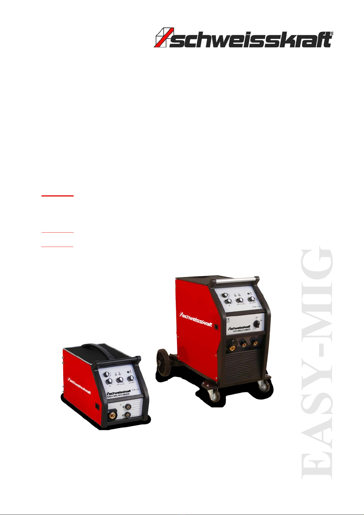
6EASY-MIG | Version 1.04
Safety
- Before replacing wearing parts of the torch, the wel-
ding device must be switched off and disconnected
from the mains supply.
- The electrical installation must be carried out in ac-
cordance with the relevant regulations and accident
prevention regulations.
- The welding unit may only be connected to a supply
network with earthed neutral conductor.
- Make sure that the current socket is correctly
connected to the protective earth.
- The welding device must not be used in a damp or
wet environment or in rain.
- Do not use cables with worn insulation or loose
connections - If a liquid cooling unit is available, it
must only be filled when the welding unit is switched
off and disconnected from the mains.
- Do not weld on containers, vessels or pipes that con-
tain or have contained flammable liquids or gases.
- Do not work on materials that have been cleaned
with chlorinated solvents. Do not work near these
solvents.
- Do not weld on pressurized containers.
- Remove all flammable substances (e.g. wood, pa-
per, scraps of fabric, etc.).
- Ensure that there is sufficient air exchange or
suitable aids to dissipate the flue gases released du-
ring welding near the arc. It must be systematically
examined which limit values apply to the respective
composition, concentration and exposure time of the
welding exhaust gases.
- The gas cylinder must be protected from heat sour-
ces including solar radiation.
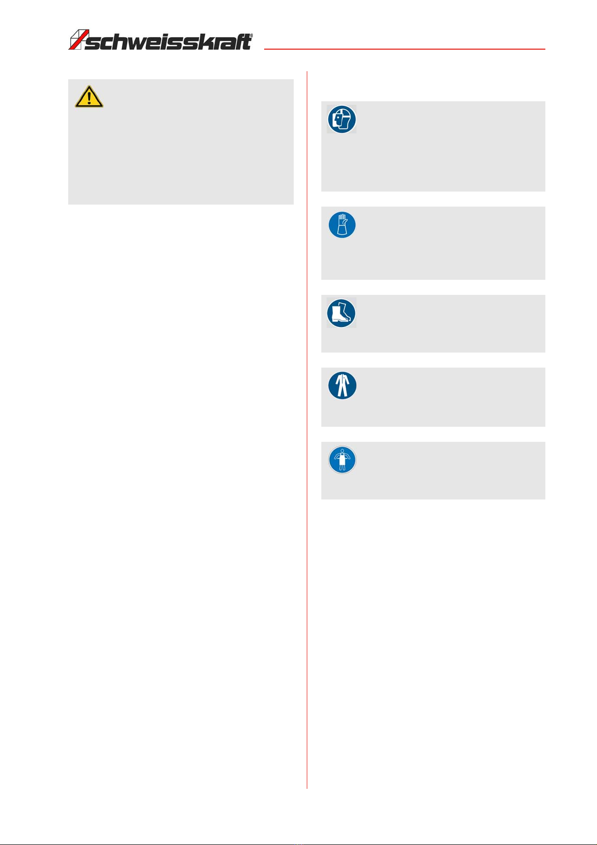
- Ensure proper electrical insulation of the electrode,
the workpiece and nearby (accessible) earthed me-
tal parts. It is normally sufficient to wear appropriate
gloves, footwear, headgear and clothing, as well as
footboards and insulating carpets.
- Always protect your eyes with glare glass attached
to masks or helmets. Use appropriate fire-retardant
protective clothing and avoid exposing the skin to
UV and infrared radiation from the arc, and use um-
brellas or non-reflecting curtains to protect third par-
ties near the arc.
- Noise: If a daily level of 85 db(A) or more (LEPd) is rea-
ched during particularly intensive welding work, appro-
priate individual protective equipment must be used.
- When the welding current passes, electromagnetic
fields (EMF) are generated in the vicinity of the wel-
ding current circuit. The electromagnetic fields can
impair medical aids (e.g. pacemakers, breathing
aids or metal prostheses). Appropriate protective
measures must be taken for the wearers of these
aids, for example by prohibiting them from entering
the operating area of the welding device.
- This welding equipment complies with the technical
product standards for exclusive use in commercial
and professional environments. Compliance with the
basic limits applicable to the exposure of humans to
electromagnetic fields in the domestic environment
is not ensured.
The operator must take the following steps to re-
duce the effects of electromechanical fields:
- The two welding cables must be fixed as close as
possible to each other.
- The head and body shall be kept as far away from
the welding circuit as possible.
- Under no circumstances should the welding cables
be wrapped around the body.
- When welding, the body must not be in the middle of
the welding circuit. Hold both cables on the same
side of the body.
- Connect the power return cable to the workpiece as
close to the weld as possible.
- Never weld close to the welding machine, sitting on
the welding machine or leaning against the welding
machine (minimum distance: 50 cm).
- Do not leave any ferromagnetic objects near the wel-
ding circuit. - Minimum distance d=20cm.
- Use the guards and secure them securely. Never
work without guards and get them working.
- Always keep the welding machine and its working
environment clean. Ensure adequate lighting.
- Always secure your workpiece when working with
suitable clamping devices. Ensure a sufficient con-
tact surface.
- The design of the welding machine must not be
changed and it must not be used for purposes other
than those foreseen by the manufacturer.
- Never work under the influence of concentration-di-
sturbing diseases, fatigue, drugs, alcohol or medica-
tion.
- Keep children and persons not familiar with the wel-
ding machine away from their working environment.
- Do not pull the power cord to unplug the plug from
the outlet. Protect the cable from heat, oil and sharp
edges.
- Immediately remove any malfunctions that may af-
fect safety.
- Protect the welding device from moisture (danger of
short circuits).
- Before each use of the welding machine, make sure
that no parts are damaged. Damaged parts must be
replaced immediately to avoid sources of danger.
- Do not overload the welding machine! You will work
better and safer in the specified power range.
- Use only original spare parts and accessories to
avoid possible dangers and accident risks.

EASY-MIG | Version 1.04 7
Intended use
Additional safety precautions
During welding work
- in environments with increased risk of electric
shock;
- in confined spaces;
- in the presence of flammable or explosive sub-
stances
1. A "responsible specialist" must weigh the circum-
stances. This work may only be carried out in the pre-
sence of other persons who can intervene in an emer-
gency.
2. The technical protective equipment specified in 7.10;
A.8; A.10 of the standard "EN 60974-9: Arc welding
equipment. Part 9: Erection and operation".
3. Welding must be prohibited if the welding equipment
or the wire feed system is carried by the operator (e.g.
on belts).
4. Welding must be prohibited when the operator is wor-
king above ground level, unless he is using a safety
platform.
Voltage between electrode clamps or torches:
When working with several welding machines on a single
workpiece or on several electrically connected work-
pieces, the open circuit voltages between two different
electrode clamps or torches can accumulate dange-
rously up to twice the permissible limit value.
A technical coordinator shall carry out an instrument me-
asurement to determine whether there is a risk and
whether the appropriate protective measures have been
taken in accordance with point 7.9 of the standard "EN
60974-9: Arc welding equipment". Part 9: Erection and
operation" can be applied.
2.6 Safety labels
Safety labels and instructions are attached to the wel-
ding machine which must be observed and followed.
Fig. 1: Safety labels
If safety labels on the machine are damaged or missing,
this can cause errors, personal injury and material dam-
age. The safety symbols attached to the machine must
not be removed. Damaged safety symbols must be re-
placed immediately.As soon as the signs are not clearly
visible and compre-hensible at first glance, the machine
must be stopped until new signs have been attached.
2.7 Safety data sheets
Safety data sheets on hazardous materials can be ob-
tained from your specialist dealer or by calling +49
(0)951/96555-0. Specialist dealers can find safety data
sheets in the download area of the partner portal.
2.8 Safety devices
3 Intended use
EASY-MIG 201i / 211i MIG/MAG MULTI welders are de-
signed for arc welding after MIG (metal inert gas) wel-
ding and MAG (metal active gas) welding of carbon
steels or low alloy steels with the shielding gas CO2 or
with argon/CO2 mixtures.
Intended use also includes compliance with all the infor-
mation in these instructions.
WARNING!
Danger to life through non-functio-
ning safety devices!
If the safety devices do not function or are rendered
ineffective, there is a risk of extremely serious inju-
ries or even death.
- Before starting work, check that all safety devices
are functional and correctly installed.
- Never bypass or disable the safety devices.
- Ensure that all safety devices are always acces-
sible.
WARNING!
Danger from uncontrolled restart!
Uncontrolled restarting of the welding machine may
result in serious injury.
- Before switching on the welding machine again,
make sure that the cause of the switch-off has been
eliminated and that all safety devices have been in-
stalled and are in working order.
- Do not switch on the welding unit until there is no
more danger.
WARNING!
This Class A welding equipment is not intended for
use in residential facilities where power is supplied
by a public low-voltage power system. It may be diffi-
cult, due to both conducted and radiated interfe-
rence, to ensure electromagnetic compatibility in
these areas.

8EASY-MIG | Version 1.04
Technical Data
3.1 Reasonably foreseeable misappli-
cation
Any use beyond or different from the intended use is
considered misuse.
Possible misuses can be:
- Use in areas with hazardous substances,
- Risk of explosion or fire.
- Use for heating objects or liquids.
- Use of other accessories such as welding torches
that are not approved by the manufacturer.
- Use for machining non-metallic products.
- Use for igniting fuels.
Misuse of the welding device can lead to dangerous si-
tuations.
Stürmer Maschinen GmbH accepts no liability in the
event of design and technical modifications to the wel-
ding device.
Claims of any kind for damage due to improper use are
excluded.
3.2 Residual risks
Even if all safety regulations are observed and the wel-
ding equipment is used as prescribed, there are still resi-
dual risks, which are listed below:
- Eye damage when using defective or unsuitable eye
protection.
- Damage to the respiratory tract when inhaling vapors.
- Damage to the workpiece if the user is not sufficiently
qualified or experienced.
- Upper limb burns if improper gloves are used.
- Electric shock if electrical insulation is defective or due
to moisture.
4TechnicalData
The housing protects the components against external
influences and direct contact. Depending on the use,
there are different degrees of protection against penetra-
tion by solid bodies and water. The degree of protection
is indicated by the letters IP followed by two digits: The
first digit indicates the degree of protection against solid
bodies and the second digit the degree of protection
against water.
Parameter EASY-MIG
201i
EASY-MIG
211i
Electrical connection 230 V
Fuses slow-blow 16 A
Open circuit voltage 33 V
Continuously variable setting
range
20 - 200 A
Setting range - TIG DC 10 - 200 A
Setting range - electrode 20 - 180 A
Duty cycle at Imax. 40°C 35 %
Welding current at DC = 100% and
40 °C
110 A
Wire feed speed 1,0 - 14 m/min.
Wire Ø steel 0,6 - 0,8 mm
Wire Ø stainless steel 0,6 - 0,8 mm
Wire Ø aluminium 1,0 mm
Ø gasless filler wire 0,9 mm
Wire feed rolls/driven 2/1
Cos phi power factor 0,96
Required generator output 12 kVA
Positive mains voltage tolerance 10%
Degree of protection IP 21
Dimensions EASY-MIG 201i
MULTI (LxWxH) [mm]
525 x 260 x
340 mm
Weight EASY-MIG 201i MULTI 16,0 kg
Dimensions EASY-MIG 211i
MULTI (LxWxH) [mm]
795 x 540 x
700 mm
Weight EASY-MIG 211i MULTI 25,0 kg
Protected against
solid bodies larger
than 12 mm
(for example the fin-
gers of one hand)
digit digit
Description Description
Protected
against vertical
dropping of wa-
ter drops

EASY-MIG | Version 1.04 9
Transport, packaging, storage
4.1 Type plate
The most important information on the operation and
performance of the welding unit are summarized on the
type plate:
Fig. 2: Type plate EASY-MIG 201i MULTI
5 Transport, packaging, storage
5.1 Delivery and transport
After delivery, check the welding device for visible trans-
port damage. If the welding device shows any damage,
this must be reported immediately to the transport com-
pany or the dealer.
5.2 Packaging
All used packaging materials and packaging aids are
recyclable and should be taken to a materials recycling
depot to be disposed of.
The delivery packaging is made of cardboard, so please
dispose carefully by having it chopped up and given to
the recycling collection.
The film is made of polyethylene (PE) and the cushioned
parts of polystyrene (PS). Deliver these substances to a
collection point for recyclable materials or to the waste
disposal company which looks after your region.
5.3 Storage
The welding machine must be stored in closed, dry and
well ventilated rooms with room temperatures between
15 and 35 °C. It must not be exposed to moisture or in-
tense sunlight.
6 Principle of operation
The MIG / MAG welding system consists of a transfor-
mer with downstream rectifier, a welding choke, an
electronic control and a wire feed unit.
A step switch is used to set the required welding voltage.
Via a second stepless switch, the desired wire feed
speed of the wire feed unit can be selected. By adjusting
the wire feed speed, the arc length and welding current
can be adjusted to the welding position and tasks.
Fig. 3: Functional principle of the welding device
The device is suitable for welding various welding wires
(for example steel, stainless steel, aluminum) under a
protective gas atmosphere (CO2, argon or mixed gas).
The unit is cooled by fans with air. When the permissible
temperature of the power components is exceeded, the
welding current is automatically switched off. This is indi-
cated by a warning light on the control panel.
The housing ensures the protection of the components
against external influences and against direct contact.
Depending on the application, there are different de-
grees of protection against penetration of solid bodies
and water. The degree of protection is indicated by the
letters IP, followed by two digits: the first digit indicates
the degree of protection against solid bodies and the se-
cond the degree of protection against water.
Protected against
solid bodies larger
than 12 mm
(for example the fin-
gers of one hand)
digit digit
Description Description
Protected
against vertical
dropping of wa-
ter drops

10 EASY-MIG | Version 1.04
Principle of operation
6.1 Principle of the metal inert gas wel-
ding process
The principle of MIG / MAG welding is that a metal wire is
passed through the welding gun and melted in an arc.
The welding wire has to fulfill two tasks, on the one hand
it is the current-carrying electrode and on the other hand
at the same time the weld metal to be introduced. The
electric current is supplied via a welding power source to
the contact tube in the welding gun.
A protective gas flowing through the gas nozzle protects
the arc and the melt. The inert gas is either inert (MIG) or
active (MAG). Inert gases do not react with the melt. Ex-
amples of gases in this category are argon and helium.
Active gases are involved in the processes between the
arc and the melt. Argon with a small amount of carbon
dioxide or oxygen is an example of an active gas. The
active component affects e.g. the penetration and / or
the sweat bath temperature.
Due to the high welding speed, the low distortion and the
minimal reworking, MIG/MAG welding is today the most
frequently used welding process. The high weld seam
strength, the excellent thin sheet properties and the
simple, safe handling of steel, aluminium and stainless
steel make this welding process universal.
Fig. 4: Functional principle metal inert gas welding
The arc is formed between the workpiece to be welded
and the emerging metal wire. The metal wire serves as
both an electrode and as a deposition material; It is
wound on a spool and is constantly inserted into the bur-
ner by wire guide rollers. The welding current passes th-
rough the wire guide tip of the burner to the electrode.
The inert gas exiting through the nozzle protects the
electrode, the arc and the molten bath against the
surrounding air.
6.2 Functional principle of wire feeding
The wire conveyor unrolls the weldment wound on a bas-
ket or mandrel spool and conveys it through the hose
package to the torch. When using basket coils, a basket
coil adapter must be used. Mandrel coils can be used
without adapters. The wire feed roller is provided with a
groove for the wire guide and must be replaced accor-
dingly when using a thicker or thinner wire. The contact
pressure of the pressure roller is adjusted via the pres-
sure control and should be selected so that the wire
spool can still be stopped by hand while the drive is run-
ning. For aluminum, the pressure should be as low as
possible, but still allow a safe transport of the wire.
Fig. 5: Functional principle of wire conveying
6.3 Torch equipment
Current contact nozzle
The current nozzle transmits the electric current to the
wire electrode. Power nozzles are wearing parts and
must be replaced form time to time. Current nozzles are
available for various materials and wire diameters. For
aluminum special current nozzles are used.
Shield Cup
The protective gas nozzle has the task of directing the
protective gas emering at the gas flow distributor to the
welding point. The protective gas nozzle must always be
kept clean and free of beads of sweat to guarantee pro-
tection of the welding bath from the ambient air. While
the conical gas nozzle concentrates the shielding gas on
the weld, the cylindrical gas nozzle covers a lager area.
welding wire coil
welding wire rollers
protective gas nozzle
power contact nozzle
protective gas
electrode
electric arc
melting bath
Droplet transition
workpiece
DANGER!
Before carrying out any adjustments / maintenance
work on the torch, switch off the welding unit and dis-
connect the power plug. Allow the nozzles to cool
down.
pressure roller
wire conveyer
nozzle
wire feed nozzle
wire inlet nozzle
Mandrel or reel spool

EASY-MIG | Version 1.04 11
Operation
Guide spiral
The wire guide spiral is pulled through the hose as-
sembly of the burner, in her the welding wire is passed to
the burner.
The selection of the correct wire guide spirals depends
on the material type and the wire diameter. Souls are
made of different materials and are available for a wide
variety of welding tasks.
For aluminum, for example, a special Teflon core must
be used.
7 Operation
7.1 Description of device
7.1.1Wire feed
Fig. 6: Wire feed
1 Feed rollers
2 Pressure rollers
3 Pressure setting
4 Wire inlet nozzle
Wear the welders face protection
shield or helmet with welder's face
protection shield!
Wear protective gloves with pulse
protection!
Use safety boots!
Wear protective clothes!
Wear protective apron!
DANGER! ELECTRICAL VOLTAGE!
Do not use the device outdoors in the rain!
DANGER OF EXPLOSION!
- In Fire - and explosion - prone rooms must not be
welded. Here are special rules!
- Welding operations shall not be carried out on ves-
sels storing gases, fuel, oils, dyes or the like, even if
they have been emptied for a long time. There is a
danger of explosion due to residues.
- Do not weld near pressurized containers.
- Do not weld in environments where dust, gas or ex-
plosive vapors are present.
- Do not use damaged or leaking gas cylinders.
DANGER OF FIRE!
- Avoid spreading open fire, which can be triggered
by sparks, slag and glowing material.
- Fire protection devices must be near the workplace.
- Remove flammable materials and fuels from the
work area.
ATTENTION!
Welded joints which are subject to special stresses
and must meet high safety requirements may only be
carried out by specially trained and tested welders.
ATTENTION! MAGNET FIELD!
Magnetic fields of power circuits can affect the func-
tion of pacemakers. Persons wearing vital electronic
devices of this type must consult with the physician
before traveling to areas where such welding equip-
ment is available.
Interference may occur in the following areas /
devices. For this, appropriate countermeasures must
be taken:
- Data transmission systems,
- Communication systems
- Control,
- Safety devices
- Calibration and measuring devices.

12 EASY-MIG | Version 1.04
Operation
Wire feed: 10 L (EASY-MIG 201i MULTI)
SSJ-29 (EASY-MIG 211i MULTI)
Feed roller: 30 mm
7.1.2 Device view EASY-MIG 201i MULTI
Fig. 7: Device view EASY-MIG 201i MULTI
Main switch (ON/OFF) on the rear of the device
1 Welding voltage adjustment (Welding current for
electrode welding)
2 Selection button: (2T-4T) MIG – TIG - MMA
3 Wire feed control
4 Arc force current setting
5 LED, green - Power control indicator
6 LED, orange - Overload Indicator
7 Threading key
8 Central connector
9 Ground connection for MMA and TIG
10 Ground connection for MIG, MMA;
torch connection for TIG
7.1.3 Device view EASY-MIG 211i MULTI
Fig. 8: Device view EASY-MIG 211i MULTI
1 Main switch (ON/OFF)
2 Welding voltage adjustment (Welding current for
electrode welding)
3 Selection button: (2T-4T) MIG – TIG - MMA
4 Wire feed control
5 Arc force current setting
6 LED, green - Power control indicator
7 LED, orange - Overload Indicator
8 Threading key
9 Central connector
10 Ground connection for MMA and TIG
11 Ground connection for MIG, MMA;
torch connection for TIG
Please observe - change of polarity:
Some flux-cored wires require reverse polarity for wel-
ding. Figure 10 below shows the internal connections.
Flux-cored wire can also be used for welding without
gas.
Schweisskraft
EASY-MI G 2 01i MULTI
Schweisskraft
EASY-MIG 211i MULTI

EASY-MIG | Version 1.04 13
Operation
7.2 Scope of delivery
- Torch SMB 15, 3m
- Ground cable 3m, 16 mm²
- Feed roller 0,8/1,2 mm
- Pressure reducer small
7.3 Installation conditions
The device has been designed for use in roofed rooms
and outdoors and must be installed in a dry environment.
Select the installation location of the welding unit so that
the inlet and outlet of the cooling air is not obstructed
(forced circulation with fan, if present); at the same time
ensure that no conductive dust, corrosive vapours,
moisture, etc. are sucked in.
There must be at least 250 mm of free space around the
welding unit.
7.4 Electrical connection
Before making the electrical connections, check that the
data on the type plate of the welding unit corresponds to
the mains voltage and frequency at the installation site.
The welding unit may only be used with a power connec-
tion with earthing plugs installed by an authorised spe-
cialist. An earthed neutral conductor must be present.
Circuit-breakers of the following type must be used to
protect against indirect contact:
- Typ A ( ) for single-phase devices
- In order to meet the requirements of EN 61000-3-11
(Flikker), it is recommended to connect the welding
device to the interfaces of the supply network, which
have an impedance of below Zmax =0.25 Ohm.
- The requirements of the IEC/EN 61000-3-12 stan-
dard do not apply to the welding device.
- If it is connected to a public supply network, the in-
staller or the operator must check whether the wel-
ding device is really connected. (if necessary, drag
the the operator of the distribution network).
Plug and socket
The plug of the supply cable must be connected to a
mains socket equipped with fuses or circuit breakers.
The earth connection must be connected to the protec-
tive conductor (yellow-green) of the supply line.
Before plugging in the mains plug, the mains voltage
selector switch must be set to zero.
7.5 Welding circuit connections
Connection to the gas cylinder (if one is used)
DANGER! ELECTRICAL VOLTAGE!
Do not use the device outdoors in the rain!
ATTENTION!
The welding machine must be placed on a flat sur-
face with sufficient bearing capacity to prevent it from
slipping or tipping over.
DANGER!
Risk of fatal electric shock!
Contact with live components may result in fatal
injury. Switched-on electrical components can make
uncontrolled movements and lead to serious injuries.
Connection to the mains and maintenance must be
carried out in accordance with VDE regulations!
Defective or damaged parts on the burner or hose
package must be replaced immediately!
ATTENTION!
Work on the electrical installation and on the electri-
cal equipment may only be carried out by qualified
electricians!
Before starting any work on the installation and
connection to the power supply, the welding device
must be switched off and disconnected from the
power supply.
CAUTION!
Always make sure that the welding machine is swit-
ched off and disconnected from the power supply
before making the following connections.
ATTENTION!
When handling gas cylinders, the relevant safety
regulations must be observed. In particular, because
of the dangerously high internal pressure (up to 200
bar), gas bottles are to be protected against mechani-
cal damage, falling over and falling down, from war-
ming (max 50 ° C), from prolonged exposure to the
sun and from severe frost.
NOTE!
Interventions and repairs to pressure reducers are not
permitted due to the associated hazards. Defective
pressure reducers are to be sent to the service work-
shop.

14 EASY-MIG | Version 1.04
Operation
- Provide and secure gas cylinder. If necessary, it can
be loaded onto the storage surface of a trolley;
weight max 30 kg.
- After removing the protective cap, briefly open the
cylinder valve in the direction away from the body in
order to remove any impurities.
- Screw the pressure reducer onto the valve of the gas
cylinder. If argon gas or a mixture of argon and CO2
is used, insert a special reducer, available as an ac-
cessory, between the two.
The pressure reducer is equipped with two pressure
gauges. The first has a scale of 0 - 300 bar and indi-
cates the filling pressure of the gas cylinder after
opening the cylinder valve. The second manometer
shows the gas flow rate in litres/minute. The gas flow
rate can be adjusted on the pressure reducer di-
rectly below the pressure gauges using the toggle
screw marked "Plus, Minus". To be able to read the
correct flow rate, the burner button must be pressed
with the machine switched on. To avoid unneces-
sary wire consumption, open the wire feeder.
- Connect the gas supply hose to the pressure re-
ducer and tighten the supplied hose clamp.
- Loosen the adjusting nut of the pressure reducer be-
fore opening the cylinder valve.
Connection of the welding current return cable
In order to obtain the closed circuit required for welding,
the welding device must be connected to the workpiece
via an earth clamp. The workpiece clamp of the earth
connection cable should be clamped in the immediate vi-
cinity of the welding point in order to achieve the highest
possible degree of efficiency.
Torch connection
Connect the central plug of the torch to the marked junc-
tion box of the welding unit and screw it to the connection
nut.
Recommendations
- The welding cables must be kept as short as pos-
sible.
- Avoid using metal structures that are not part of the
workpiece instead of the welding current return ca-
ble. This can endanger safety and lead to unsatis-
factory welding results.
7.6 Inserting the welding rod reel and
wire guide
Fig. 9: Inserting the welding rod reel and wire guide
Open the flap of the welder and unscrew the nut from the
wire reel mandrel. Mandrel coils can be fitted directly.
When using basket spools, basket spool adapters must
be used. Attach the reel so that the wire end is "bottom
left". Fold the lever for the pressure adjustment in your
direction to unlock the pressure roller, the two pressure
arms automatically fold upwards. Insert the wire through
the wire inlet via the wire feed roller into the wire inlet
nozzle. Check that the wire is correctly seated in the
groove of the wire feed roller. Fold down the pressure
arms and lock them. Set the pressure correctly with the
pressure setup.
Insert the plug into the mains socket, switch on the wel-
ding unit, press the torch button and wait until the wire
end has passed through the entire wire guide core and
protrudes 10-15 cm from the front part of the torch. Now
release the button.
WARNING!
Ensure that the welding current cannot flow through
chains of hoists, crane ropes or other electrically con-
ductive parts. Ensure that the earth cable is
connected to the workpiece as close as possible to
the welding location. Ground connections made at
remote points reduce efficiency and increase the risk
of electric shock and „vagrant“ currents.
CAUTION!
Before starting to feed the wire, make sure that the
welding machine is switched off and disconnected
from the mains.
NOTE!
It should still be possible to stop the wire spool ma-
nually while the drive is running. With aluminium, the
pressure should be as low as possible, but still allow
safe transport of the wire.
CAUTION!
During these processes, the electrode wire is live and
subject to mechanical forces. Failure to take the
appropriate precautions may result in electric shock,
personal injury, and undesired ignition of electric
arcs.
Mandrel or reel spool
Pressure roller
Wire inlet
Wi

EASY-MIG | Version 1.04 15
Operation
- Do not point the burner at body parts.
- Do not approach the burner to the bottle.
- The contact tube and the nozzle must be reattached
to the burner.
- Check that the wire is fed evenly; set the roller pres-
sure and the absorption brake to the minimum
values and check whether the wire slips in the
groove and whether the wire coils loosen when the
feed stops due to the inertia forces of the coil.
- Cut the wire end protruding from the nozzle to
10-15 mm.
- Close the housing compartment again.
7.7 Weld preparation
The weld joint describes the weld and the special posi-
tion of the welded parts to each other. A particular joint
type requires a corresponding seam type, which is also
determined by the sheet thickness, the seam preparation
(joint shape), the material and the welding process.
Groove shapes
The workpieces to be welded should be free of paint,
metallic coatings, dirt, rust, grease and moisture in the
seam area. The weld seam preparation must be carried
out in compliance with the welding regulations.
Seam planning

16 EASY-MIG | Version 1.04
Operation
7.8 Welding
The welding unit is set up and connected, torch and
earth cables are plugged into the unit. The gas cylinder
is installed and connected.
Step 1: Switch on the welding unit at the ON/OFF switch.
The green LED lights up.
MIG welding
Step 2: Select MIG welding process with selector switch
2T or 4T .
2T - Operation: Press the burner button: wire
feed takes place. Release torch button, wire
feed stops. There is no current on the wire.
4T - Operation:
Press the burner button: wire feed takes place.
Release torch button, wire feed continues.
Press the torch button again: Wire feed conti-
nues.
Release the torch button: Wire feed stops. There
is no current on the wire. Gas flow exists to pro-
tect the warm weld seam.
Step 3: Gas flow setting:
Set the wire feed speed to minimum (counter-
clockwise).
Press the torch button and regulate the gas flow
with the gas flow regulator on the pressure re-
ducer.
Step 4: Welding current / welding voltage adjust-
ment:
Set the welding voltage to „1“
Set further voltage levels by turning the voltage
regulator.
Step 5: Adjust the wire feed speed:
The optimum wire feed speed is influenced by
the following factors:
Material thickness,
Type of material (steel, Al, stainless steel);
Wire thickness (wire diameter);
Inert gas (CO2, mixed gas, argon);
welding voltage;
Optimal settings are achieved with experience
and experimentation.
Change polarity:
Some cored wires require reverse polarity for welding.
The figure shows the inner connections. Flux-cored wire
allows welding without gas, but the process and results
are unprofessional.
Fig. 10: Connections
Overload
In case of overload, the orange LED lights up and the de-
vice switches itself off. In this case, do not switch off the
welding unit so that the fan continues to run and the unit
cools down. Overloading can occur if high welding curr-
ents are used for a longer period of time.
TIG welding
Step 2: Select the TIG welding process with the selector
switch .
Step 3: Gas flow setting:
In the TIG process, the solenoid valve for the gas
flow at the welding device is always open. The
gas flow is opened or closed with the valve on
the TIG torch and is also adjusted additionally.
Step 4: Welding current / welding voltage adjust-
ment:
Set the welding voltage to „1“
Set further voltage levels by turning the voltage
regulator.
Electrode welding
Step 2: Select the MMA welding process with the selec-
tor switch .
Step 3: Welding current / welding voltage adjust-
ment:
Set the welding voltage to „1“ Set further voltage
levels by turning the voltage regulator.
CAUTION!
- Never point the torch at body parts.
- Never approach the torch to the bottle.
NOTE!
The 4T operation is used for long welds. The welder
does not have to press the torch button all the time.
NOTE!
In TIG welding, the welding voltage is always applied
to the welding connections. The arc is ignited when
the welding material is touched.
NOTE!
In MMA welding, the welding voltage is always ap-
plied to the welding connections.

EASY-MIG | Version 1.04 17
Operation
Step 4: Arc Force current adjustment:
Set the desired value with the rotary knob for the
Arc Force current setting. If the welding voltage
is low or the welder lowers the electrode in the
weld pool considerably, the welding current is in-
creased so that the electrode burns off and the
arc does not extinguish.
Carry out welding process
Step 1: Attach the ground clamp to the workpiece and
open the gas supply to the pressure reducer.
Step 2: To start welding, move the torch towards the
workpiece and press the torch button. The wire
feed unit is activated and feeds the current-car-
rying wire electrode out of the nozzle. The gas
begins to flow out of the torch. If the wire touches
the workpiece, a short circuit occurs and the arc
is created.
Torch guiding
The inclination of the torch to the weld seam should not
exceed approx. 70°. The distance between the torch and
the workpiece should be approx. 10 - 12 x wire diameter
[mm]. It can be welded piercing or dragging.
Towing welding:
The burner is pulled. Deep penetration, narrow seam.
The power of the bow prevents slag from entering the
molten bath.
Stepping welding:
The burner is pushed. Flat penetration, wide seam pat-
tern. Good suitability for welding thin sheets, low distor-
tion due to lower heat input.
Torch inclination
The angle between burner and workpiece affects the
shape of the weld and the penetration depth. The follo-
wing pictures show how the inclination of the burner
should be kept on the seam.
Influence of wire feed change on operating point
and arc length
The arc length is set via the ratio of welding voltage to
welding current.
Constant
parameters
Va-
ri ab le
parameters
Electric arc
Wire feed higher voltage longer arc
lower voltage shorter arc
V o l t a g e m o r e w i r e s h o r t e r a r c
(higher electricity)
less wire longerarc
(lower electricity)

18 EASY-MIG | Version 1.04
Maintenance
7.9 Description and use of different arc
types
The short arc (KLB)is used for thin sheets, forced and
root welds in the low power range. The material transfer
takes place with little spatter formation in the short cir-
cuit.
The transitional arc (ÜLB) is preferred for medium po-
wer in MAG welding of medium plate thicknesses under
argon mixed gases. The material transfer is coarse dro-
plet, partly in short circuit - but with less spatter than in
LLB (long arc) under carbon dioxide.
The spray arc (SLB) allows high melting rates and hig-
her welding speeds with larger wall thicknesses under
argon mixed gases.The material transfer is fine droplet
without short circuits and is very low spatter.
In long arc (LLB), high wall thicknesses are MAG-wel-
ded under high-performance carbon dioxide. The mate-
rial transfer is coarse droplets and splashy. That is why
this type of arc is only used in a few cases.
Guide values for arc types and applications depen-
ding on wire diameter
7.10 Selection of wire electrode and
inert gas
With the MIG / MAG process, various materials such as
alloyed and unalloyed steels, stainless steels and alu-
minum welding. The welding system must be retrofitted
accordingly and equipped with the right components
such as filler material and gas.
Additional material
The filler material is selected based on the base material
to be welded and the desired weld seam quality. The
wire thickness is chosen according to the thickness of
the sheet, the joint shape and the necessary welding cur-
rent.
Protective gas
The protective gas has the task to shield the molten bath
from the atmosphere. It influences the electrical conduc-
tivity, the heat conduction and the heat content of the
arc. In addition, the shielding gas also influences the
chemical composition of the weld metal due to ignition
and burnup processes.
The shielding gas also determines the welding process.
Steel materials are usually an MAG process (metal-ac-
tive gas) in which mixed gases are used, which react
with the molten bath, ie are active. For welding alu-
minum, for example, pure argon is used. Argon is an in-
active gas and does not react with the molten bath. The-
refore, the welding of aluminum is a MIG (Metal Inert *
Gas) process.
Combinations of gas, base material and additional
material
8 Maintenance
8.1 Regular maintenance
The regular maintenance activities can be carried out by
the welder.
The feed wheel, the pressure roller and the inlet nozzle
must be checked regularly for dirt and cleaned if necessary.
The complete burner hose package should be cleaned at
appropriate intervals because abrasion and dust settle in-
side. The contact nozzle of the burner is a wearing part.
If its bore has become too large, it must be replaced. Me-
tal splashes are trapped in the inner walls of the plug-in
gas cap of the burner. These must be removed if neces-
sary. A separating agent facilitates this work and pre-
vents the splashes from sticking. Damaged lines must be
replaced immediately.
Voltage Electricity
Transition arc Spray arc
Voltage Voltage
Electricity
Electricity
Short arc
Wire
Thin sheets in all
positions. Middle
sheets in predica-
ments. root wel-
ding on sheet metal
and tubes even in
constrained positi-
ons.
Application
Medium and
thick sheets (fill
blankets and fil-
let welds).
Medium sheet
thickness range
in normal positi-
on. Fillet welds
also as fill seam.
Parent material Additional
material Gases
Structural
steel
St 37,
St 52
G2Si1, G3-
Si1
82% Argon
18% CO2
Stainless
steel
X5Cr-
Ni18-10
SG X2 Cr-
Ni19 9
97,5% Argon
2,5% CO2
oder O2
Aluminum AlMg3,
AlMg5
AlMg3,
AlMg5
100% Argon
ATTENTION!
Before starting maintenance work, make sure that
the welding device is switched off and disconnected
from the mains.

EASY-MIG | Version 1.04 19
Troubleshooting
Torch
- The torch and its cable should not be placed on hot
parts because the insulating material would melt and
the torch would soon become inoperable;
- Check regularly that the pipes and gas connections
are tight;
- Each time the wire coil is changed, blow the wire
guide core through with dry compressed air
(max. 5 bar) and check its condition;
- Check at least once a day the following torch end
pieces for wear and for correct installation:
Nozzle, contact tube, gas diffuser.
Wire feed
Check the wire feed rollers more frequently for wear. Me-
tal dust that has accumulated in the drag area must be
removed regularly (rollers and wire guide at the inlet and
outlet).
8.2 Special maintenance
The activities covered by the special maintenance may
only be carried out by specialists in the field of electro-
mechanics and in accordance with the IEC/EN 60974-4
technical standard.
- The inside of the welding device must be inspected
regularly and at regular intervals, depending on the
way it is used and the amount of dust generated at
the place of work. The dust deposited on the trans-
former, reactance and rectifier must be blown off
with dry compressed air (max. 10 bar).
- Avoid directing the compressed air jet at the electro-
nic cards. If necessary, clean them with a particu-
larly soft brush or a suitable solvent.
- If possible, check that the electrical connections are
tight and that the cable insulation is undamaged.
- When this work is complete, the welding machine
covers are reattached and the locking screws are
fully tightened.
- Avoid working with the welder open under any cir-
cumstances.
- After completion of maintenance or repair, the
connections and wiring must be restored to their ori-
ginal condition. Ensure that they do not come into
contact with moving parts or parts that can reach
high temperatures. Re-bundle all conductors as be-
fore, making sure that the high voltage terminals of
the primary transformer are kept separate from the
low voltage terminals of the secondary transformers.
- Use all original washers and screws to close the
housing.
9 Troubleshooting
Mechanical faults usually occur in connection with an ir-
regular wire feed or by blocking the wire feed. Electrical
faults cause partial or total failure of the device. Trouble-
shooting in the electrical part of the unit may only be car-
ried out by an authorised electrician. Further trouble-
shooting is possible according to the circuit diagram
supplied. The troubleshooting should first be carried out
in a de-energized state and in the following sequence:
- Check the mains connection and the other connec-
tions on the switches, the choke as well as the plug
connections and solder connections for tight fit.
- Check the fuse for function and contact.
- Optical check for possible short circuits or over-
loading of windings (discoloration).
NOTE!
Follow the enclosed torch instructions for all adjust-
ment setup and maintenance work.
Fault Possible cause Solution
Restless or unstable
arc
1. Wrong welding voltage
2. Too much / too little wire
3. Workpiece clamp loose or large contact
resistance (rust, color)
4. Contact nozzle worn or wrong diameter
5. Wrong amount of gas set
6. Workpiece in the seam area uncleaned
amount of gas set
7. Power unit defective
8. Drawer spiral dirty
9. Defective feed
1. Correct on the voltage selector switch.
2. Regulate at the wire feeder
3. Make good contact between workpiece and
ground terminal
4. Change
5. Adjust gas volume
6. Remove paint, rust, grease, etc.
7. Bring device to service workshop
8. Clean or replace
9. See below
Many splashes during
welding
1. Too much wire
2. To high welding voltage
3. Workpiece dirty
1. Turn back the wire feed
2. Turn back the voltage selector switch
3. Clean workpiece

20 EASY-MIG | Version 1.04
Troubleshooting
Feed motor doas not
run
1. Mains voltage is missing
2. Mains voltage switch is at zero position
3. Burner switch not actuated
4. Fuse defective
5. Motor defective.
1. Check mains connection
2. Set voltage level
3. Press burner switch
4. Change fuse
5. Repair by customer service.
No wire transport 1. Pressure roller loose
2. Kinked wire at the feed
3. Groove in the feed roll leaked
4. Wire burned to the contact nozzle
1. Increase pressure on leaf spring with knur-
led screw
2. Align inlet nozzle
3. Change feed roller
4. Change contact nozzle if wire is deformed,
reduce contact pressure
Device switches off,
overload indicator
lights up
1. Duty cycle (ED) exceeded.
2. Power unit defective
1. Allow the device to cool down, observe the
ED according to the rating plate.
2. Move the device to the service workshop.
Inert gas supply does
not switch off
1. Magnet valve obstructed by dirt from
closing
1. Remove burner connection and connecting
hose, alternately blow through compressed
air at the burner connection and at the
connecting hose, while operating the burner
switch frequently.
Air bubbles in the weld
seam (porosity)
1. Wet electrodes
2. Welding current too high.
3. Surfaces dirty with oil, paint etc.
1. Dry the electrodes before use.
2. Reduce the welding current.
3. Clean the edges before welding.
Visible cracks in the
weld seam immedi-
ately after the harde-
ning.
1. Edges too fixed.
2. Weld fillet too small.
3. Cooling too fast.
1. Avoid tensions due to the edge shape.
2. Reduce the working speed to obtain a more
even sedimentation.
3. Preheat the workpiece and cool it slowly.
Cracks due to poor fil-
ling of the throat.
1. Welding current too low.
2. Electrode too large for connection.
3. Fillet unsuitable.
4. Wrong welding cycle.
1. Increase the welding current.
2. Use electrodes with a smaller diameter.
3. Magnify the fillet.
4. Follow the correct welding sequence.
Parts of the workpiece
not fused with the
sheet metal or the
joint.
1. Electrodes too thin for the workpiece to
be welded.
2. Welding current too low.
3. Electrode used at the wrong angle.
4. Too fast movement of the electrode.
5. Slag or dirt on the surface of the work-
piece.
1. Use electrodes with a larger diameter and
preheat the workpiece.
2. Increase the welding current.
3. Correct the welding angle towards the base
plate.
4. Reduce the speed of the electrode.
5. Clean the surfaces before welding.
Non-metallic material
in the weld pool (slag
inclusions).
1. Particles in the lower layers of the
preceding passages.
2. Prepared joint too narrow.
3. An irregular surface promotes slag con-
tainment.
4. Poor penetration of slags trapped under
the weld pool.
5. Rust or splinters prevent complete mel-
ting.
6. Wrong electrode for the intended wel-
ding position.
1. In case of bad welding, remove the slag and
replace the base with a small diameter
electrode.
2. Provide adequate space for slag cleaning.
3. If necessary, grind off the entire bad or irre-
gular area.
4. Remove all slags from the corners. Use smal-
ler electrodes to allow proper penetration.
5. Clean the edge before welding.
6. Use electrodes appropriate to the position
to be welded, otherwise removing the slag
will be difficult.
Fault Possible cause Solution
This manual suits for next models
1
Table of contents