STUDIO PRO SFL 425 User manual
SPIRAL FLUORESCENT LIGHT
OPERATING INSTRUCTIONS
SFL 425, SFL 925, SFL 1625
INTRODUCTION
The Spiral Fluorescent Lights 425, 925 and 1625 are available as:
Light with Softbox; Light with Reflector, Soft Diffuser and Reflector Supporting Rod;
Light with Light Intensifier.
Utilizing Cold Cathode Fluorescent Spiral Light Bulbs with a color temperature of 5200
Kelvin, the light is steady and flicker free. It assures you of uniform quality pictures
reproducing correct colors.
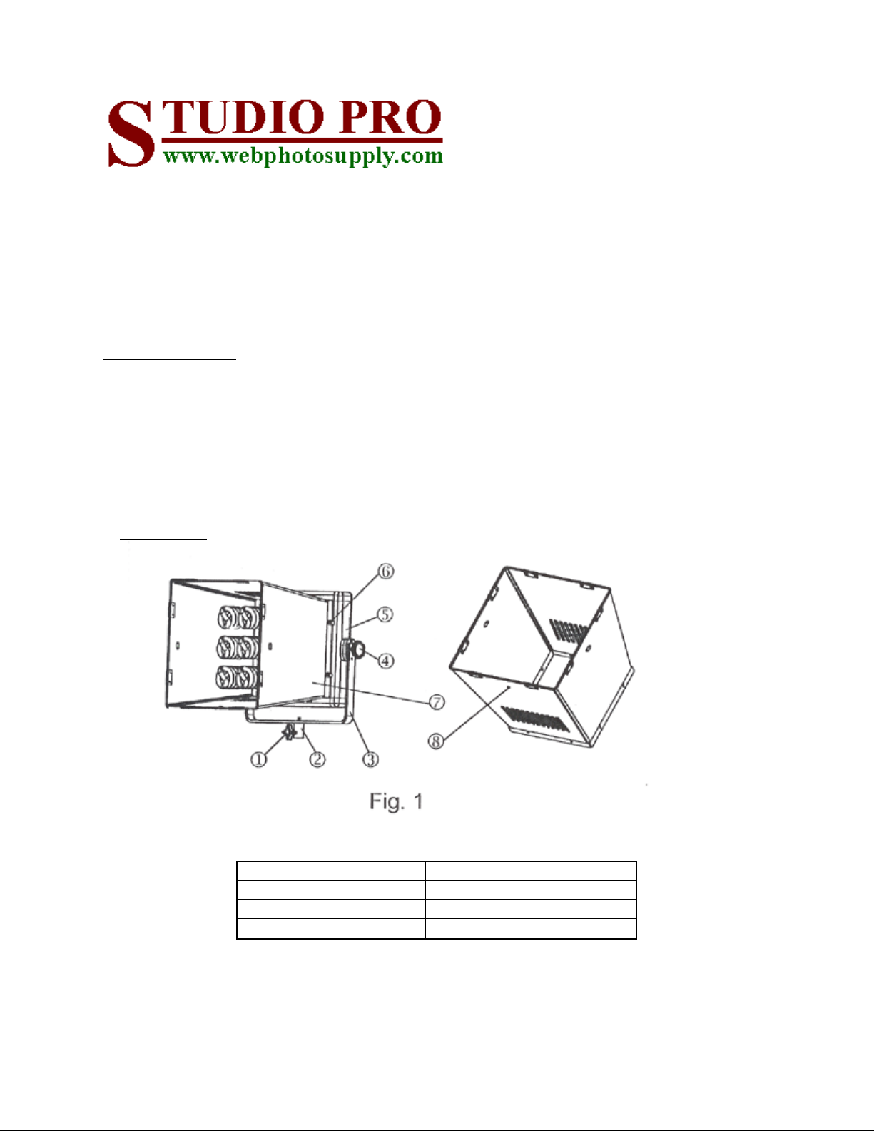
1. Main Parts
1 Sleeve Locking Knob 5 Body
2 Mounting Sleeve 6 Setting Screw Knob
3 Mounting Frame 7 Reflector
4 Frame Locking Knob 8 Hole for Supporting Rod

2. INSTALLATION
a) Installing the Light:
Generally the Light is to be installed on a light stand. A light stand with sufficient
sturdiness and an appropriate leg-spread diameter which matches the size and weight of
the particular light model must be used.
Loosen the Sleeve Locking Knob to clear the passage inside the Mounting Sleeve. Insert
the head of the light stand into the Mounting Sleeve. Then, tighten the Sleeve Locking
Knob (see Fig. 1).
b) Putting on the Reflector:
Mount the Reflector on the Body and lock it in place with the Setting Screw Knobs. The
wider side of the Reflector, where the flaps are linked together, is the front side. The
narrower side is to be mounted to the Body. Make sure the flap of the Reflector, which
has the Hole for the Supporting Rod, is the bottom side.
c) Installing the Supporting Rod (see Fig. 2)
i) The lower end of the Supporting Rod takes the form of a clamp. Mount this clamp to
the shaft of a light stand (more or less immediately above the top of the tripod
section) and tighten the Supporting Rod Clamping Screw to lock it in place.
ii) The upper end of the Supporting Rod takes the form of a threaded stud on top of a
plastic disc mounted to a ball joint. Remove the Butterfly Nut first. Then, insert the
stud into the Hole for the Supporting Rod on the bottom flap of the Reflector. Rotate
the shaft of the last section of the rod, if necessary, to adjust the orientation of the
plastic disc such that the disc surface can come into contact squarely with the bottom
flap of the Reflector (if this is not done, the bottom flap of the Reflector can be
deformed when the Butterfly Nut is put back). Finally, put back the Butterfly Nut to
lock everything in place.

d) Installing Spiral Fluorescent Lamps
Make sure the lamps are for the local voltage. Screw them into the sockets on the front of
the Body.
e) Installing the Diffuser Panel
The Diffuser Panel has 2 rectangular “Wings”, one bigger than the other (Fig. 3), sticking
out from 2 of its edges. There is a gap around the front edges of the Reflector. Insert the
bigger “Wing” of the Diffuser Panel into the gap on the top side and the smaller “Wing”
into that on the bottom side.
f) Setting the Tilt Angle
Loosen the extension points of the Supporting Rod first so that the movement of the light
during adjustment will not be obstructed. Loosen the Frame Locking Knobs on both sides
of the Mounting Frame slightly. Tilt the light to the desired angle and locking it in
position by tightening the Frame Locking Knobs. Tighten the extension joints on the
Supporting Rod to complete it.
3. OPERATION
a) Make sure the light is for the local voltage.
b) Set the ON/OFF Power Switch to the “OFF” position before plugging it in.
c) Turn on the unit. Light will come on and gradually intensify. Normal operating
intensity will be reached in just a few moments.
4. LIGHT INTENSITY ADJUSTMENT
Light intensity adjustments can be achieved through one or more of the following ways:
a) Power Level Adjustment (Model SFL925 and SFL1625 only)
Different power levels can be obtained by setting Switches 1 and 2 on the back of the unit
(Fig. 4) according to the following table:
SFL 925 SFL 1625
Switch 1 ON OFF ON ON OFF ON
Switch 2 OFF ON ON OFF ON ON
Power Level 1/3 2/3 FULL 3/8 5/8 FULL

b) Addition of Intensifier (Optional)
i) Function
The Intensifier is something similar to a snoot in terms of its function and is for
concentrating the light beams into a smaller area, thus enhancing the brightness for that
area.
ii) Installation
There are 2 Mounting Plates on 2 opposite sides of the frame of the Intensifier (Fig. 5).
Each of the Mounting Plates has a hole and there are matching holes on the left and right
side of the Reflector. Install the Intensifier onto the Reflector with these holes lining up.
The 2 Mounting Plates of the Intensifier should be on the outside. Screw the provided
Setting Screw Knobs into the matched holes to firmly attach the Intensifier to the Reflector.
c) Beam Angle Adjustment
If an Intensifier is being used, opening or closing the angles of the 4 flaps of the Intensifier
can decrease or increase the intensity respectively.
5. INSTALLATION OF SOFT BOX (Optional)
Soft boxes of different sizes are available as optional items. To install a soft box, the
Supporting Rod and Reflector must be removed first. Then, mount the soft box (Fig. 6) to
the Body and lock it in place by tightening the Setting Screw Knobs.

6. CAUTION
a) The light is designed solely for indoor usage.
b) Always turn off the light or unplug it when not in use.
c) The exterior of the unit can reach a temperature of as high as 55 degrees Celsius
during operation. All flammable materials must be kept at a minimum distance of 0.5
meter from any external surface of the unit. The spiral fluorescent lamps and the
interior of the unit will reach even higher temperatures during operation and should
never be touched with bare hands until they have been cooled down sufficiently.
d) To prevent electrical shock hazard, do not immerse the unit in any liquid, spill any
liquid over the unit or attempt to disassemble the unit.
e) A spiral fluorescent lamp must be replaced if it has become damaged or deformed.
unplug the unit and allow the lamps to cool down sufficiently before replacing lamps.
f) The spiral fluorescent lamps contain mercury inside. Consult local hazardous waste
disposal regulations and make sure they are complied with when disposing the lamps.
g) If the power cable of the unit is damaged, it must be replaced and replacement work
must be carried out only by the manufacturer, their service agent or any electrical
technician qualified to carry out electrical work under the local regulations in order
to avoid electrical hazard.
NOTE
“Most fluorescent bulbs contain mercury, a hazardous material with special rules for
disposal.
But the new sub-CFLs contain such a small amount of mercury that the EPA has stated it
is safe to dispose of them normally.”
Quote by the Clean Air – Cool Planet Environmental Group.
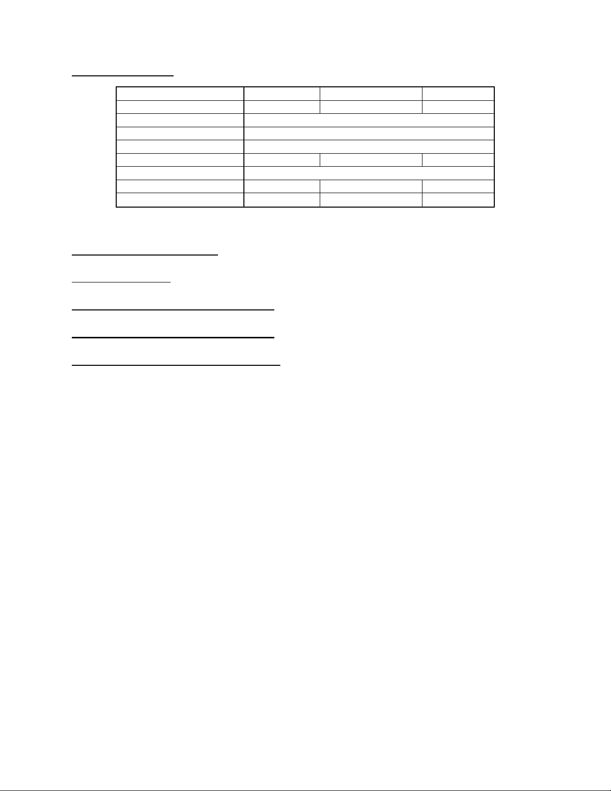
SPECIFICATIONS
Model No. SFL 425 SFL 925 SFL 1625
Rated Power 100 Watt 225 Watt 400 Watt
Operating Temperature 5-35 degree Celsius
Bulbs YPZ 120/25 SD, 110-120V, 25 Watt
Color Temperature 5200 Kelvin
Power Levels Full Full, 2/3, 1/3 Full, 5/8, 3/8
Power Source 110-120V, 60Hz
Dimensions (mm) 310x310x270 390x390x410 500x500x500
Weight (kg) 3 6 9
AVAILABLE SOFTBOXES
(Dimensions in mm)
SFL425: 600 x 600, 600 x 690, 900 x 900
SFL925: 600 x 600, 600 x 690, 900 x 900
SFL1625: 600 x 600, 600 x 690, 900 x 900
This manual suits for next models
2
Table of contents
Popular Lighting Equipment manuals by other brands

Paradise Datacom
Paradise Datacom GL23716 quick start guide

Commercial Electric
Commercial Electric HPLA11CWB user guide

Techno Signz
Techno Signz Digi Pilot Sign troubleshooting guide

WE-EF
WE-EF XRY300 LED Series Installation and maintenance instructions

Bresser
Bresser BR-SP60 instruction manual

Qazqa
Qazqa Cage Rack WL 2 Black 105135 instruction manual


