LG HBP10H User manual

16/04/2021
INSTALLATION MANUAL
Residential
Battery unit
Part 2
LG Electronics strongly advises users to exercise due care in following LGE’s
product installation manual. A warranty claims are invalid if damage is
caused by human error, inconsistent with the installation manual.
MODEL
LG HBP10H
(BLGRESU10HP)
Read in conjunction with Part 1.

19
4 Commissioning
4.1 LED Indicators
The LED indicators on the front of the battery pack show its operational state as follows:
LED 1
(Power) LED 2
(Charge) LED 3
(Discharge) LED 4
(Fault) Status
Power on (lnit)
- - - Ready
Normal
- - Charge
- - Discharge
- - Fault 1
- - Fault 2
(Every 10 s)
- - - Power-saving
----Power O
(Quickly)
- - - Updating
FW Update
-Update
Complete
-Update Failed
There are four LED indicators on the front of the battery packs to show its operating status.
1. Power On(Init) : Initialization for operating the battery
2. Ready : Battery is ready for operating normally.
3. Charge : Battery pack is charging.
4. Discharge :Battery pack is discharging.
5. Fault : Battery pack is warning state. Fault1 is blinking. Fault 2 is continuous. See
Section 5 Troubleshooting guide for detail condition.
6. Power saving : Battery stay in minimum self consumption power mode.
7. FW update : Battery is in update sequence. See the detail LED indication about
Updating, Update complete, Update failed.
4.2 Powering On the Battery Pack
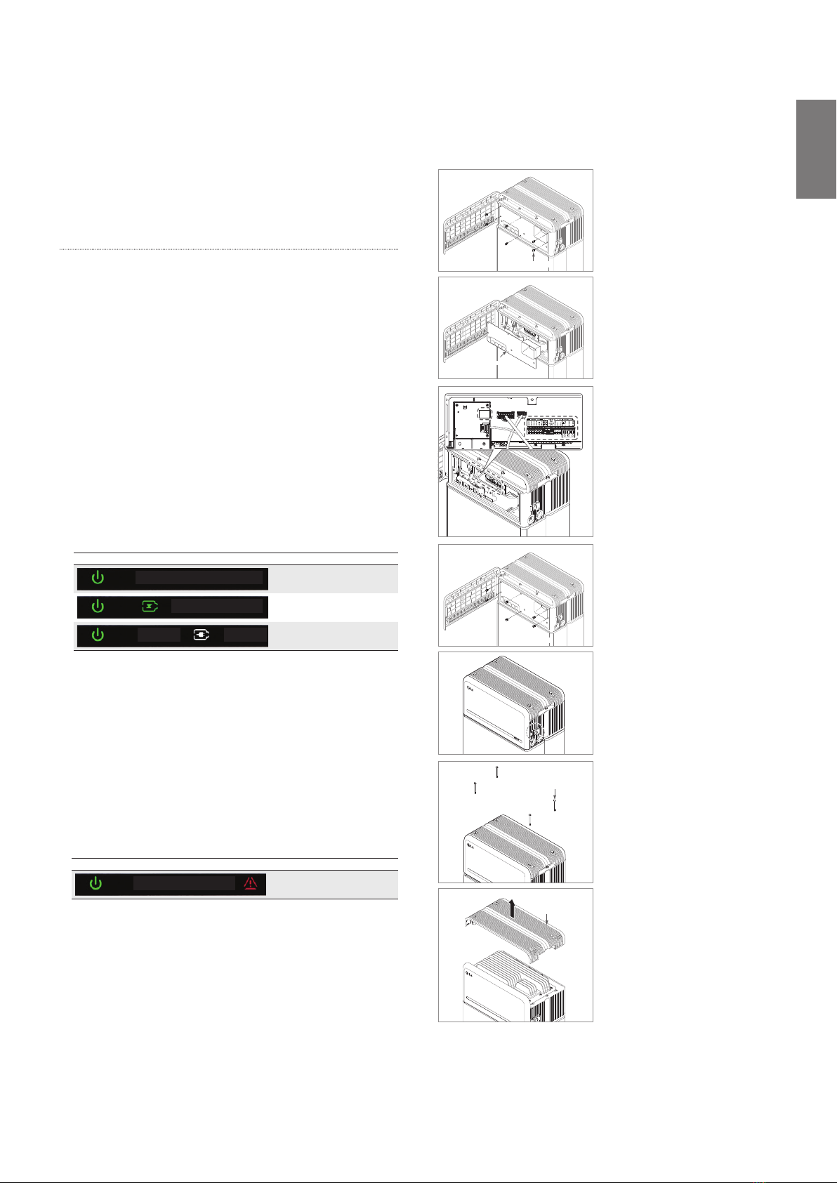
Power on the battery through the following steps:
1. Open the front cover.
2. Ensure the circuit breaker switch is in the OFF position.
3. Turn on the circuit breaker.
4. Seconds after the circuit breaker switch is ON, four (4) LED indicators will light
up.
5. Ensure the LED power indicator is ON to conrm that the battery pack has
successfully initialized. The LED power indicator on the front should be green.
6. Close the front cover.
7. Turn on the inverter.
CAUTION
If it stays o, indicates FAULT or fails to operate, do not use the battery pack and contact LG
Electronics or your distributor.
4.3 Shutting O the Battery Pack
Shut o the battery packthrough the following steps:
1. Turn o the inverter.
2. Open the front cover.
3. Turn o the battery pack by moving the circuit breaker switch to the OFF
position.
4. Make sure that every LED indicator on the battery pack is OFF. (After 10
seconds, the LED lights will turn o and the battery will shut down completely.)
5. Close the front cover.
5 Troubleshooting
5.1 Troubleshooting Overview
Check the LED indicators on the front to determine the state of the battery pack. A fault state
is triggered when certain conditions like voltage or temperature are beyond design limitations.
The battery pack’s BMS periodically reports its operating state to the inverter.
When the battery pack falls outside of prescribed limits, it enters a fault state. When a fault is
reported, the inverter immediately terminates operation.
Use the monitoring software on the inverter to identify what caused the fault state. The possible
warning messages are as follows:
•Battery Overvoltage
•Battery Undervoltage
•Battery Over Temperature
•Battery Under Temperature
•Battery Discharge Overcurrent
•Battery Charge Overcurrent
•Battery Overcharge Power Limit
•Battery Overdischarge Power Limit
•BMS Internal Error
•External Communication Error
•Internal Communication Error
•Battery Cell Deviation Voltage
•Battery Pack Undervoltage
•Battery Urgent Undervoltage
The fault state is cleared when the battery pack resumes normal operation. If battery pack is not
working correctly and the issue persists, contact a qualied sta, Installer or LG Electronics
regional contact service point.
NOTE
For serious warnings, if no proper corrective action is taken by the inverter, the battery
pack’s circuit breaker will automatically trip to protect itself.
CAUTION
If the battery pack or the inverter indicates FAULT or fails to operate, contact LG
Electronics regional contact point or your distributor immediately.
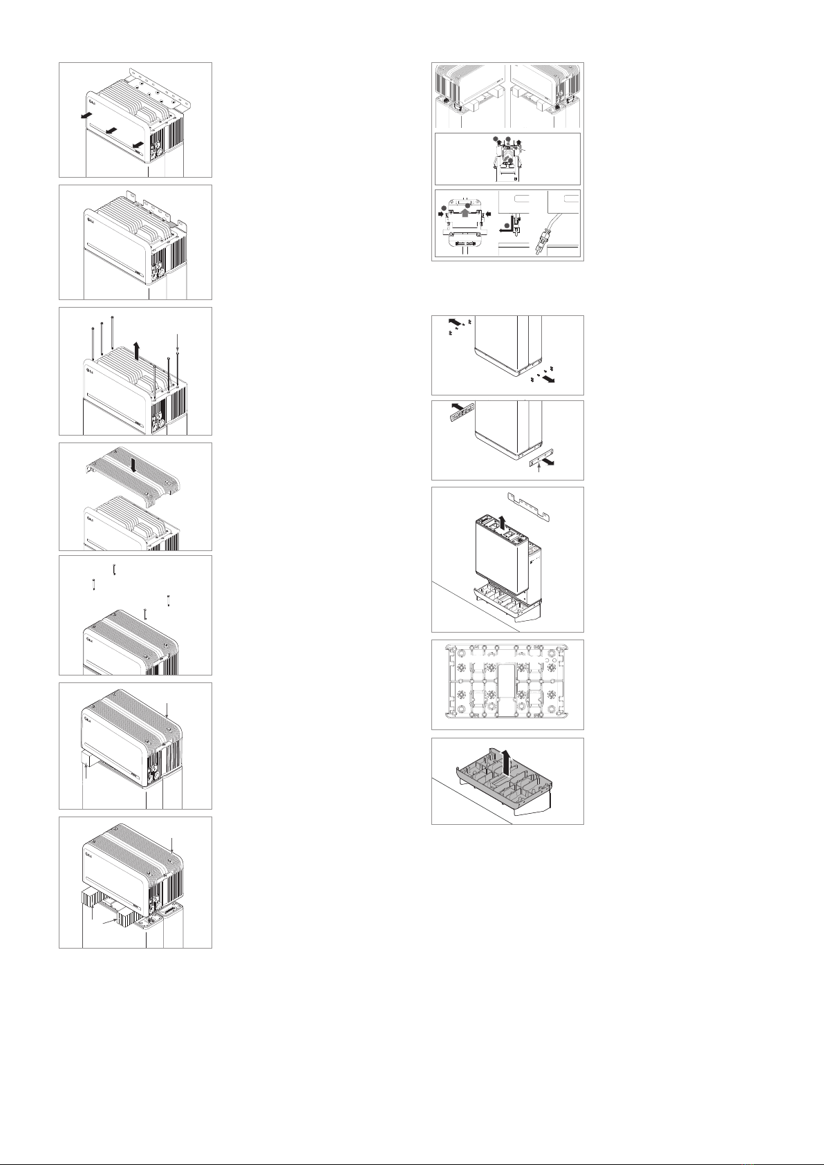
5.1.1 Post-Installation Checklist
Yes No
1. Visually check if the wiring matches the installation manual. (Section
3.3 Cable Connections.)
2. The circuit breaker is ON.
3. The battery LED power indicator is ON.
4. The inverter power is ON.
5. The inverter has the latest rmware installed. 1)
6. The inverter recognizes the battery. 2)
7. The battery is operational after installation.
7-1. TheAC grid is connected.
7-2. The meter is installed.
7-3. Government approval is complete.
8. IF ANY ITEM IN #7 IS CHECKED AS "NO" OR IF THE INVERTER
NEEDS TO BE TURNED OFF, TURN OFF THE CIRCUIT
BREAKER. 3)

ENGLISH
20
5.1.2 Troubleshooting Guidelines
If the battery LED power indicator is OFF
1. Turn o the circuit breaker.
2. Turn o the inverter. Verify there is no power at the battery connection.
3. Unplug all the wires and reconnect. Check that the wiring on the battery has been
done correctly. Refer to Section 3.3 Cable Connections.
4. Turn on the circuit breaker.
5. Turn on the inverter.
6. If the LED power indicator is still OFF, turn o the circuit breaker.
7. Disconnect the power cable connector.
8. Contact LG Electronics regional contact point.
1) Contact the inverter manufacturer.
2) Refer to the inverter installation manual or troubleshooting guidelines.
3) Refer to the Installation manual (3.3 Cable Connections) for the location of the battery. and
the Circuit Breaker.
If the LED power indicator is ON, but the battery is not charging or discharging
1. Update both the inverter and battery rmware versions. Refer to the inverter’s
troubleshooting guide for instructions.
2. Check the inverter’s battery settings. Refer to the inverter’s troubleshooting guide
for battery setup instructions.
3. If the battery is recognized, inverter setup has been completed successfully.
4. If the issue persists:
4-1. Turn o the circuit breaker.
4-2. Turn o the inverter. Verify there is no power at the battery connection.
4-3. Unplug all wires and reconnect. Check that the wiring on the battery has been done
correctly. Refer to Section 3.3 Cable Connections.
4-4. Turn on the circuit breaker.
5. If the battery setup is correct, but the battery is still non-operational, turn o the
circuit breaker
6. Contact LG Electronics regional service contact point.
LED Status Action
Power on
Charging
Discharging
If the LED fault indicator is ON
1. Check if the inverter recognizes the battery. Refer to the inverter’s troubleshooting
guide for battery setup instructions.
2. If the inverter is connected to the internet, collect the log les from the inverter
company.
2-1. Send the fault ID to LG Electronics regional contact point.
2-2. Turn o the circuit breaker.
2-3. Wait further instruction from LG Electronics.
3. If the inverter is not connected to the internet, check the inverter LCD to read the
battery’s fault ID. Refer to the inverter’s troubleshooting guide for instructions.
3-1. Send the fault ID to LG Electronics regional contact point.
3-2. Turn o the circuit breaker.
3-3. Wait further instruction from LG Electronics.
LED Status Action
Fault
6 Uninstallation & Return
6.1 Return/Replacement Instructions
6.1.1 Uninstallation
Uninstall the battery pack in the following order:
M5 PH Bolt 6ea
Front Protection Cover
1. Switch the inverter OFF before
beginning uninstallation of the battery
pack.
2. Switch circuit breaker OFF and make
sure it is in the OFF position.
3. Open the front cover, loosen 6 bolts
and remove the Front Protection
Cover.
4. Disconnect the cables.
Placethe spacer
Inthe line HERE
Placethe spacer
Inthe line HERE
P
P
la
c
c
c
ethe spa
c
er
I
nthe line HERE
nthe line HERE
nthe line HERE
nthe line HERE
nthe line HERE
nthe line HERE
nthe line HERE
nthe line HERE
nthe line HERE
nthe line HERE
nthe line HERE
5. Re-attach the Front Protection Cover
with M5 PH bolt 6ea.
Placethe spacer
Inthe line HERE
P
la
c
ethe spa
c
er
I
nthe line HERE
Placethe spacer
Inthe line HERE
P
la
c
ethe spa
c
er
I
nthe line HERE
Placethe spacer
Inthe line HERE
Placethe spacer
Inthe line HERE
Placethe spacer
Inthe line HERE Place the spacer
Inthe line HERE
Placethe spacer
Inthe line HERE
Placethe spacer
Inthe line HERE
M5xL65 Flange Bolt
Top Cover
6. Loosen 4 bolts and remove the Top
Cover.

21
Standing type:
7-a. Loosen six (6) M6 bolts and disassemble
Standing Bracket #2 ( at). Then move
the battery pack o the wall and remove
Standing Bracket #1 from the wall.
Wall Mounting type:
7-b. Loosen three (3) M6 bolts and
disassemble Wall Mounting Bracket Top
Support.
M5xL200 Flange
long Bolt
8. Loosen six (6) long bolts.
Placethe spacer
Inthe line HERE Placethe spacer
Inthe line HERE
Placethe spacer
Inthe line HERE
Placethe spacer
Inthe line HERE
Placethe spacer
Inthe line HERE
P
la
c
ethe spa
c
er
I
nthe line HERE
Placethe spacer
Inthe line HERE
P
la
c
ethe spa
c
er
I
nthe line HERE
Placethe spacer
Inthe line HERE
ethe spa
c
er
nthe line HERE
Placethe spacer
Inthe line HERE
9. Re-attach the top cover.
* Tighten the M5xL65 Flange Bolt
(4ea) with a torque of 5N·m.
Placethe spacer
Inthe line HERE
P
la
c
ethe spa
c
er
I
nthe line HERE
Placethe spacer
Inthe line HERE
P
la
c
ethe spa
c
er
I
nthe line HERE
Placethe spacer
Inthe line HERE
P
la
c
ethe spa
c
er
I
nthe line HERE
Battery Control Unit
Spacer
10.Place the rst spacer on top of the
Battery Modules.
* Be careful not to pull the cables
tight by lifting the Battery Control
Unit excessively. It may damage the
cables or disassembly of connector.
Placethe spacer
Inthe line HERE
P
la
c
ethe spa
c
er
I
nthe line HERE
Placethe spacer
Inthe line HERE
P
la
c
ethe spa
c
er
I
nthe line HERE
Placethe spacer
Inthe line HERE
P
la
c
ethe spa
c
er
I
nthe line HERE
Battery Control Unit
Spacer
11. After that, place the second spacer on
top of the Battery Modules.
Placethespacer
Intheline HERE
P
la
c
ethespa
c
er
I
ntheline HERE
Placethespacer
Intheline HERE
P
la
c
ethespa
c
er
I
ntheline HERE
Placethespacer
Intheline HERE
P
la
c
ethespa
c
er
I
ntheline HERE
Placethespacer
Intheline HERE
P
la
c
ethespa
c
er
I
ntheline HERE
1
2
3
12
3
Power connector
TPA
Sensing connector
Front
Front
12.Disconnect the power and sensor
connectors on the right and left sides
(2 each). This step should undergo
a deliberate visual inspection by the
installer before proceeding.
1) Power connector: APull the TPA
and Bpress the button at the
center of the connector. Then C
pull out the connector vertically.
2) Sensor connector: APush in the
sides of the connector and Bpull
out the connector vertically. Then
Cpull the connector out to the
side of the Battery Module.
* Be careful of damage to the sensor
connector’s guide pins during
disassembly.
* At this stage, DO NOT lift the
Battery Control Unit until all
connectors are disassembled.
Front
Front
Module Support BRKT
Front
Front
13.Disassemble Module Support BRKTs
with six (6) bolts each.
* Loosen the M6 Flange Bolts (x12)
14.Repack the Battery Modules.
Wall Mounting Base
Bottom View
Bottom View
Wall Mounting Bracket Bottom
15.(Wall Mounting Type only)
Loosen eight (8) M8 bolts and
remove the Module Connect Plate.
Then remove the Wall Mounting
Bracket Bottom.
16.Repack all remaining parts.

ENGLISH
22
6.1.2 Contact Information
Damaged batteries are dangerous and must be handled with extreme caution. They are not t
for use and may pose a danger to people or property. If the battery pack seems to be damaged,
contact LG Electronics regional contact point or your distributor. Use the contacts below
for technical assistance. These phone numbers are available only during business hours on
weekdays.
Service Contact
Europe Service Address LG Electronics ESS Solar Service
E-Service Supro GmbH Stolberger Str. 25
06493 Harzgerode
Telephone (Germany) 0049 (0)39484 / 976 380
(Austria) 0043 (0)720 / 11 66 01
(Switzerland) 0041 (0)44 / 505 11 42
(Benelux) 0031 (0)20 / 225 1660
Email [email protected]
Germany
Corporation Address LG Electronics Deutschland GmbH
Alfred-Herrhausen-Allee 3-5 65760 Eschborn
Telephone 0049 (0)18 / 06 807 020
Email [email protected]
Benelux
Corporation Address LG Electronics Benelux B.V.
Krijgsman 1, 1186 DM, Amstelveen, The
Netherlands
Telephone 0031 (0)20 456 3100
Australia Technical
Support &
Customer
Service
LG Electronics Australia Pty Ltd
Telephone 0061 1300 131 005
Email [email protected]
Australia
Corporation Address LG Electronics Australia Pty Ltd
2 Wonderland Drive, Eastern Creek, NSW 2766,
Australia
Telephone 0061 1300 152 179

23
7. Appendix
7.1 Connection in BLG RESU10HP parallel battery system
CAUTION
Parallel battery system can only be applied between products of the same energy.
7.1.1 Setting for communication termination resistor (About Section
B)
Section A Section B Section D Section E
Section C
When you install the pack as primary, Turn ON the DIP switch for communication termination
resistor.
When you install the pack as secondary, Turn OFF the DIP switch for communication
termination resistor.
Primary
Pack
Inverter
Terminating
resister ON
(already have)
(already have)
Inverter
Primary
Pack
Terminating
resister ON
1. Case 1 : When installing one battery
pack, Turn ON the DIP switch for
communication termination resistor.
(It is ON when switches are lowered.)
7.2 RMD Applications
7.2.1 BatteryStatuscheckviaRMD
How to check the battery status is as follows.
1) RMDWi-Fidirectconnection
First, proceed with RMD Wi-Fi direct connection as shown below.
Search and access the SSID of the RMD AP from a device (hereinafter referred to as a device)
supporting WLAN Station functions such as a smartphone.
RMD SSID has a structure of “RESU_ (or RMD) + RMD WLAN STM MACADDRESS”.
For the devices below, the SSID of the RMD SoftAP is “RESU_44CBXXXC14F (or
RMD44CBXXXC14F)”. The password is 12345678(changeable)
2) RMD Web page access
1. Start a web browser on the device and enter 192.168.4.1 in the address bar. If the
following screen is displayed after input, you have successfully connected to the
RMD web server.
2. Enter the password and click ‘Register’ to go to the home screen.
3. The default password is set to 123456 and can be changed in the Web UI.
3) Battery Status Check
Go to ‘Monitoring’ – ‘BMS’ tab of RMD Web page and check the value in the red box. If the
value is not ‘0x0000(or 0x00)’, refer to the Trouble shooting table below and take action.

ENGLISH
24
Fault Name error code Support action required
Over Voltage Fault2 DiagResultFault2 0x0001 Return the battery to LG
Electronics.
Under Voltage Fault2 DiagResultFault2 0x0002 Battery pack On and check
additional errors. In case of
normal operation, Charge the
Battery pack to over SoC 5%
with inverter.
Retrieve pack if issue occurs
repeatedly.
Over Temperature Fault2 DiagResultFault2 0x0400
1. If there is a heat source
nearby or the wind of the
air conditioner is directly
hitting it, remove the heat
source.
2. Lower the temperature
down to room temperature.
Rest until Battery
temperature matches room
temperature, then turn on
the CB. Retrieve pack if
issue occurs repeatedly.
Under Temperature Fault2 DiagResultFault2 0x0800
1. If ice built up on the
battery surface. Remove
ice.
2. Increase the temperature
up to room temperature.
Rest until Battery
temperature matches
ambient temperature, then
turn on the CB. Retrieve
pack if issue occurs
repeatedly.
Over Charge Current Fault2 DiagResultFault2 0x0020 Check if the setup/wiring is
connect properly and inverter
con gurations are valid, then
turn on the CB.
Retrieve pack if issue occurs
repeatedly.
Over Discharge Current
Fault2 DiagResultFault2 0x0040
Over Charge Power Limit
Fault2 DiagResultFault2 0x0080
Over Discharge Power Limit
Fault2 DiagResultFault2 0x0100
External Communication
Failed (BMS-DC/DC LOC) DiagResultFault2 0x4000
Check the communication
line.
If there is no abnormality
in the communication line,
battery pack on and check
additional errors.
Retrieve pack if issue occurs
repeatedly.
Internal Communication
Failed (MCU-BMIC Comm.
In BMS) DiagResultFault2 0x2000
Reconnect the cable between
Top cover assy and BMA.
Retrieve pack if issue occurs
repeatedly.
BMS Internal Fault2
DiagResultHwFault2 0x0004
Try restarting the battery.
Retrieve pack if issue occurs
repeatedly.
DiagResultHwFault2 0x1000
DiagResultFault2 0x10000
DiagResultHwFault2 0x0001
DiagResultHwFault2 0x0008
DiagResultHwFault2 0x0200
DiagResultHwFault2 0x0100
DiagResultHwFault2 0x0040
DiagResultHwFault2 0x0002
DiagResultHwFault2 0x2000
Pack Under Voltage Fault2 DiagResultFault2 0x0008
Battery pack On and check
additional errors.
In case of normal operation,
Charge the Battery pack to
over SoC 5% with inverter.
Retrieve pack if issue occurs
repeatedly.
Urgent Under Voltage Fault2 DiagResultFault2 0x0004 Return the battery to LG
Electronics.
Sudden Voltage Drop Fault2 DiagResultFault2 0x80000 Return the battery to LG
Electronics.
Cell Deviation Voltage Fault2 DiagResultFault2 0x4000000 Return the battery to LG
Electronics.
7.2.2 BMS,DC/DCandRMDUpdateviaRMD
Have to download the rmware before starting the update, visit the LG ESS Battery Website
and check the ‘Home Battery Partner’ > ‘Technical Support’ menu.
1) RMDWi-Fidirectconnection
First, proceed with RMD Wi-Fi direct connection as shown below.
Search and access the SSID of the RMD AP from a device (hereinafter referred to as a device)
supporting WLAN Station functions such as a smartphone.
RMD SSID has a structure of “RESU_(or RMD) + RMD WLAN STM MACADDRESS”.
For the devices below, the SSID of the RMD SoftAP is “RESU_44CBXXXC14F(or
RMD44CBXXXC14F)”. The password is 12345678(changeable).
2) RMD Web page access
1. Start a web browser on the device and enter 192.168.4.1 in the address bar. If the
following screen is displayed after input, you have successfully connected to the
RMD web server.
2. Enter the password and click ‘Register’ to go to the home screen.
3. The default password is set to 123456 and can be changed in the Web UI.

25
3) BMS, DC/DC and RMD Update
Can upgrade F/W. Upgrade is performed on the following three targets.
- RMD
- BMS
- DC/DC
1. Click the ‘Con g’ button
2. Click the ‘Update’ button
3. According to the target you want to
update, click the 'Choose File' button.
4. Select a update le
5. After checking if the le is selected
correctly, click the 'Send' button.
6. If you check the success message in
the upper right corner, the update was
successful.
7.2.3 InstallationviaRMDforwebuser
7.2.3.1 UserAgreement
Visit https://resumonitor.lgensol.com and Sign in.
A
B
CD
E
F
G
H
Click Installation → User Agreement and search the product which you will install.
Select your region (Non EU/EU).
Get the agreement of privacy policy for the customer. If the customer agrees the privacy policy,
have customer’s personal information.

ENGLISH
26
7.2.3.2 Battery Installation (RMD Setup)
A
B
D
C
Click Installation → Battery Installation and select the device the prepared device list.
Search and access the SSID of the RMD AP from a device (hereinafter referred to as a device)
supporting WLAN Station functions such as a smartphone.
RMD SSID has a structure of “RESU_(or RMD) + RMD WLAN STM MACADDRESS”.
For the devices below, the SSID of the RMD SoftAP is “RESU_44CBXXXC14F(or
RMD44CBXXXC14F)”. The password is 12345678(changeable).
Click “Con g” button for RMD setting on the RMD web. (The web browser will be re-directed
to RMD web address 192.168.4.1)
7.2.3.3 RMDWebLog-in
Enter the password and click ‘Register’ to go to the home screen. The default password is set to
123456 and can be changed in the Web UI.
7.2.3.4 Congsetting
1. Server Use: Decide whether to use (connect) to the cloud server.
2. Inverter Type: N/A
3. BMA Number : Select number of Modules: Select 2
4. Communication Type: N/A
5. Country: Select country.
6. Time Zone: Hour: Option to display ±1hour in UTC.
7. Time Zone: Minute: Option to display 15-minute unit.
8. Power Save Timer: N/A
9. Operating Mode: Must select ‘With BMS’
10.IotHub Connection String: Enter a unique String used to access theAzure
IoTHub(Cloud Server). String format is as follows:
HostName=emashub.azure-devices.net;DeviceId=
XXXX;SharedAccessKey=OOOO=
* For more information on how to obtain strings, refer to Section 3.2.1.2
Obtaining IoT Hub String
11. After completing all settings, click the Save button.

27
7.2.3.5 ServerConnection(Wi-Fisetting)
(If you have an Ethernet connection and don’t want to use Wi , skip this part)
Enter the Network → Wi-Fi tab.
1. Click the Scan AP button on the top right
of the Web UI.
2. The number of APs available is displayed
in a pop-up window.
3. Select the AP to access from the SSID
combo box, enter the password and click
the Connect button(Manual input is
possible).
4. If the connection to the AP is successful,
a pop-up window informs whether the
connection was successful as follows:
7.2.3.6 Check the Installation Status
Enter the Monitoring → Server Tab. Check the Status values are ‘OK’. Whether the Ethernet
connection or Wi-Fi connection ‘OK’ depends on the server connection method. An example is
the case of Wi-Fi connection.)

Other manuals for HBP10H
1
This manual suits for next models
1
Table of contents
Other LG Camera Accessories manuals

LG
LG Energy Solution RESU10H Prime User manual

LG
LG CAM Plus User manual

LG
LG RESU16H Prime User manual

LG
LG CHEM RESU10H User manual

LG
LG HBP10H User manual

LG
LG ICR18650B3 Owner's manual

LG
LG RESU 10H User manual

LG
LG ESS HB 10.0 User manual

LG
LG AJ-LAH2 User manual

LG
LG RESU FLEX Operating and maintenance instructions