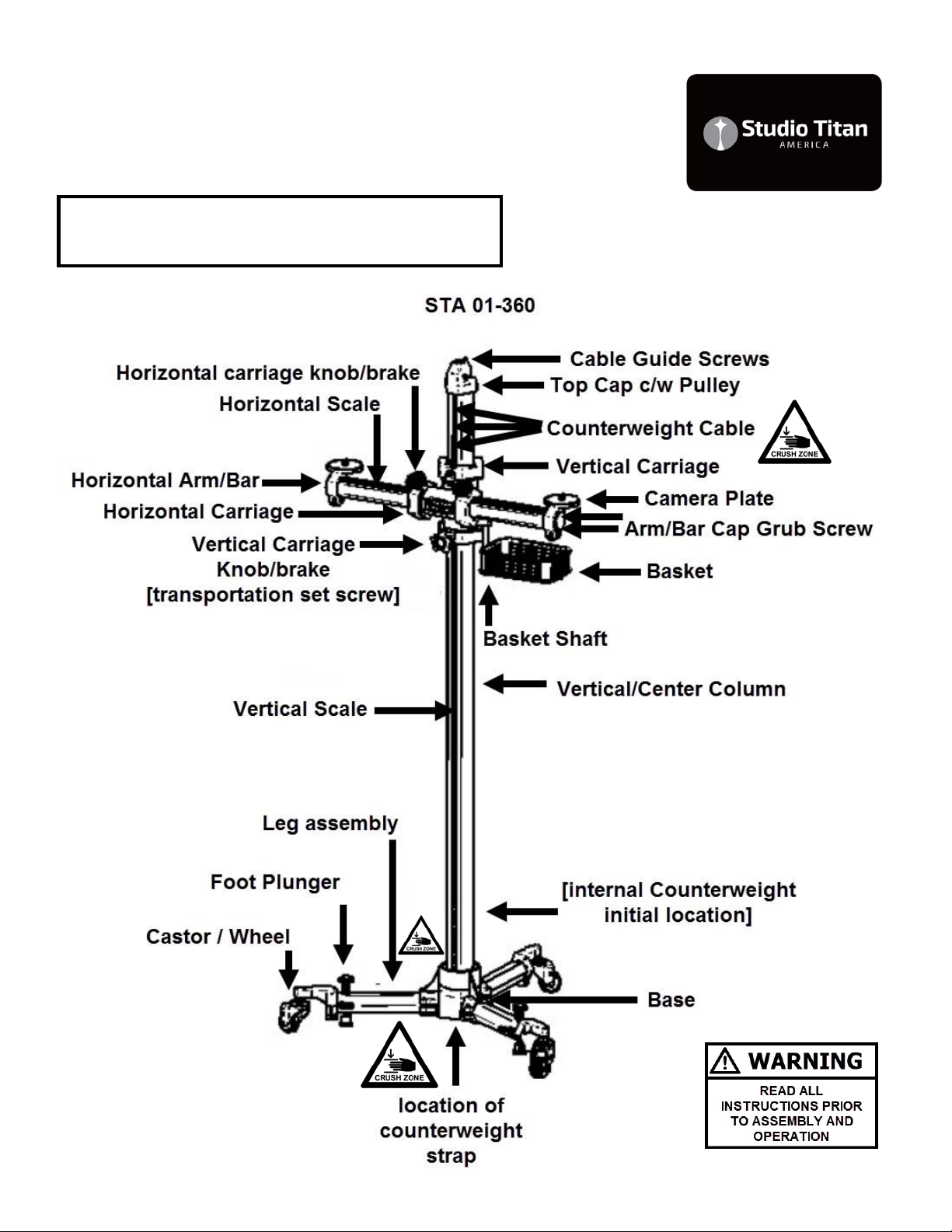
Studio Titan STA 01-360 User manual

STA 01‐360 series 1
CAUTION: Use leather work gloves and safety glasses when handling the box, when
opening the box and when assembling the product.
HAZARD: Strapping is under tension and can jump when cut. Strapping and Buckles,
Protective Edging, Plastic Walls, Plastic Caps and Product Components and parts should be
handled with care. Work slowly, use extra caution to avoid any sharp edges.
Additional Tools may be Required: The essential tools are included. The following tools
are recommended to be on site: Box Cutter, Scissors, Screw Driver, Plyers or Adjustable
wrench, Metric Hex / Allen Key set

STA 01‐360 series 2
Transit Damage:
Each package is inspected prior to being shipped
from the warehouse to insure that is in perfect condi-
tion. The column shipping boxes are constructed us-
ing extra thick cardboard. Some packaging includes
engineered plastic walls, end caps and banding. The
columns are packed using engineered plastic walls
and in dense foam to protect and absorb energy
from reasonable drops and impacts. The column
packaging is designed and drop tested from approxi-
mately 5 feet [1.5 Meters] without sustaining any in-
ternal damage. The packaging is crush tested using
a 660lb [300kg] weight placed along the long side of
the box without sustaining any internal damage. If
handled without care the boxes will show signs of
transit damage. Wearing work Gloves, while follow-
ing the Assembly Steps, carefully inspect the con-
tents inside the boxes. Specifically the Vertical cen-
ter column top cap pulley should be securely fas-
tened to the top of the Vertical center column as
shown on the [component identification] page. In the
base, the transportation counterweight securing
strap should be secured to the counterweight. [See
Diagram: E] If anything seems unusual, !!!STOP!!!
Send images to: info@studiotitanamerica.com for a
second opinion. If there are damaged OR Loose
parts, do not assemble the stand, you may injure
yourself. If the damage is noticeable such as cracks
or loose or broken parts contact your dealer for ex-
change. If the damage is minor or cosmetic and
does not compromise the safe assembly or opera-
tion of the stand send images of the parts that are
affected to: [email protected]. We will
make arrangements to provide you with replacement
parts to restore the stand to new condition.

STA 01‐360 series 3
Intended use:
This product is intended for use by professional
and commercial photographers in a studio envi-
ronment with a high ceiling. The wheels are de-
signed to be used indoors on a floor that is
smooth, hard, flat and unobstructed. The Studio
Stands with internal counterweight are designed
to be used at all times with a load (Camera or
laptop shelf or both). CAUTION: This product is
not recommended for use by hobbyists or in a
household environment with a low ceiling or car-
peted floors. Carpeting or pitted surfaces are
not recommended because of the increased
rolling resistance which can cause the stand to
tip over. If the surface is not ideal, the stand
must be moved with CAUTION, very slowly, us-
ing both hands one at the top and the other at
the bottom to steady the stand in order to pre-
vent the stand from tipping over. If the surface is
not ideal, lower the load to waist level before
moving the stand. We also recommend the use
of a sandbag or weight attached at the base
when conditions are not ideal to prevent tipping
over. Ultimately it’s the users responsibility to
understand how the stand operates and to use
the stand within its specification limits, as in-
tended to insure their own safety and the safety
of their equipment. It is also recommended to
use a short tether cable to secure the camera to
the stand in the event that the head, head plate,
attachment stud or camera adapter plate comes
loose or fails. Some assembly is required, we
recommend using an assistant during the initial
product assembly. Please read all documenta-
tion prior to assembly.

STA 01‐360 series 4
Component Identification: STA 01-360

STA 01‐360 series 5
Component Identification: STA 01-360

STA 01‐360 series 6
Assembly Steps:
1 Wearing Gloves and together with your Assis-
tant…Wearing Gloves …..Place the Column Box
[long rectangular box] flat on floor. Place some
packing materials on th floor. Do not remove and
stand the Vertical/Center Column vertically. Re-
move the Vertical/Center Column and Lay the
Vertical/Center Column flat on the floor. Under the
Base, Visually inspect and Confirm that the Coun-
terweight strap is present securing the counter-
weight to the counterweight stop pin. [See Dia-
gram: D] Do NOT remove the Counterweight
strap until advised later. If the strap is present
proceed to step 2 with assembly. If NOT, then fol-
low instructions below:
If Counterweight strap is NOT present: the coun-
ter weight is loose and can move inside the col-
umn. Do not stand the column vertically. Stop the
SET-UP and Contact us through the Studio Titan
America website for further instructions. Please
email: info@studiotitanamerica.com with the best
phone number to reach you. We normally re-
spond within 24hrs, during weekdays.

STA 01‐360 series 7
Assembly Steps:
2 Attach the three Leg Assemblies to the base.
[See Diagram: A] The Hex Key tool is supplied
and fasteners are supplied attached to the Base.
Use the supplied Hex Key Loosen the fasteners,
insert the legs and then re-tighten by hand. Note:
two of the leg assemblies are supplied with foot
plungers. To have direct access to the foot plung-
ers you will want to install the foot plungers facing
the operator or on the same side of the stand that
the Horizontal and Vertical scales face. [If the
floor is polished or on an angle consider ordering
a third leg assembly with plunger. This is a special
order, please email [email protected]
for additional information].
3 Wearing Gloves, using a screw driver, remove
the counterweight transportation securing band.
[See Diagram: D] !!!CAUTION!!! DO NOT IN-
SERT OR PUT FINGERS INSIDE THE BOTTOM
OF THE VERTICAL COLUMN OR BEYOND THE
COUNTERWEIGHT PIN. THE COUNTER-
WEIGHT IS HEAVY AND CAN INJURE YOUR
FINGER. [See Diagram: E]
4 Locate and identify the counterweight cable
from the component identification page. !!!
CAUTION!!! AVOID CONTACT WITH THE
COUNTERWEIGHT CABLE AT ALL TIMES.
CAUTION MUST USED TO AVOID FINGER OR
HAND INJURY DURING SET-UP AND NORMAL
OPERATION. The counterweight cable may be-
come frayed during transportation or normal use.
When frayed, stop using the stand and immedi-
ately replace the cable. Cable strands that sepa-
rate may become sharp.

STA 01‐360 series 8
Assembly Steps:
5 Together with your Assistant…Wearing Gloves
…..Carefully, Slowly raise and lift until the Vertical/
Center Column until it is standing freely on its
wheels.
6 Locate the M8 Hex Wrench. Remove the two
M8 x 20 bolts from the Vertical carriages. [See DI-
AGRAM: B] Locate the Horizontal Arm/Bar Car-
riage Assembly See [component identification]
page. Together with your assistant. Have your
assistant hold the Horizontal Arm/Bar Carriage
Assembly in place while you fasten it with the two
M8 x 20 bolts. Note the order [See DIAGRAM: B]
[Bolt, Spring washer and then Flat washer]. Hand
tightening with the Hex Wrench is recommended.
If you have a torque wrench tighten the M8 bolts
to 45Nm or 33 lb/ft not more.
7 Locate the M6 Hex Wrench. Locate the loose
Vertical / Brake Knob. Locate the location of Verti-
cal Carriage / Brake Knob See [Transportation
Set Screw] [See DIAGRAM: D & B]. With the M6
Hex Wrench Remove the transportation set screw
and replace with Vertical Carriage / Brake Knob.
Turn the Vertical Carriage /Brake Knob fully Clock
Wise to secure the vertical carriage in the upper
most or “parking position” [See DIAGRAM: D & B]

STA 01‐360 series 9
Assembly Steps:
8 Locate two M8 Hex wrenches. Locate the Bas-
ket. Locate the Basket Shaft, See [component
identification] page. With the first M8 hex key
hold the M8 bolt at the top of the Basket shaft.
With the second M8 hex key loosen the M8 bolt at
the bottom of the Basket shaft. Attach the Basket
to the Basket Shaft. Note the order of fastener
connection: [Bolt, Flat washer, Basket Plate, Flat
Washer]. [See: Component Identification page
and DIAGRAM: C]
9. CAUTION: [Only with the Horizontal Arm/Bar in
the upper most positon “parking position”.] Slowly
release the Vertical Carriage Knob/brake by turn-
ing it Counter Clock Wise. This will release the
vertical carriage allowing it to travel freely up and
down the Vertical Center / Colum. Confirm that
the Vertical Carriage is free to move in both direc-
tions while using both hands to hold the Horizon-
tal Arm/Bar. Turn the Vertical Carriage Knob/
brake fully Clock Wise to secure the vertical car-
riage.
10. Locate the Two Horizontal Carriage Knob/
Brakes, See [component identification] page.
Turn the Horizontal Carriage Knob/Brake Counter
Clockwise to release and confirm that the Hori-
zontal Arm / Bar is free to move left and right.
STOP SET-UP— Read below— GO TO STEP 11
If anything seems unusual or if the vertical car-
riage is not moving freely up or down. Stop Set-
up and send a few images of the stand to:
[email protected] for assistance.

STA 01‐360 series 10
Use & Maintenance Steps:
11 HAZARD: Stop and take a moment to under-
stand the effect of the counterweight. HAZARD:
The counterweight forces the vertical column to
travel towards the top of the Studio Stand. With-
out a load [Camera, laptop, etc] on the horizontal
Arm/Bar it can travel quickly towards the top of
the stand. HAZARD: Never use the stand without
a load [Camera, laptop, etc]. Always securely
“Park” the Vertical Carriage by Turning the Verti-
cal Carriage Knob/brake fully Clock Wise before
and after re-positioning or before the stand is un-
loaded [removing Camera, laptop, etc].
12 HAZARD: Work in such a way so your always
standing behind or in front of the stand so that
you always stand clear of the Horizontal Arm/Bar
and accessories. Take extra notice of your body
position when you are releasing the Vertical Car-
riage knob. With your free hand apply a down-
ward force to the Horizontal Arm/Bar Simultane-
ously as you release the Vertical Carriage knob.
13 Storage: Store with Vertical Carriage either in
the upper most “Parking Position” with the load
removed or store the Studio Stand with a weight
or sandbag on the Horizontal Arm/Bar to counter-
act the effect of the counterweight, in the event
that non-trained personal attempt to use the Stu-
dio Stand. Train all Studio personal prior to oper-
ating the Studio Stand.
14 Re-tighten all fasteners AGAIN. Re-tighten
fasteners after the first shoot. Tighten yearly.

STA 01‐360 series 11
Theory of Operation:
A studio stand is used by professional and com-
mercial photographers to capture images accu-
rately with repeatability. It provides a rigid and
stable platform essential for High Resolution Sen-
sors used in DSLR, Medium Format and Large
Format cameras and imaging systems. A studio
stand reduces vibrations that are present when
shooting hand held. Reduced vibration increases
image sharpness. It enables the photographer to
focus on subject matter and image composition
instead of hand holding the camera. It provides
creative shooting options using heights and an-
gles that are unachievable when hand holding a
camera. It provides the foundation stone that en-
ables the photographer to develop their own tech-
nical workflow. As the workflow evolves to in-
clude advanced imaging practices, the results can
be seen as sharper images.
With an adjustable camera head the user can ac-
curately set up the camera to maintain camera to
subject flatness of field in both the vertical and
horizontal planes of travel. The flatness of field is
maintained as the user moves the stand both ver-
tically and horizontally eliminating perspective dis-
tortion.
Shooting tethered with the optional laptop shelf,
reduces floor cabling and allows the photographer
to immediately confirm both focus and lighting.
A Studio Stand reduces user fatigue. The internal
counter balance offsets the weight of the camera
and computer. Allowing the user to easily move
the camera and computer up and down and left
and right using only one hand. This promotes
good body ergonomics which can prevent tennis
elbow.

STA 01‐360 series 12
Tip Over Hazard:
Caution must be used when moving the stand to
prevent tip over. Move the stand slowly and avoid
uneven surfaces as well as low and high level ob-
jects. Additional caution must be used when the Hor-
izontal arm with load (Camera or Laptop Shelf) is
used in the upper area above the midpoint of the
stand.
Counterweight Hazard:
The Horizontal Arm/Bar is connected to a counter-
weight located inside the Vertical Center/
Column. Caution must be used at all times when us-
ing the Horizontal Arm/Bar. The Vertical Carriage
Knob/Brake must always be tightened to lock the
Horizontal Arm/Bar in place. Without a load on the
Horizontal Arm/Bar it can accelerate upwards quick-
ly. When releasing the Vertical Carriage Knob/Brake
stand clear of the arms path of movement, firmly
hold the Horizontal Arm/Bar applying pressure down-
wards. Stand back to avoid contact with the Horizon-
tal Arm/Bar when unloaded. Do not remove the load
when the Vertical Carriage Knob/Brake knob is re-
leased or turned CCW. Unless repositioning the Ver-
tical Center/Column intentionally the Vertical Car-
riage Knob/Brake must be fully engaged (turned fully
clockwise). Store with Vertical Carriage either in the
upper most “Parking Position” with the load removed
or store the Studio Stand with a weight or sandbag
on the Horizontal Arm/Bar.

STA 01‐360 series 13
Assembly Diagrams:

STA 01‐360 series 14
Assembly Diagrams:

STA 01‐360 series 15
Assembly Diagrams:

STA 01‐360 series 16
STA 01-360 Specification
• Total Height : 192cm / 75.59 in
• Working Height Maximum : 180cm / 70.86 in
(measured from Camera Plate to floor)
• Working Height Minimum : 50cm / 19.7 in
(measured from Camera Plate to floor)
• Working Width Horizontal : 55cm / 21.6 in
(center of Column to center of Camera plate)
• Horizontal Arm/Bar total length: 700mm
Useful travel on 01-360 from center of Vertical
Center/Column to center of Camera plate:
Full Extension: 550mm as measured on one
side. Minimum Retraction: 140mm
• Width : 85cm / 33.46 in
• Weight : 30kg / 66lbs
• Suggested Wheels : 01-360-20-024 [contact
STA for identification prior to replacement. Updat-
ed Casters were introduced mid 2019 and are
NOT interchangeable due to the thread size. A
modification component is available to update
stands with the previous generation Casters.]
• Base Diameter : 90cm / 35.4 in
• Recommended General load capacity : 7kg
(15.4lbs)
• Camera Plate Hardware: 3/8th inch - 16
thread
• Includes two Camera Plates and Basket as
shown
WE RESERVE THE RIGHT TO MAKE PROD-
UCT CHANGES AND PRODUCT ENHANCE-
MENTS. PRODUCTS SUPPLIED MAY NOT BE
DELIVERED EXACTLY AS ADVERTISED OR
SHOWN ON THE WEBSITE OR IN THE MANU-
AL.
Other Studio Titan Camera Accessories manuals

Studio Titan
Studio Titan STA 01-350MK2 User manual

Studio Titan
Studio Titan STA 06-105 User manual

Studio Titan
Studio Titan STA-01-398 User manual

Studio Titan
Studio Titan STA 01-380 Series User manual

Studio Titan
Studio Titan STA-C01-360 User manual

Studio Titan
Studio Titan STA 01-360MK2 Series User manual

Studio Titan
Studio Titan STA 01-350R-MK2 User manual

Studio Titan
Studio Titan STA 01-397 U User manual