Stulz Tecnivel FAT User manual

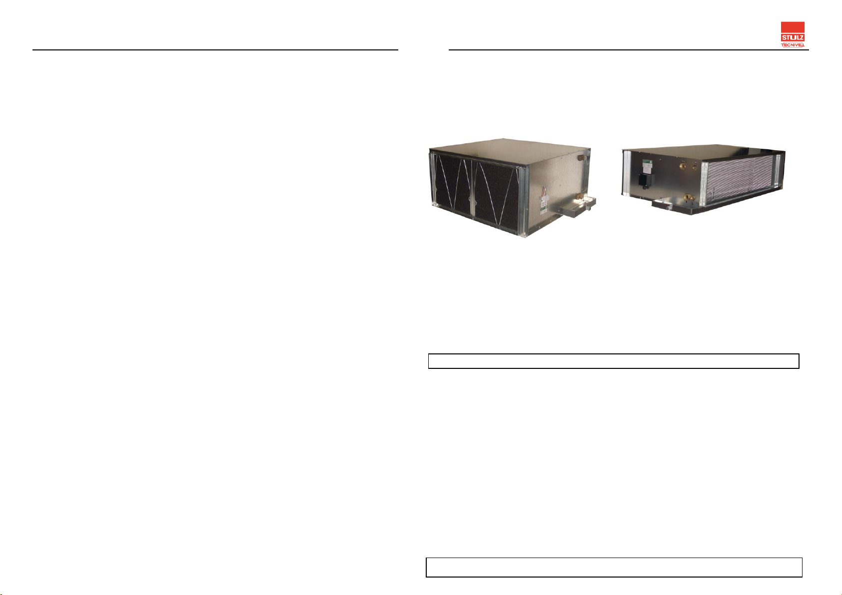
APARTMENT TYPE FANCOIL SERIES FAT/FAR
1. MANUFACTURER'S DATA
Corporate Name
Adress
St. Carabaña 25C - 28295 - Alcorcón
Madrid - Spain
Telephone +34 91 517 83 20
E-mail
info@stulztecnivel.com
STULZ TECNIVEL, S.L. C/ Navarra, parc 5
Pol. Ind. La Cardena, 45221 - Esquivias – Toledo
Contact information
2. INTRODUCTION
By means of this document, is intended to synthesize all the necessary information to install, use
and maintain in perfect conditions the Fan-coils of the FCH and V series, manufactured by STULZ
TECNIVEL, S.L.
The fancoils are equipment that are part of an installation and is forbidden the commissioning of the
unit until the whole installation fulfills with all applicable regulations and directives.
3. INSTALLATION AND ASSEMBLY INSTRUCTIONS
3.1 ANCHORAGE
There are four anchoring holes on the ceiling of the fan-coil, which are designed to allow the device
to hang from the ceiling. In order to level the device for proper operation, use threaded rod M-8.
It should be noted that it is
advisable to foresee a slight
drop towards the side of the
condensate drain that
facilitates its exit, avoiding
possible overflows of the
condensate collection tray.
(See Fig. 1)
In order to avoid vibrations transmission is
necessary that the anchorage points will be
isolated as indicated in Fig 2.
3.2 CONNECTION TO THE HIDRAULIC SUPPLY
Connect the unit to the cold and / or hot water supply keeping the diameter of the connections.
Support the connection fitting with a key to avoid deforming the collector. Avoid installing
reductions, this practice would cause an excessive pressure drop in the water, which would
negatively influence the performance of the device.
The entry of the water (cold or hot) will always be made by the lowest manifold. Failure to follow this
practice implies a defective operation of the unit, and hinders the purging of the installation.
3.3 CONNECTION TO THE ELECTRIC SUPPLY
It is necessary to connect the terminal strip, located on one side of the fan-coil, with the voltage
indicated on the rating plate plus grounding wire.
Remove the cover from the terminal block (pressure attached) and connect to its corresponding
terminals.
As indicated in the connection label that is located close to the unit electrical connections.
Tighten the screws of the terminals, pull lightly the cables that have been connected, to ensure that
they are firmly fastened and replace the cover of the power strip.
4. INSTRUCTIONS FOR THE COMMISSIONING
Put pressure on the fan-coil and make sure there are no leaks in any of the hydraulic connections.
Purge the battery using the bleeder installed for this purpose in the water outlet manifold (highest
connection).
Make sure that the voltage on the electrical supply matches that indicated on the rating plate.
Check that the filters are correctly positioned and that the mesh part face is oriented inside the fan-
coil.
It is possible that in the installation there are air pockets that will accumulate in the water outlet
manifold, preventing proper operation of the unit. It is recommended to repeat the purge operation
after ½ to 1 h of fan-coil operation.
5. MAINTENANCE INSTRUCTIONS
Every three months the filter / s that incorporate the fan-coils will be cleaned, and every three years1
it will be replaced by a new one.
The cleaning will be done by immersing the filter in soapy water, keeping it there for at least two
hours; rinse and let drain and aerate until drops of water are released
6. STANDARD OPERATING CONDITIONS
Operating situations in which neither temperature nor humidity are extreme are considered normal,
as well as environments free of agents that attack materials, such as in saline, excessively dusty
environments, etc.
The water entering the coil will be at a temperature between 4 and 90 ° C and it is understood that
the coil is designed for the circulation of water inside, so no other liquid should be used without prior
authorization from the manufacturer.
Working pressures will be less than 8 Kg/cm2.
_________________
1The data appearing in this Instruction Manual is considering a normal system of use of the device.
Fig. 1
Fig. 2
DRAIN
TRAY
APARTMENT TYPE FANCOIL SERIES FAT/FAR
7. OPERATING LIMIT CONDITIONS
In installations where it is foreseen that at some point the water may be close to 0 ° C, it is
recommended to add glycol antifreeze fluid to avoid damage of the exchanger by freezing.
In installations where the voltage differs from the rated voltage for which the unit is designed, it is
not guaranteed that the engine will maintain the conditions for which it was selected, and it is
understood that there is a danger of burning it.
8. RISK SITUATIONS
During the handling for the installation, there is a risk of cutting with the edges of the sheet forming
the housing of the unit.
The fan-coils incorporate fans with impellers, which in operation constitutes a risk, since they rotate
at high speeds, therefore, the manipulation of the unit with the fan in operation is forbidden, since
there are no devices that prevent access to the fan impeller.
9. ELIMINATION OR REDUCTION OF RISK
The power supply will be cut off before carrying out any intervention on the unit.
In order to avoid that the impeller of the fan constitutes a danger, a reasonable time will be waited
for the impeller to stop before manipulating the unit.
In any case, the intervention of a professional will be required to avoid unnecessary risks.
The staff that comes into contact with the unit will be provided with gloves as a means of protection
against possible cuts that may occur.
10. RESIDUAL RISKS.
Even if the fan-coil is completely stopped, during the heating season, it is necessary to be careful
when handling next to the water connections, since there is a risk of burns if the hot water inlet pipe
is touched.
The condenser that incorporates the motor remains charged, so incorrect handling could cause
damage.
Never operate the unit without it previous disconnection from all sources of energy.
MANUAL
APARTMENT TYPE FANCOIL FAT and FAR
INDEX
1. MANUFACTURER`S DATA.
2. INTRODUCTION.
3. INSTALLATION AND ASSEMBLY INSTRUCTIONS.
3.1. ANCHORAGE
3.2. CONNECTION TO THE HIDRAULIC SUPPLY
3.3. CONNECTION TO THE ELECTRIC SUPPLY
4. INSTRUCTIONS FOR THE START UP.
5. MAINTENANCE INSTRUCTIONS.
6. NORMAL CONDITIONS OF USE.
7. CONDITIONS OF LIMITATION.
8. RISK SITUATIONS.
9. ELIMINATION OR REDUCTION OF RISK.
10. RESIDUAL RISKS
This document is property of STULZ TECNIVEL, S.L., not being allowed its total or partial
reproduction without a prior express consent.
Rev 00.0
26/04/2018
This manual suits for next models
1
Other Stulz Tecnivel Accessories manuals

Popular Accessories manuals by other brands


PCB Piezotronics
PCB Piezotronics 117B237 Installation and operating manual

Vega
Vega VEGAFLEX 81 operating instructions

Ipuro
Ipuro AIR SONIC operating manual

netvox
netvox Contact Sensor Series user manual

PCB Piezotronics
PCB Piezotronics IMI SENSORS HT640B71 Installation and operating manual

KMC Controls
KMC Controls STE-6010 Application guide