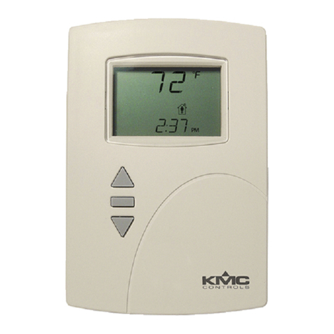
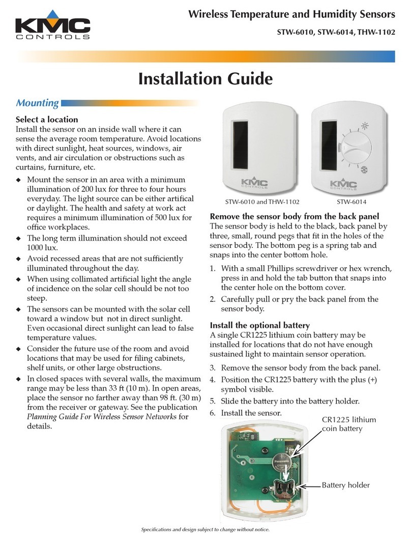
KMC Controls STE-6010 User guide

STE-6010/6011/6013/6015 Room Temperature Sensors 1 Application Guide, AN0412A
Application Guide
Room Temperature Sensors
STE-6010/6011/6013/6015
Models
Model
Number
Interface
Features
Cable
Connections
Override
Button
LED
Status
Indicator
Screw
Clamp
Terminals
RJ-45
Connector
EIA-485
Data
Port
STE-6010-10 X X
STE-6011-10 X
STE-6013-10 X X X
STE-6015-10 X X X X
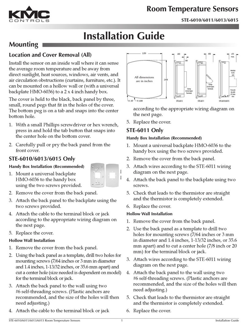
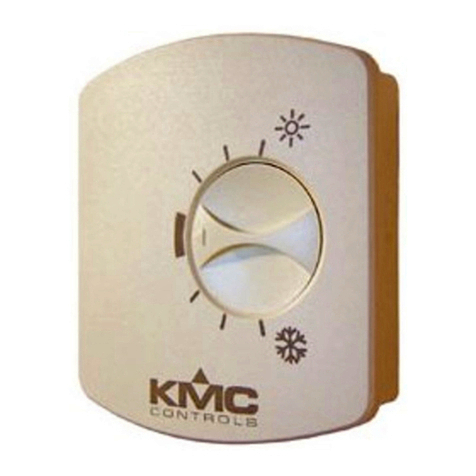
STE-6010/6011 STE-6013/6015
NOTE: Formoreproductinformation,seetheSTE-
6000 Series Room Temperature Sensors/
Transmiers Data SheetontheKMC
Controlswebsite.
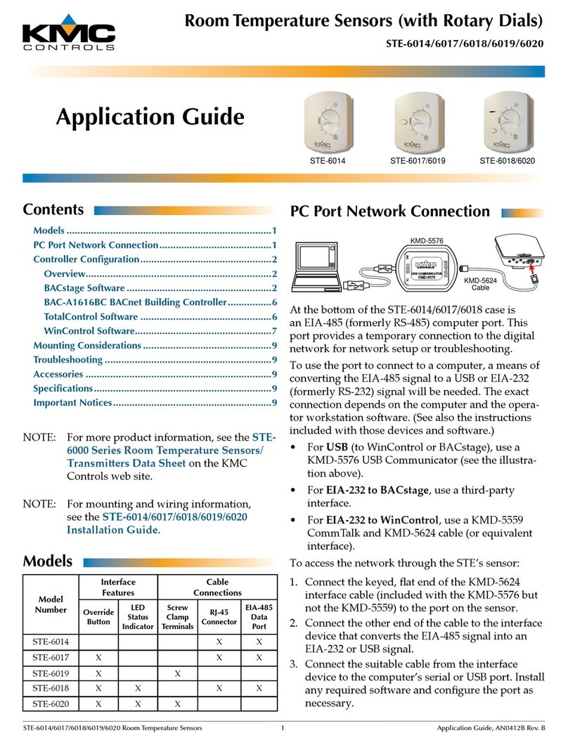
AttheboomoftheSTE-6010/6015caseisanEIA-
485(formerlyRS-485)computerport.Thisport
providesatemporaryconnectiontothedigital
networkfornetworksetuportroubleshooting.
Tousetheporttoconnecttoacomputer,ameansof
convertingtheEIA-485signaltoaUSBorEIA-232
(formerlyRS-232)signalwillbeneeded.Theexact
connectiondependsonthecomputerandtheopera-
torworkstationsoware.(Seealsotheinstructions
includedwiththosedevicesandsoware.)
• ForUSB(toWinControlorBACstage),usea
KMD-5576USBCommunicator(seetheillustra-
tionabove).
• ForEIA-232 to BACstage,useathird-party
interface.
• ForEIA-232 to WinControl,useaKMD-5559
CommTalkandKMD-5624cable(orequivalent
interface).
Toaccessthenetworkthroughthesensor’sport:
1. Connectthekeyed,atendoftheKMD-5624
interfacecable(includedwiththeKMD-5576but
nottheKMD-5559)totheportonthesensor.
2. Connecttheotherendofthecabletotheinterface
devicethatconvertstheEIA-485signalintoan
EIA-232orUSBsignal.
3. Connectthesuitablecablefromtheinterface
devicetothecomputer’sserialorUSBport.Install
anyrequiredsowareandconguretheportas
necessary.
KMD-5624
Cable
KMD-5576
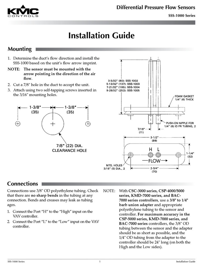
PC Port Network Connection
NOTE: Formountingandwiringinformation,see
theSTE-6010/6011/6013/6015 Installation
Guide.
Contents
Models ...........................................................................1
PC Port Network Connection .........................................1
Controller Configuration ................................................2
Overview ....................................................................2
BACstage Software .....................................................2
BAC-A1616BC BACnet Building Controller ................3
TotalControl Software ................................................3
WinControl Software..................................................3
Mounting Considerations ...............................................4
Troubleshooting .............................................................4
Specifications .................................................................5
Accessories ....................................................................5
Important Notices ..........................................................5

STE-6010/6011/6013/6015 Room Temperature Sensors 2 Application Guide, AN0412A
Controller Configuration
Overview
Ensure that the corresponding 10,000 ohm pull-up
resistors on the controller are selected (switched
On).Consultthecontroller’ssetupinstructionsfor
informationonswitchingonthepull-upresistors.
See the relevant soware section for controller
conguration instructions.
BACstage Software
Thermistor Input (All)
1. IntheBACstagesowaremainmenu,select
Objects>Inputs.
2. ClickEdit.
3. TypeinanameintheappropriateDescription
eld(upto32characters)and/orNameeld(up
to16characters).
NOTE: Notwolabelsordescriptionsinacontroller
canbeidentical.
4. SelectObject Type: Analogifitisnotthedefault.
5. SelectDevice Type: KMC10K Type II.
6. SelectUnits: °For°C.
7.Optionally,changetheFilter Weight(underMore)
tothedesirednumberofthermistorreadings
averagedbeforedisplayingtheresult.Ifthe
(STE-6013/6015)overrideisbeingused,Filter
Weight mayneedtobereduceddowntoward1
toensurereliablerecognitionofthebuonpress,
dependingonthecontroller.
NOTE: Thebuonneedstobepressedandheld
foratleastahalfasecondtobereliably
recognizedforoverridemode.
8. ClickEnd Edit.
9. ClickYesfor“SendUpdateNoticationNow?”
10.IntheBACstagesowaremainmenu,select
Device>Device Tables>KMC10K Type II Table.
11.ClickEdit.
12.ClickDefaults(valueswillllin).
13.ClickEnd Edit.
14.ClickYesfor“SendUpdateNoticationNow?”
15.ClickOK.
Override (STE-6013/6015 Only)
1.IntheBACstagesowaremainmenu,select
Objects>Binary Values.
2.ClickEdit.
3.TypeinanameintheappropriateDescription
eldand/orNameeld.
4. ClickintheUnitscolumnandselectO/On(or
No/Yes,Stop/Start,Disabled/Enabled,Inactive/Active
accordingtopreference).
5.ClickEnd Edit.
6.ClickYesfor“SendUpdateNoticationNow?”
7.ClickOK.
8.IntheBACstagesowaremainmenu,select
Objects>BASIC Programs.
9.ClickEdit.
10.TypeinanameintheappropriateDescription
eldand/orNameeld.
11.ClickAutorun.
12.ClickEnd Edit.
13.ClickYesfor“SendUpdateNoticationNow?”
14.Clickonceinthe #column.
15.Typeinprogramlines(seethefollowing
example).
NOTE: Thisisonlyanexample.Detailsneedtot
thecontrollerconguration.
10 REM ** AI3 IS STE-6013/6015
TEMPERATURE SENSOR INPUT **
20 REM ** BV3 IS OCCUPIED/UNOCCUPIED
(ON/OFF) MODE **
30 REM ** PUSH BUTTON ON SENSOR TO
START OVERRIDE MODE (BV2) **
40 IF+ SENSORON( AI3 ) AND NOT BV3 THEN
START BV2
50 REM ** CHANGE DEFAULT TIMEON TO
DESIRED AMOUNT OF OVERRIDE TIME **
60 IF TIMEON( BV2 ) > 02:00:00 THEN
STOP BV2
70 REM ** AO7 IS SUPPLY VOLTAGE FOR
STE-6013/6015 LED **
80 IF BV2 THEN AO7 = 10 ELSE AO7 = 0
90 END
16.ClickSend.
17.ClickOK.
18.ClickYesfor“ExecuteProgramNow?”
19.ClickClose.
20.ClickOK.

STE-6010/6011/6013/6015 Room Temperature Sensors 3 Application Guide, AN0412A
WinControl Software
Thermistor Input (All)
1.IntheWinControlsowaremainmenu,select
Control>Inputs.
2.ClickEdit.
3.TypeinanameintheappropriateDescription
eld(upto20characters)and/orLabeleld(upto
8characters).
NOTE: Notwolabelsordescriptionsinacontroller
canbeidentical.
4.ClickUnits(whichopenstheCongureInputs
screen).
5.SelectType: Analogifitisnotthedefault.
6.SelectDeg F(orC)KMC10K Type II.
7.Optionally,changeFormatfrom0tothedesired
numberoftemperaturedecimalplaces.
8.Optionally,changetheAveragetothedesired
numberofthermistorreadingsaveragedbefore
displayingtheresult.IftheSTE-6013/6015
overrideisbeingused,Average mayneedto
bereduceddowntoward1toensurereliable
recognitionofthebuonpress,dependingonthe
controller.
NOTE: Thebuonneedstobepressedandheld
foratleastahalfasecondtobereliably
recognizedforoverridemode.
9.ClickOK.
10.ClickEnd Edit.
11.ClickOK.
Override (STE-6013/6015 only)
1. IntheWinControlsowaremainmenu,select
Control>Setpoint/Variables.
2. ClickEdit.
3. TypeinanameintheappropriateDescription
eldand/orLabeleld.
4. ClickUnits(whichopenstheCongureVariables
screen).
5. SelectType: Digital.
6. SelectO/On(orNo/Yes,Stop/Start,Dis/Enabled
accordingtopreference).
7. ClickOK.
8. ClickEnd Edit.
9. ClickOK.
10.IntheWinControlsowaremainmenu,select
Control>Control Basic.
TotalControl Software
NOTE: Followtherelevanthardwareinstructions
intheBACstageSowaresectionor
KMDigitalSowaresection.Thensee
theTotalControlHelpinformationfor
theequivalentsowarecongurationin
TotalControl.
BAC-A1616BC BACnet Building Controller
Select the 10K ohm pull-up resistor jumper posi-
tion for the corresponding input.(SeetheInstalla-
tionsectionoftheBAC-A1616ABCBuildingControl-
lerInstallationandOperationGuideforthecorrect
jumperposition.)
BecausetheBuildingControllerhasa0–12VDC
totalinputrange,dierenttablesarerequiredthan
inother(0–5VDC)KMCcontrollers.Download the
sensor tables (CSV) le from the KMC Controls
Partners web site and import the needed tables
as described in the Tables section of the BAC-
A1616ABC Building Controller Installation and
Operation Guide. (You must log into the Partners
site to see the zipped tables le on the Building
Controller product page downloads.)
1.InthedesiredAnalogInputsetupscreenofthe
webpageinterface,selectKMCTypeIIDegree
FahrenheitorKMCTypeIIDegreeCelsius.
2.SelecttheLookupTablefortheTypeII
Thermistor.
3.FortheFahrenheitscale,themultiplieris1.8and
theosetis32.ForCelsius,themultiplieris1and
theosetis0.
4.ClickSave.
ForanexampleofOverridemodeControlBasic,see
theBACnetexampleinOverride (STE-6013/6015
Only) on page 2.
STE-6010/6011/6013/6015 Room Temperature Sensors 4 Application Guide, AN0412A
11.ClickEdit.
12.TypeinanameintheDescriptioneldand/or
Nameeld.
13.PlaceanxintheOncolumn.
14.Click End Edit.
15.Clickonceinthe#column.
16.Typeinprogramlines(seethefollowing
example).
NOTE: Thisisonlyanexample.Detailsneedtot
thecontrollerconguration.
10 REM ** STE-6013/6015 OVERRIDE **
20 REM ** VAR5 IS OCCUPIED/UNOCCUPIED
(ON/OFF) MODE **
30 IF NOT VAR5 THEN GOSUB 50
40 END
50 REM ** IN3 IS ROOM TEMP VOLTAGE FROM
SENSOR (FROM INPUT SCREEN) **
60 REM ** VAR4 IS OVERRIDE (FROM
SETPOINTS/VARIABLES SCREEN)**
70 REM ** USE BUTTON ON SENSOR TO START
OVERRIDE (VAR4) **
80 IF+ SENSOR-ON( IN3 ) THEN START VAR4
90 REM ** OUT7 IS SUPPLY VOLTAGE FOR
STE-6013/6015 LED **
100 IF VAR4 THEN OUT7 = 10 ELSE OUT7 =
0
110 REM ** CHANGE DEFAULT TIME-ON TO
DESIRED AMOUNT OF OVERRIDE TIME **
120 IF TIME-ON( VAR4 ) > 02:00:00 THEN
STOP VAR4
130 RETURN
NOTE: Foranadditionalsampleapplication
ofprogrammingoverridetimers,adapt
theinformationintheApplicationNote
AN0504FProgrammingOverrideTimers
sectionofthetheDigitalDesigner’sGuide
(SP-022).
Troubleshooting
• Besurethe10,000ohmpull-upresistorsonthe
controllerboardareturnedON.
• Checkwiring.Topreventexcessivevoltagedrop,
useaconductorsizethatisadequateforthe
wiringlength!
• Checksensorcongurationandtablesinthe
controller.
• Checkvoltagefromthecontroller.
• CheckthatthesensorisNOTmountedonan
exteriorwall,mountedonornearalargether-
malmass,blockedfromnormalaircirculation
byobstructions,exposedtoheatsourcesorto
sunlight,exposedtodrasfromwindowsorair
vents,orexposedtoairowthroughtheconduit
fromleaksinplenumducts.(SeetheMounting
Considerationssectionabove.)
Mounting Considerations
SensorsmustNOTbe:
• Mountedonanexteriorwall.
• Mountedonornearalargethermalmass(e.g.,
concreteblockwall).
• Blockedfromnormalaircirculationbyobstruc-
tions.
• Exposedtoheatsources(e.g.,lights,computers,
copiers,orcoeemakers)ortosunlight(atany
timeoftheday).
• Exposedtodrasfromwindows,diusers,or
returns.
• Exposedtoairowthroughtheconduit(from
leaksinplenumducts)—putplumber’spuyor
similarmaterialinsidetheconduittoblockair
ow.

STE-6010/6011/6013/6015 Room Temperature Sensors 5 Application Guide, AN0412A
KMC Controls, Inc.
19476IndustrialDrive
NewParis,IN46553
574.831.5250
www.kmccontrols.com
Accessories
HMO-6036 UniversalBackplate,Almond
HMO-6036W UniversalBackplate,White
KMD-569x STE-6010/6014/6015/6016/6017/
6018toControllerCablewithRJ-
45toRJ-11Connectors(-5693=25
.;-5694=50.;-5695=75.)
KMD-5624 PCDataPort(EIA-485)Cable
KMD-5576 EIA-485toUSBCommunicator
SP-001 FlatBladeandHexEndScrew-
driver
© 2012 KMC Controls, Inc. AN0412A
Specifications
Connections Clamp(screw-type)terminals
ormodularRJ-45jack(see
Models on page 1)
Material Flame-retardantplastic,light
almondorwhite
Weight Approx.1.25oz.(35grams)
Sensor
Type TypeIIthermistor
Accuracy ±0.36°F(±0.20°C)
Resistance 10,000ohms @77°F(25°C)
NTC 4.37%/°C@25°C
DissipationConstant2mW/°C
STE-6013/6015 (Only)
FrontBuon Onemomentarypushbuon,
shuntstemperaturesensorto
signaloverridecondition
LEDIndicator 10VDC(12VDCmax);5mA
max.currentdrawat12VDC
Approvals CEcompliant
Environmental Limits
Operating 34to125°F(1.1to51.6°C)
Shipping –40to140°F(–40to60°C)
Humidity 0to95%RHnon-condensing
Important Notices
Thematerialinthisdocumentisforinformation
purposesonly.The contents and the product it
describes are subject to change without notice.
KMCControls,Inc.makesnorepresentationsor
warrantieswithrespecttothisdocument.Innoevent
shallKMCControls,Inc.beliableforanydamages,
directorincidental,arisingoutoforrelatedtothe
useofthisdocument.
Other manuals for STE-6010
2
This manual suits for next models
3
Table of contents
Other KMC Controls Accessories manuals

KMC Controls
KMC Controls STE-6014-10 User manual

KMC Controls
KMC Controls STE-6014 User manual

KMC Controls
KMC Controls STE-1421 User manual

KMC Controls
KMC Controls STW-6010 User manual

KMC Controls
KMC Controls NetSensor KMD-1261 Operating instructions

KMC Controls
KMC Controls STE-6014 User guide

KMC Controls
KMC Controls SSS-1000 Series User manual

KMC Controls
KMC Controls KMD-1183 Operating instructions

KMC Controls
KMC Controls THE-1105 User manual

KMC Controls
KMC Controls STE-6010-10 User manual