netvox Contact Sensor Series User manual

User Manual
Wireless Window Door Sensor
And Wireless Glass Sensor
Model: Z311C
Contact Sensor Series
FW: V1.1
HW: V0.1~V1.0
20130604

Extended Magnet
Extended Contact
Internal Contact
Red/Green Indicator
Binding Key
Auxiliary Key
Glass-break sensor input
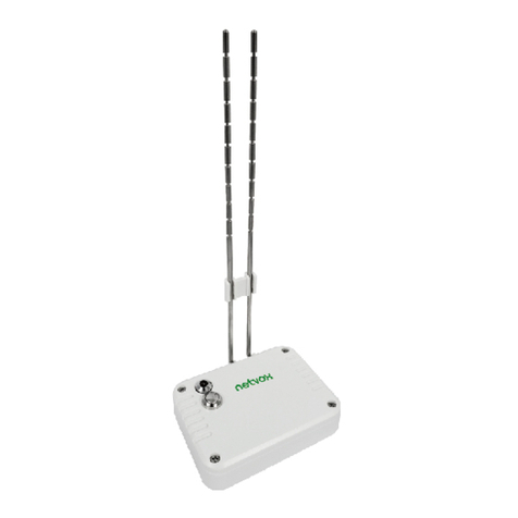
Figure 1: Z311C device
Extended Contact Input
Battery Cover
Glass-break sensor

Introduction
In an existing network, Z311C is an end device and does not permit join other devices like
router device does.
Z311C is an intrusion detect sensor for monitoring door/window and glass window in a
security system. The magnetic contacts are to be installed on between the gaps where the
door or window closes so that when the door opens the contacts moved away from each
other the device triggers the alarm system. With any vibration wave attempts to break the
window glass, the sensor triggers the alarm system in the device and notifies to its
corresponding enrolled CIE –Control and Indicating Equipment, security system in the
network. The CIE reads the information received, updates status changed and indicates
siren to sound. For the door/window application when the door is kept open, CIE would
receive door open notification and update the status until the door is closed and the CIE
will receive an update notification and replace the currently open-status with currently
close-status.
What is ZigBee?
ZigBee is a short range wireless transmission technology which defined for a minimum
complexity, low power consumption, low data rate, cost effective wireless solution. ZigBee
lies in between wireless markup technology and Bluetooth. ZigBee is based on
IEEE802.15.4 standard, the mutual co-ordination between thousands of sensors to
exchange data. Sensor to sensor or node-to-node communication is achieved through
relays of control data between devices with only a fraction of energy use which denoted
for highly transmission efficiency.
Note: Wireless communication, in some real use cases, can be limited by the signal
blockage. Please consult your service provider or place of purchase.
Product Specification
9Fully IEEE 802.15.4 compliant
9Utilizes 2.4GHz ISM band, up to 16 channels
9Up to 70 meters non-obstacle wireless distance
9Two CR2450 button batteries powered
9Simple operation and device configuration

Setting up the Z311C and network
When Z311C is powered up, it will search for an existing network and will ask to join the
network of the same channel automatically. If it is within a coordinator or other router
coverage area with permit-join feature is open, Z311C is permitted to join. Normally
there is 1 minute of permit-join period.
Network association operation:
Step 1: Make sure you have open up permit-join function (valid for 60 seconds) of a
coordinator or a router.
Step 2: Now turn on the Z311C device (refer to chapter Turn it on of this manual)
The device will start to search for the network within reach. If there is a network available
for join, the green indicator will flash once.
Step 3: The green indicator will flash 5 times upon join successful. Otherwise the
indicator will not flash. The device will enter to sleep mode after 15 seconds of attempt to
join. To wake up the device for another join attempt, please press any key.
Setting up Summary
(1) Device startup and network association
(2) Alarm system registration
(3) The device it is now ready to be used.
Step 1. Startup and NetworkAssociation
Notes:
a. By default the ZigBee network does not allow any devices to join, this is done this way
to prevent any potential unauthorized device join attempt. Make sure Z311C is within
the coverage area. You must first enable permit join feature on a router or a
coordinator already in the network so that the new device Z311C is permitted to join
when it searched the network channel.
b. On how to enable permit-join feature please refer to the coordinator or the router user
l

Notice: Before Z311C is powered on ready to join the network, make sure a coordinator or a router
that opens permit-join to allow Z311C to join is on. Make sure the device has successfully
joined to the network before going to the next step -Enrollment and CIE registering.
Most read Warning: Possible battery drainage
When the device was once joined to a network and by any
chance the network is no longer present or it is out of network - it
will wake up every 15 minutes to find the network it joined before.
It never goes to deep sleep but continues to find its network
every 15 minutes. This scenario can consume up to 50 times
power more than normal operation. To avoid this unwanted
power consumption, you need to manually switch off the sensors
when network is off

When the battery is loaded, Z311C enters power off mode. This ensures minimum power
losses. Any other button press or contacts will not activate power except binding key.
Turn it on
Please go to Step 2 now before you turn it ON.
To turn it on, short press binding key once and you will see the red indicator flashes
once. Now the power is on and the device is ready to search for any available network on
the air.
Turn it off
At any time when you want it to be off when it will not be used, you can simply short press
the binding key once the red indicator will flashes 10 times for 5 seconds. Before 5
seconds expires press the binding key again to turn it off. You will see the red light goes
off. If 5 seconds has expired and the key press is not applied within the period, Z311C will
return to power on condition.
* It is recommended to power off Z311C when not in use.
Z311C is a zone device in the security system. Soon after the network join, the next step is
to enroll itself into a CIE (Control and Indicating Equipment) security system device to
validate zone alarm feature. The registration will take place automatically soon after the
device joined to the network.
*notes: a CIE security system will normally embedded within a device (i.e. a Netvox
Z201B) or it could be a stand-alone CIE device.
Observing CIE registration:
To ensure enrollment is successful or not simply read the indicator light flashes:
(1) Right after the network join, see if red indicator light flashes twice indicating that there
is no CIE existed or no compatible CIE is on the network.
(2) If there is CIE and it has enrolled, Z311C will send an enrollment request to it. If
enrollment failed the red indicator flashes 4 times. Flash 6 times if successful.
(3) For any reason that Z311C has failed being registered, press the Auxiliary key at
anytime should initiates the registration process. The LED indicator will flash the same
as that described in (2).
Step 2. Automatic Zone Registration (enrollment)

How to use
After Z311C has registered to the security system it is on duty for intrusion monitoring. Any
changes in device status will be reported to the CIE security system. For installation
please read the Installation section.
Door/window application
When the internal magnetic contact piece is near or attached on the Z311C, the status is
normal (Figure A) and is reported to the CIE security system.
When the magnetic contact piece moved away from Z311C, the device changes its status
to alarm mode and a zone status change is reported to CIE system. Normally the siren or
a silent alarm device in the network will be triggered. In case that the device is not
registered to a CIE system, it will try to register first then sent out an alarm notification at
once.
Note:
1. CIE device must be always existed elsewhere in the network.
2. It is commended that only one status change within 2 seconds to avoid potential traffic
jam of communication.
Glass break detection application
The glass breaking vibration wave would cause the sensor attached on the glass to
vibrate which trigger the alarm status of Z311C; following this Z311C would read other two
door magnetic contacts conditions. If the door contacts are closed, the normal status is
restored and normal status is then reported. If the door contacts are open the alarm status
stays –alarm status and no status message is reported. In this case the alarm status is
uninterrupted which continues signaling to either siren devices or strobe lighting devices.
In case that somehow Z311C was not registered to the CIE security system, a door close
or open; or glass break detection would wakes up the device to initiate registration
process and sent status report to CIE device at once. This ensures the up time of the
monitoring device. Unregistered situation can be the absence of the CIE device in the
network either due to CIE device maintenance reason or a new CIE device introduced.

Assigning Z311C to a preferred CIE system
This feature is only available for user who has the relevant application software or
Netvox ZiG-BULTER to do this. Please go to ZiG-BUTLER section in this manual.
Z311C can be paired with a CIE system device (i.e. Z201B). When a change in security
status Z311C notifies bound CIE to trigger audible alarm or light strobe signal to notify the
user.
Observation:
(1) In the case that you are assigning Z311C to its already-registered CIE security
system, Z311C simply displays 6 red flashed on its LED indicator when reassignment
configuration is completed.
(2) In the case that you are assigning Z311C to a different CIE security system other
than the one registered, after new registration successfully took place Z311C sends
deregistering command to the already-registered CIE security system to remove its
Z311C’s information. The indicator shows 6 red flashes upon configuration completed.
For programmer and application developer only:
When doing so, changes of the CIE device IEEE address in the IAS_CIE_Address
attribute written in Z311C will take place. A new CIE IEEE address will be assigned to
and will be written on Z311C device. You will need software similar to ZiG-BUTLER to
perform this configuration.

Overcoming a sleeping device
The device is battery powered and is designed to enter sleep mode when not transmitting
to save battery power. Sometimes during system setup you would want to retrieve
information (i.e. IEEE address, short address) from the device. The device needs to enter
temporal wake mode to stay connected.
Operation:
1. Hold press on auxiliary key and binding key at the same time until you see the
indicator flash in red twice. Then release the keys.
2. Z311C broadcasts an announce packet with an IEEE address and a short address
information to the air. There is 2 minutes of active period to communicate itself with
other device on the network.
Periodical Heartbeat Notification
In a security system, it is important to know the condition of each zone device required by
most software or hardware monitoring system or end user. To meet this need, Netvox
engineer came up with a mechanism called the heartbeat of a device implemented within
the firmware of Z311C and other Netvox security zone devices.
When Z311C had just registered itself to the security CIE system, it sends the very first
heartbeat signal right after a successful registration. After that it initiates a periodic
heartbeat and send to the security CIE system in every one hour by factory default which
is configurable through software with heartbeat cluster implemented (for application
developer or Netvox ZiG-BUTLER user). The heartbeat contains heartbeat information,
low battery power notification and alarm status.
The configurable heartbeat period range is between 30 seconds to a maximum of 604800
seconds (7 days) anything bellow or above that range is invalid value. When configuring
the heartbeat period, anything above 10 minute will take the step of 10 minute increments.
That will be 20 min, 30 min, 40 min, etc. If you give any other number, the Z311C will take
the least value. (i.e. as you typed in 35min value, the Z311C will take 30 min value)
*Such heartbeat can be configured via ZiG-BUTLER please go to ZiG-BULTER section.

Restore to factory setting
Z311C is capable of data storage on power failure. If Z311C is unable to communicate
with its registered CIE device or if you wish to join it to a new network, a restore to factory
default is required
Operation:
Hold press auxiliary key and binding key together you should see 2 red flashes on the
indicator but do not release the keys yet at this time until you see another quick flashes
followed then release the keys. The device should restore to the factory setting and soon
enters power off mode automatically to save power.
Battery level reporting
Low power reporting
The working voltage for Z311C is between 2.1~3.6V DC. It performs the first battery level
check when the battery is loaded. The device performs battery level check in a period of
time. Anything bellow 2.1V, a battery-low report is sent to the network and its enrolled CIE.
Battery Level Notification
Z311C not only reports low power notification to notify the user but also sends battery
level in percentage value. This information is placed in Zone Status Change Notification
and is sent when the statues of Z311C changes.
Battery disposal
This device uses 2 CR2450 3volt button batteries. When the battery is bellow 2.1V DC,
the device will not work and the status indicator will steadily flashing to notify the user to
replace it.
Warning: Do not cast battery into the fire. The battery may be explosive and may cause
injuries.

The following Information is for the advance user or
developers only

Clusters of Home Automation for Z311C
Home Automation device feature is defined by the endpoint which contains functional
clusters. Table 1 lists clusters for the endpoint of Z311C. Zone Type attribute value is
0x0015 as Contact switch.
When the magnetic contact piece is moving away from the body of the device or a
detected glass-break, Z311C sends out Zone status attribute as Alarm1 having the
attribute value of 1 for alarmed.
When the magnetic contact piece is close or attached to it, Z311C sends out Zone status
attribute as Alarm1 having the attribute value of 0 for not alarmed.
Table 1: Clusters supported by the Z311C endpoint 0x01
Cluster ID for Z311C
Server side Client side
EP 0x01 (Device ID: IAS Zone(0x0402) )
Basic(0x0000) None
Power configuration(0x0001)
Identify(0x0003)
IAS zone ( 0x0500)

Identifier Name Type Range Access Default Mandatory
/ Optional
0x0000 ZCLVersion Unsigned
8-bit integer
0x00 –
0xff
Read only 0x03 M
0x0001 ApplicationVersion Unsigned
8-bit integer
0x00 –
0xff
Read only 0x15 O
0x0002 StackVersion Unsigned
8-bit integer
0x00 –
0xff
Read only 0x2A O
0x0003 HWVersion Unsigned
8-bit integer
0x00 –
0xff
Read only 0x0C O
0x0004 ManufacturerName Character
string
0 – 32
bytes
Read only netvox O
0x0005 ModelIdentifier Character
string
0 – 32
bytes
Read only Z311CE0ED O
0x0006 DateCode Character
string
0 – 16
bytes
Read only -- O
0x0007 PowerSource 8-bit
Enumeration
0x00 –
0xff
Read only 0x03 M
0x0010 LocationDescription Character
string
0 – 16
bytes
Read/write -- O
0x0012 DeviceEnabled Boolean 0x00 –
0x01
Read/write 0x01 M
Attributes of the Basic Cluster Information

Installation
The glass break detection is expandable for a large window or multiple windows by
connecting the sensors in series to Z311C, as illustrated in the figure bellow. Z311C uses
GS-380S glass beak sensor and can be connected in series up to a maximum of 10.
Note: If you do not wish to connect the extended magnetic contacts or/and the glass
sensor on the device, please keep the supplied jumper head attached on the pin
connection otherwise Z311C will not function properly.
9Make sure that the glass and magnetic contact sensor should not be swapped. The
correct connection configuration is shown in the figure bellow or in the first page.
9Do not connect glass sensor on the top in where extended magnetic contact should be.
9Make sure the jumper is connected if the extended magnetic contact cable is detached.
Glass break
Sensor 1
。。。。。。
Glass break
Sensor 2
Glass break
Sensor 3
Glass break
Sensor 4
Figure 3: Installation guide

Glass Break Sensor Specification
Model GS-380S from SENGATE
Power The sensor does not required external power connection other
than connection to Z311C
Noise proof GS-308 can effectively detect vibration generated from glass
breaking. It resists to any vibration from wind friction against the
glass, considered to produce false alarm giving Z311C a more
stable zone device.
Detection Range Radius of 180 cm
Detection Method Piezoelectric
Alarm Period 0.5sec.~6 sec
Alarm Output Semiconductor style switch, polarity, DC24V/40mA
Resistance at 13 ohm (max.) when normal.
Resistance at 10M ohm and more on alarm.
Operating
Temperature
-20oC to +55oC (-4oF to +131oF)
Mounting Position Indoor, surface of glass materials
Weight 26 g (0.92 oz)
Dimensions
(inches/mm)
36.5mm diameter x 11mm
Cable length Curling wire 120 cm (stripped bare wire)
Sensor extension 10 sensors maximum in series
Cable length in series: any

ZiG-BUTLER
*This section is for ZiG-BUTLER software user only
During device installation, you will go though permit join and device pairing. Most of
the time you need to physically access to a device that is out of your reach. It
becomes handy when you can program through a software on a PC wirelessly
things becomes much easier. Our ZiG-BUTLER allows you to do that. Of course,
any other 3rd party ZigBee enabled software is also applicable.
ZiG-BUTLER software is to be installed on a PC or a server. The system needs a
Z103 USB dongle or a ZigBee to PC hardware interface such as a Z202 gateway to
communicate with the ZigBee network.
Join Z311CA into the network
If your ZiG-BUTLER sees a coordinator or a router device, you should be able to
see the icon similar to the one bellow:

-point your mouse to either the coordinator or router device icon and right click.
From the menu select Set PermitJoin On.
When Z311C has successfully joined, you should see the Z311C device icon appeared in
ZiG-BUTLER.
View Zone Status
Move your mouse to the circle on top of Z311C icon (Figure B), then right click your mouse
should display menu and select Properties.
Figure A
Figure B
Z311C

A device information dialog screen appears, similar to the one bellow.
In the General tab, the red circle area is the information of status.Alarm1 shows “ON”
meaning door open is been detected. The door status is currently open.
.
Configuring Heartbeat of Z311C
Move your mouse to the featured icon of the Z311C device.
- Right click on the featured icon.
featured icon
Z311C
Figure C
Figure D

In the drop down menu, select Properties
A configuration box should appear similar to the one bellow.
-Click on Advance tab
Figure 4: Advance tab (IAS Zone)

Enter your desirable Heartbeat period in Hour, in Minute and in Second. Set anything
between 30 seconds to 168 hours
Then Click Set Heatbeat when done to sent this configuration to the remote Z311C.
Assigning Z311C to a preferred CIE system
Assigning the preferred CIE settings please follow the Configuring Heartbeat of Z311C in
the previous section. In Figure 4 if Z311C has registered in a CIE system, the CIE system
device IEEE address will be displayed otherwise it will be blank.
Click on the dropdown arrow next to the IAS CIE ADDRESS and select a preferred CIE
system device.
*Now make sure you have wake up Z311C device which normally go to sleep when idle.
On how to wake up Z311C please go to Overcoming a sleeping device section.
-Now click on the Set IAS_CIE_ADDRESS to send the setting to Z311C device.
*Notice: Z311C is an end device which runs on battery power. It is normally at sleep
mode when idle except at each heartbeat cycle. So before you click Set Heatbeat,
make sure you wake up the sleeping device so that it will be up and listening. On how
to wake up Z311C please go to Overcoming a sleeping device section.
This manual suits for next models
1
Table of contents
Other netvox Accessories manuals
netvox
netvox R718PA7 User manual
netvox
netvox RA0716 User manual

netvox
netvox R718UBB Series User manual

netvox
netvox R718J User manual
netvox
netvox Z307 User manual
netvox
netvox R718PE User manual

netvox
netvox R718PE User manual

netvox
netvox R311G User manual
netvox
netvox R313G User manual
netvox
netvox R718PQA User manual
netvox
netvox R313K User manual
netvox
netvox R311B User manual
netvox
netvox R711 User manual

netvox
netvox R718PB13 User manual
netvox
netvox R311CC User manual
netvox
netvox ZigBee Z801WLS User manual
netvox
netvox R313M User manual
netvox
netvox R718PA5 User manual

netvox
netvox RA0716 User manual
netvox
netvox R720F User manual

