TABLE OF CONTENTS
OVERVIEW....................................................................................................................................... 3
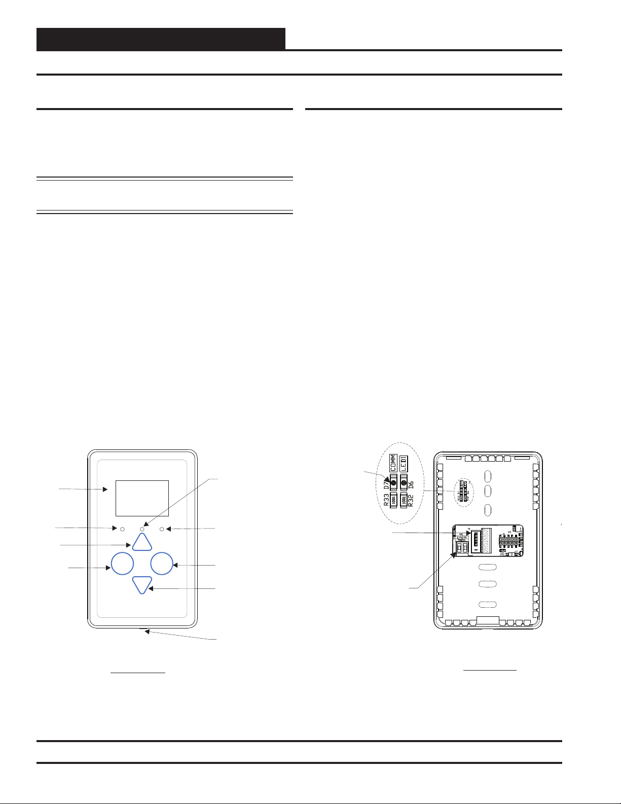
BASIC OPERATION.......................................................................................................................... 4
Sensor Operation ..................................................................................................................................................... 4
LED Operation ......................................................................................................................................................... 4
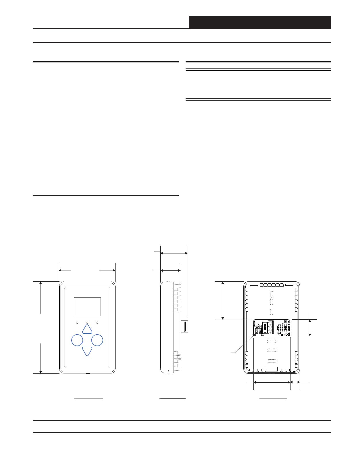
MOUNTING AND WIRING ................................................................................................................ 5
Dimensions .............................................................................................................................................................. 5
Environmental Requirements ................................................................................................................................... 5
Important Wiring Considerations .............................................................................................................................. 5
Mounting .................................................................................................................................................................. 5
SENSOR OPERATION ...................................................................................................................... 6
Main Sensor Display Screens....................................................................................................6
Temperature and Humidity Status Screen .......................................................................................................... 6
Outside Air Temperature Humidity Status Screen............................................................................................... 6
Unit Information Screen ...................................................................................................................................... 6
Setpoint Adjust Screen ....................................................................................................................................... 7
Operation Modes ................................................................................................................................................ 7
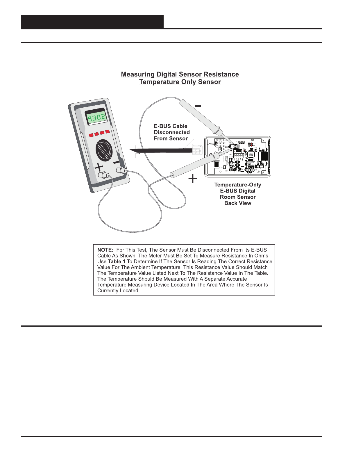
TROUBLESHOOTING....................................................................................................................... 8
Temperature Sensor Testing for the Temperature Only Sensor ............................................................................... 8
APPENDIX ..................................................................................................................................... 10
Sensor Confi guration and Test Screens ................................................................................................................ 10
Connecting the E-BUS Digital Room Sensor to the HVAC Unit Controller ............................................................ 12
Connecting a Wall Mounted E-BUS CO2 Sensor to the HVAC Unit Controller ...................................................... 13
Connecting the E-BUS Digital Room Sensor to the VAV/Zone Controller ............................................................. 14
Connecting a Remote Sensor ................................................................................................................................ 15
Mounting Plate Dimensions ................................................................................................................................... 18
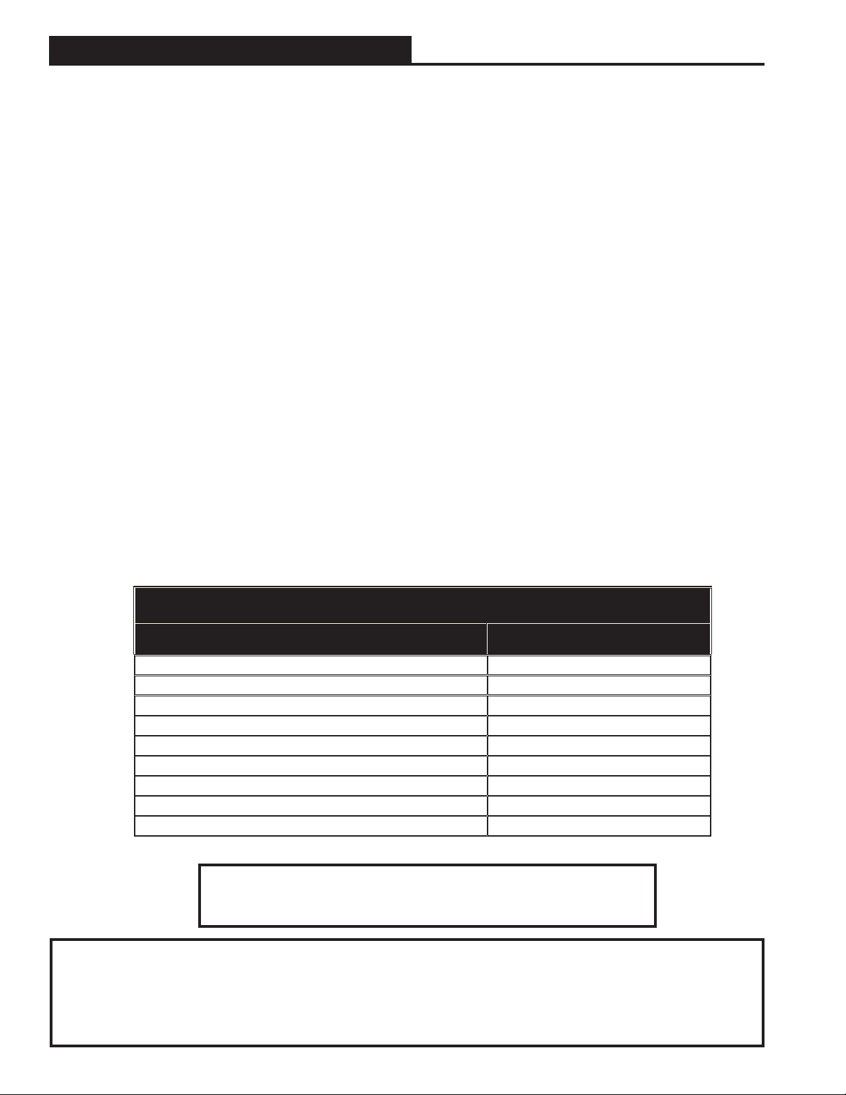
PART NUMBER CROSS REFERENCE TABLE
PART DESCRIPTION AAON P/N
E-BUS LCD Digital Room Sensor Temp Only ASM01819
E-BUS LCD Room Sensor Temp & Humidity ASM01820
E-BUS Digital Room Sensor Temp & Humidity (No Display) ASM02221
Wall-Mounted E-BUS CO2 Sensor ASM01829
Mounting Plate G026490
Return Air Duct Temperature Sensor - 12” P87140
VCCX2 Controller ASM01698
VCB-X Controller ASM01862
VAV/Zone Controller P.D. & P.I. ASM01627 / ASM01630
AAON, Inc.
2425 South Yukon Ave.
Tulsa, OK 74107-2728
www.aaon.com
Factory Technical Support Phone: 918-382-6450
Controls Support Phone: 866-918-1100
AAON Manual P/N: G042540, 01N
Copyright February 2019 AAON, Inc.
AAON, Inc. assumes no responsibility for errors or omissions.
This document is subject to change without notice.
This manual is also available for download from our
website—aaon.com—where you can always find the
latest literature updates.