Stulz C7000 User manual

OPERATING INSTRUCTIONS Index G57
Issue 6.2019
C7000
Original instructions
Microprocessor

EN/06.2019/G57 © STULZ GmbH – all rights reserved
C7000 INSTRUCTIONS FOR A/C UNITS
Editor
STULZ GmbH
Holsteiner Chaussee 283
22457 Hamburg
ABOUT STULZ
Since it was founded in 1947, the STULZ company has
evolved into one of the world’s leading system suppliers of
air-conditioning technology.
Since 1974 the group has seen continual international
expansion of its air conditioning technology business, spe-
cialising in A/C for data centres and telecommunications
installations.
STULZ has ten production plants (2 in Germany, Italy,
the USA, Great Britain, Spain, 2 in China, Brazil and India)
and twenty subsidiaries (in Germany, France, Italy, Great
Britain, Belgium, Brazil, the Netherlands, New Zealand,
Mexico, Austria, Poland, Spain, Singapore, China, India,
Indonesia, South Africa, Sweden, Australia and the USA).
The company also co-operates with sales and service
partners in over 140 other countries, and therefore boasts
an international network of air-conditioning specialists.

3© STULZ GmbH – all rights reserved EN/06.2019/G57
C7000 INSTRUCTIONS FOR A/C UNITS
Contents
1. Presentation of the system ............................................................................... 5
2. Operator interface ............................................................................................. 6
2.1 Operational elements - C7000IOC................................................................................. 6
2.2 Operational elements - C7000 Advanced.................................................................... 7
2.3 Operational elements - C7000 Display ......................................................................... 9
3. Controller start................................................................................................. 10
4. Info menus........................................................................................................ 16
4.1 Info commands - C7000.................................................................................................. 16
5. Configuration ................................................................................................... 34
5.1 Loading a new Software ................................................................................................... 36
5.2 Control commands - C7000........................................................................................... 37
5.3 Values...................................................................................................................................... 38
5.4 Components ......................................................................................................................... 58
5.4.1 Sensor........................................................................................................................... 58
5.4.2 Refrigerant circuit, Standard................................................................................. 61
5.4.3 Refrigerant circuit, optional components......................................................... 73
5.4.4 Cooling water circuit, internal components...................................................... 77
5.4.5 Cooling water circuit, external components .................................................... 84
5.4.6 Air circuit, internal standard components......................................................... 87
5.4.7 Air circuit, internal optional components........................................................... 98
5.4.8 Air circuit, external optional components ...................................................... 102
5.4.9 Auxiliary Ports ......................................................................................................... 103
5.5 Statistics.............................................................................................................................. 105
6. Special operation modes .............................................................................. 108
6.1 Week program................................................................................................................... 108
6.2 Zone control....................................................................................................................... 109
6.2.1 Sequencing.............................................................................................................. 114
6.2.2 CW Standby Management.................................................................................. 115
6.2.3 Zone for DFC control............................................................................................ 116
6.3 Ecocool................................................................................................................................ 121
6.4 Operation modes for CW2 units ................................................................................. 130
6.5 Differential pressure control......................................................................................... 133
6.6 Supply air pressure standby management (SAPSM) ........................................... 135
6.6.1 SAPSM and no supply air pressure control in case of sensor failure ... 140
6.7 Differential temperature control ................................................................................. 141
6.8 Summer-/winter operation........................................................................................... 145
6.9 Manual Operation............................................................................................................. 146
6.10 UPS operation................................................................................................................ 147
6.11 ACT - Adaptive Cooling Technology........................................................................ 148
6.12 Calculation of the Air Volume Flow .......................................................................... 149
6.13 Power indication............................................................................................................ 150
6.14 Control of a Uk24mod gateway............................................................................... 151
6.15 Special software option for CyberLab units......................................................... 153
Subject to technical modifications.

4EN/06.2019/G57 © STULZ GmbH – all rights reserved
C7000 INSTRUCTIONS FOR A/C UNITS
7. Bus communication....................................................................................... 154
7.1 System architecture with the C7000IOC ................................................................ 154
7.2 System architecture with the C7000AT................................................................... 155
7.3 Bus Layout ......................................................................................................................... 156
7.3.1 General...................................................................................................................... 156
7.3.2 Configuration of the IO bus................................................................................. 156
7.3.3 Preparation before Installation.......................................................................... 157
7.3.4 Setting the Bus Address...................................................................................... 157
7.3.5 Bus overview ........................................................................................................... 159
7.3.6 Special cases .......................................................................................................... 160
8. Alarm treatment............................................................................................. 163
8.1 Alarm display...................................................................................................................... 163
8.2 Alarm Reset........................................................................................................................ 163
8.3 Configuration of external and unit alarms................................................................ 164
8.4 Alarm texts.......................................................................................................................... 165
8.5 Alarm texts in the case of hardware errors .............................................................. 167
9. Troubleshooting............................................................................................. 168
10. Hardware components................................................................................ 170
10.1 I/O controller (C7000IOC)......................................................................................... 170
10.2 EDIO - extension board for digital in- and outputs............................................ 172
10.3 EAIO - extension board for analog in- and outputs........................................... 174
10.4 EBUS-extension board for RS485 bus ................................................................ 176
10.5 Driver module for electronic expansion valve EVD............................................ 177
10.6 C7000 Advanced - Terminal (C7000AT).............................................................. 178
10.6.1 Driver module....................................................................................................... 179
10.7 C7000 Display............................................................................................................... 180
11. Default configurations ................................................................................ 182
11.1 Preconfigurations ......................................................................................................... 196

5© STULZ GmbH – all rights reserved EN/06.2019/G57
C7000 INSTRUCTIONS FOR A/C UNITS
This manual is based on the software versions IOCV6.85 and ATV4.73.
The C7000 control system offers a maximum of
operating safety for industrial applications combined
with two versions for the operator interface. The
C7000IOC takes charge of the control in itself and
the optional C7000 Advanced serves as a comforta-
ble operator interface.
Each A/C unit has its own controller while all control-
lers can be linked together in a bus system.
Beyond the basic cooling functions, the C7000 con-
trol system provides some interesting features like an
intelligent management of high/low pressure-alarms,
a proportional fan speed control which opens a wide
spectrum of applications and time-based functions
like:
- week timer
- unit sequencing within definable unit groups
A watchdog on the IOC board monitors the CPU
function and produces a restart, as soon as for 0,5
seconds no CPU activity could be detected.
The core of the C7000 control system is the C7000
I/O controller on which up to 4 EAIO/EDIO for
additional in- and outputs can be perpendicularly
plugged.
The C7000 control systems manages 3 busses:
1. RS485 IO-bus for the communication among the
A/C units
2. RS485 BMS-bus for the communication with a
building management system
3.RS485 component bus (e.g. for EVD {driver mod-
ule for expansion valve}, µPC )
For service purposes like software download and
control via laptop a RS232 interface is located on the
I/O controller the same as on the C7000 Advanced.
1. Presentation of the system
IICBus: internal data bus in the IO controller
EAIO: Extension board for analog in- and outputs
EDIO: Extension board for digital in- and outputs
EBUS: Extension board for a RS485 bus
Analog (A) and digital (D) in- and outputs
AIN AOUT DIN DOUT
IOC 4 4 11 7
EAIO 4 4 / /
EDIO / / 8 6
Maximum equipment
IOC + 4 EAIO 20 20 11 7
IOC + 4 EDIO 4 4 43 31
Interfaces
IOC
1 RS485 IO bus, terminals
4 IICBus, SUBD15
EBUS connection SUBD15
RS232, SUBD9
EAIO IICBus, SUBD15
EDIO IICBus, SUBD15
EBUS
I/O controller connection SUBD15
RS485 BMS-bus, terminals
RS485 component bus, terminals
C7000AT 2 RS485 IO-bus + BMS, terminals
2 RS232 BMS + service, SUBD9

6
iobus
iobusok
sensor 1
comp 1
suctionv 1
gecwv 1
gvalve 1
drycool 1
pump 1
eheat 1
gasheat
pwwheat
humi 1
dehumi
fan 1
louver 1
equip
is 1
state
ups
wprg
event
log 1
option
exalarmin 1
zone 1
loaddefault dx1
EN/06.2019/G57 © STULZ GmbH – all rights reserved
C7000 INSTRUCTIONS FOR A/C UNITS
2. Operator interface
2.1 Operational elements - C7000IOC
The operational elements for the C7000IOC i.e. the
I/O controller consist of the keyboard of your PC
or laptop. You operate the C7000IOC by specified
commands which follow an easily comprehensible
syntax.
To establish the connection from your PC to the
C7000 you need a 9-line cable with SUBD 9 con-
nectors at both ends (crossed type), which can be
obtained as an option and a terminal program e.g
"C7000Serice".
Connect the cable at a serial port of your PC and at
the service port X15 on the IOC.
To prevent a destruction of electronical elements due
to potential differences, use a laptop with battery
supply when connecting the laptop to the C7000IOC
service port.
Start the terminal program.
If your PC is not equipped with a serial RS232 inter-
face, you may use a RS232USB converter.
You can now communicate with the connected
C7000IOC, in return the IOC sends the following
prompt to your PC:
"ioc ##:>", where ## represents the bus address.
The commands can be classified into three major categories:
1. bus specific control commands
2. commands related to A/C unit components
3. commands concerning the whole A/C unit
1. bus command 2. component command 3. A/C unit command
Each command displays a detailed help for further
parameters (if there are any) when it is followed by "h"
like e.g. "comp h".
A command of the second (component command) or
third category (unit comm.) which is typed in without
any parameters displays all the information about its
subject (except "loaddefault ###" which is an exe-
cution command).
The commands of the 2nd and 3rd category will be
largely explained in the context of the description of
the C7000 functions.
The iobus command edits the actually stored
IO-bus-configuration.
The commands on a lightgrey (yellow) background need
no further parameters. The commands which are followed
by a number need this number because there are several
components of the same type.

7© STULZ GmbH – all rights reserved EN/06.2019/G57
C7000 INSTRUCTIONS FOR A/C UNITS
This command is a control command and shows nei-
ther help nor information but execute the command
right after pressing the return/enter-key.
The counting of any digital or analog in- or output
begins with number 1. Despite this the digital/analog
in- or output 0 can be assigned to any component.
This will allow the component to stay part of the con-
figuration even if it does not take part in the control.
A double assignment of inputs and outputs is tech-
nically possible but only reasonable in exceptional
cases.
Outputs in the languages English and German are
available at the service port.
If within a command, where the input of a number is
expected, nothing is entered, the terminal program
interprets this as "0".
Whenever a parameter is expressed by a logi-
cal function, 0 means no, disabled, 1 means yes,
enabled.
If at unit start no valid configuration is found, a mini-
mum configuration is loaded.
Note that no year date below 2000 can be entered.
Selector key You can select menus and change parameters with the selector key
Confirmation key You acknowledge the functions/parameters selected with the selector key with the con-
firmation key.
Reset key Alarm signals are acknowledged with the reset key. Press it once to silence the
alarm tone. Press it a second time to clear the alarm message (if the cause has been
eliminated).
LED alarm This LED display flashes in the event of an alarm and remains lit after the reset key has
been pressed once.
LED start/stop This LED display lights up when at least one C7000IOC within the bus is switched on.
On/off key The control of the selected A/C unit is switched on/off with this key. If the on/off protec-
tion is enabled the control is switched on/off with a delay or after having entered a pass-
word (details on page 12).
Audible indicator The audible indicator issues an alarm tone when an alarm has occurred.
Display The display shows data, operating conditions and information for the operator's
guidance.
<> = Selector key
Ok = Confirmation key
Reset = Reset key
LED = Alarm
LED = On/off
= On/off key
Display
Audible indicator
2.2 Operational elements - C7000 Advanced

8EN/06.2019/G57 © STULZ GmbH – all rights reserved
C7000 INSTRUCTIONS FOR A/C UNITS
Operation - Navigation through the menus
The principal keys to navigate in and across the menus are the
selector key and the confirmation key, which have the function of the
mouse for a PC. The cursor, to keep the analogy with a PC, is repre-
sented by the inverse display of a field content. This field may contain
an expression, a number or a symbol.
There are two types of menus: Selection menus and parameter men-
us. In selection menus you can choose a menu point with the help
of the selector key and after having pressed the confirmation key it
will bring you to the next submenu. To get to the next menu on a level
above there is a "Return"-field in the top left corner of every menu.
In parameter menus, which represent the end of a menu branch,
you can select parameters with the selector key, but if you press the
confirmation key, the parameter is displayed black on a clear back-
ground with a black frame and indicates this way the change mode.
By the selector key you can change the parameter value. Pressing
the confirmation key finishes the modification and displays the cur-
sor inversely again. Below the smallest value appears the symbol of
an arrow to the left. If you select this arrow and press the confirma-
tion key, the enter mode of the parameter is left without modification
of this one.
Selection menu
Parameter menu
In a few parameter menus, there is the note "more" in the bottom frame line, which indicates that another win-
dow will be displayed after the last parameter. You can also reach this window by typing the selector key "<"
when the cursor is on the field "return".
Note:
After the C7000AT has displayed a submenu of an C7000IOC for 10 minutes without key activation, it will
show the main menu of the corresponding unit again.

9© STULZ GmbH – all rights reserved EN/06.2019/G57
C7000 INSTRUCTIONS FOR A/C UNITS
Reset key Alarm signals are acknowledged with the reset key. Press it once to silence the
alarm tone. Press it a second time to clear the alarm message (if the cause has been
eliminated).
LED alarm This LED display flashes in the event of an alarm and remains lit after the reset key has
been pressed once.
LED start/stop This LED display lights up when the control of the A/C unit is switched on.
Start/stop key The control of the A/C unit is switched on/off with this key.
Audible indicator The audible indicator issues an alarm tone when an alarm has occurred.
Display The display shows the actual temperature and humidity, operating states and alarms.
Display
Audible indicator
Cooling
Heating
Humidification
Dehumidification
Request sent
Actual temperature
Actual humidity
Alarm
Response received
The status request is sent to the C7000IOC in a
fixed cycle of 3 seconds. During the request the
symbol is displayed.
As soon as a formally correct response is recei-
ved the following symbol flashes once.
If no response has been received after three
consecutive requests, question marks are dis-
played instead of the temperature and humidity.
Display with the control switched off:
2.3 Operational elements - C7000 Display
Reset = Reset key
LED = Alarm
LED = On/off
= On/off key

10
= OK
EN/06.2019/G57 © STULZ GmbH – all rights reserved
C7000 INSTRUCTIONS FOR A/C UNITS
3. Controller start
C7000AT
After having switched on the pow-
er supply of the C7000AT the bus
overview will appear.
With the selector key you can
choose the unit which you want to
control.
A symbol/unit which is selected, is
displayed inversely.
Empty bus positions will be skipped.
When you have selected a
C7000IOC and confirmed by the
OK key, the main menu for the
C7000IOC is displayed.
When you have selected a C7000AT
and confirmed by the OK key, after
having entered the AT password
the main menu for the C7000AT is
displayed.
Confirmation view
Main menu for C7000IOC
Main menu C7000AT
After having marked the last bus
participant position (bus address 14
in the example) you get to the fol-
lowing display, with the selector key,
where all units are marked.
In this state you can switch on/off
the whole system by the local on/
off key.
Commands
state start
state stop
The control/the A/C unit is started.
The control/the A/C unit is stopped.
If some units are in operation, all units are switched off if you press the on/off key.
(Details see on/off protection, on the next page but one).
If you press the OK-button when all positions are marked the existing configuration is confirmed after the request
and entry of the AT-password.

11
>
>
© STULZ GmbH – all rights reserved EN/06.2019/G57
C7000 INSTRUCTIONS FOR A/C UNITS
Placement view
By pressing the selector key ">"
you come to the following window
in which the box "my own bus-ID is
marked.
After the confirmation of this window
by "OK" followed by the AT-password
the placement view is displayed.
In this window you can shift the
C7000AT, from which you operate
the system (ME) to another position
with the selector key.
By this you modify the bus address.
(MEold at position 0 and MEnew at
position 17)
Confirm the position by the
"OK-button".
Finally you can adjust the time and
date by selecting the clock in the
lower right corner.
The following items can be adjusted in sequence:
- Year, Month, Day, Hour, Minute, Second.
All active bus participants synchronize their time to this setting.
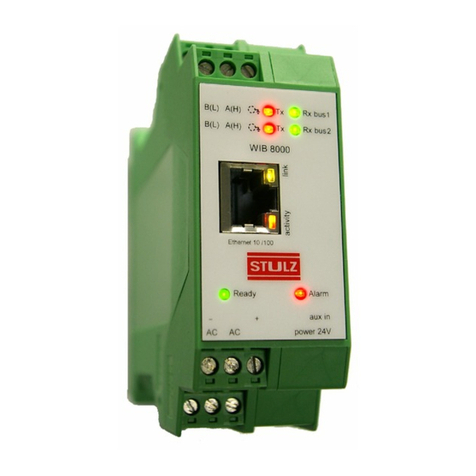
If a WIB8000, in which the time synchronization is enabled, is part of the Stulz bus, all connected C7000ATs and
C7000IOCs (by means of E-bus board) take over date and time of the WIB. This also applies to C7000ATs con-
nected via an IO bus with an C7000IOC, which is connected with the WIB by an E-bus board.

12 EN/06.2019/G57 © STULZ GmbH – all rights reserved
C7000 INSTRUCTIONS FOR A/C UNITS
1. In the BMS menu you can adjust the global address of the
C7000AT, and an available interface on the C7000AT which can be
either RS232 or RS485 the same as the protocol and, if applicable,
one of several data point lists according to the BMS requirement.
You have further possibilities to adapt the system to the BMS by the
menu points „Handshake“ and „Baudrate“. For further information,
see BMS manual.
2. Here you can set the alarm delay for the bus alarm, which will be
generated when the bus is interrupted.
3. In the system menu you can switch on (-1-) or off the alarm buzzer.
Further you can adjust the buzzer pitch.
Menu item "Temp. unit" allows you to choose between degree Fahren-
heit or degree Celsius.
In the menu item languages you can adjust the operator language.
The info submenu simply displays the software version of the
C7000AT.
In menu item "backlight" you can choose between "on" (in this case
the light remains lit permanently) and "auto", here the light is switched
out automatically 10 minutes after the last key activation. With the
first key activation the light is switched on again.
In the menu item "Password" you can set the AT password.
For the menu item "On/Off protection exist three possibilities:
1. Off, 2. Delay, 3. Password.
If you select the C7000AT for
further adjustments and confirm
with OK you will receive after hav-
ing entered the AT password the
following display with the menu
ramification as shown below:
Main menu for a C7000AT
With the first setting (off) the control is instantly switched on/off by the on/off key of the controller.
With the second setting (delay) the window shown beside appears after the on/off key has been pressed. A grey
bar diminishes from right to left within 3 seconds. During this time the key must be kept pressed, otherwise the
switching operation will not be executed.

13
}
© STULZ GmbH – all rights reserved EN/06.2019/G57
C7000 INSTRUCTIONS FOR A/C UNITS
If you select a C7000IOC you will receive the main menu as shown right
with the possibility to choose one of the three submenus "Info", "Opera-
te" or "Config".
In the middle of the window the control type (Room or supply air) is dis-
played and the actual values (Room or Supply air) below.
Below the actual values a symbol indicates, whether the unit runs in day
or night operation. Day operation corresponds to operation at the first
temperature setpoint. Night operation corresponds to operation at the
second setpoint.
Day operation Night operation
Further Symbols
This symbols lights up, when the controller has switched over to
winter operation. At summer operation the symbol is not visible.
This symbols lights up, when a voltage is detected at the input for
UPS operation or if UPS operation is requested by a BMS.
This symbols lights up, when the maintenance interval which can
be adjusted in the config menu is expired.
Main menu for a C7000IOC
Alarm symbol Bus address Time
Alarm text
Stop cause
Stop symbol
Unit name
Global address
Menu line
Control mode
Temperature
Main function
Humidity
Maintenance symbol
UPS operation
Winter operation
Day/Night operation
With the third setting (password) the operate password is requested when the on/off key is pressed. Having
entered the correct password the switching operation will be executed.

14 EN/06.2019/G57 © STULZ GmbH – all rights reserved
C7000 INSTRUCTIONS FOR A/C UNITS
Stop causes
The C7000IOC can be stopped by several functions or devices, which are displayed on the
C7000AT.
This symbol indicates, that the C7000IOC has been stopped.
The following symbols show the cause of the unit stop.
stopped by remote On/Off (remote switch connected to digital input)
stopped by BMS/WIB
stopped by WIB sequencing
(depending on the setting in the WIB)
stopped by internal timer (week program)
stopped by the on/off-key at the C7000AT or by the command "state stop" via the
C7000IOC service port.
stopped by the sequencing
stopped by fire alarm
Symbols for operating states
When the control is in operation, the following symbols indicate the unit status on the main
menu. These symbols are not displayed in the submenus.
Cooling, the cooling mode (DX, CW, FC, EFC, MIX)
is shown in the right top.
Heating
Humidification
Dehumidification
Symbols for alarm messages
When an alarm has occurred the following symbol is displayed in the left bottom corner.
Parameter values
Instead of numerical values two other displays are possible:
1. ??? - value requested at the C7000IOC, without response yet
2. XXX - component not configured

15© STULZ GmbH – all rights reserved EN/06.2019/G57
C7000 INSTRUCTIONS FOR A/C UNITS
To access the Operate level, the Config level
and the C7000AT main menu a password is
required.
There are 3 passwords in total, a user-spe-
cific password for the Operate level, the
Config level and the C7000AT menu each.
The passwords can be modified and are set
"0000" at the delivery.
Entering the password
The digits can be modified by the selector
key, after you have pressed the confirmation
key. After the digit adjustment confirm with
the confirmation key and pass over to the
next digit with the selector key ">".
When you have reached the last digit at
the right, you access the main menu of the
Operate resp. Config level by activating the
selector key ">" (if the password was right).
There is no limitation for the number of
attempts.
Passwords
The passwords for the "operate" and "config" level are saved on the C7000IOC board. So it is possible for exam-
ple to adjust the "operate" password "1234" for a C7000IOC with bus address 3 and the "operate" password
"5678" for a C7000IOC with bus address 5.

16 EN/06.2019/G57 © STULZ GmbH – all rights reserved
C7000 INSTRUCTIONS FOR A/C UNITS
4. Info menus
4.1 Info commands - C7000
Each component- or A/C unit command which is entered without parameters only displays information
without changing adjustments. However, the following commands give a general overview about the unit state
and configuration.
equip - shows the components and its number, also the extension cards (dig/ana)
state - shows the unit- and functional (cooling, heating etc.) runtimes and the unit/component state
is 1 - - setpoints, actual zone/unit values, limit values
is 2 - - alarm delay, priority, common alarm assignment for each limit value alarm
is 3 - - control type, sensor limitation values, cooling priority, winter operation, ups mode, outside temp.
for
condensation pressure reduction, gradient for press. reduction, winter start delay, bus/global
address,
temperature difference for overload activation, last service, service interval,
- assignment of in/outputs: common alarm, winter operation, remote on/off, ups operation,
actual temp./humidity, CW cooling off
wprg - shows the programmed timer function for the week (week program)
events - shows all registered events (maximum 200, alarms & unit on/off)
event 1 Prints the last events from number 1 to 20
event 2 Prints the last events from number 21 to 40
:
event 10 Prints the last events from number 181 to 200
event 20.07.2007 Prints all events of this date
event comp Prints all events which contain the expression „comp“
event clear Erases the event memory
event 1 13 Prints the events from number 1 to 13
ups - shows the ups (uninterrupted power supply) configuration
water - shows all settings concerning the water alarm.
fire - shows all settings concerning the fire alarm.
phase - shows all settings concerning the phase alarm.
flow - shows all settings concerning the water flow alarm.
service - shows all settings concerning the service alarm.
ain - shows the assignment of the analog inputs.
aout - shows the assignment of the analog outputs.
din - shows the assignment of the digital inputs.
dout - shows the assignment of the digital outputs.
option - Shows all information about activated special software options
e.g.: 002. Restart after fire (active)
option all Shows all possible special software options
001. OTE
002. Restart after fire
003. automatic alarm reset after limit value excess
004. SATS
When the fire alarm has ended the controller switches to
the state, in which it has been before the alarm occured e.g.
sequencing stop.

17© STULZ GmbH – all rights reserved EN/06.2019/G57
C7000 INSTRUCTIONS FOR A/C UNITS
The info- and control menus display only the components, sensors, unit and auxiliairy alarms, which are con-
figured in the config menu. This concerns the selection menus also. If e.g. no heating is configured the menu
item "heating" in the menus "Info/components" and "Control/components" does not appear. If no zone is
configured, this menu item is omitted in the menus "Info" and "Control". The runtime menus are reduced corre-
spondingly under "Info/statistics/runtimes".
The Info menus for an A/C unit, version
A equipped with a room air T/H sensor
and one auxiliairy alarm, which does not
belong to a zone, reduce themselves as
shown beside.
Further on in this manual, the menus
appear in full view so that all menu items
can be explained.
Indication in the Info- and Control menus depending on configuration
As the C7000AT menu structure takes into account the requirements of different unit types, there are many
menus which are relevant only for special applications.
1. Chiller -
2. DFC control -
3. DFC² control -
4. CyberSonic -
When chiller specific menu items appear, they are faded out by a grey background in this
manual. For the chiller software a separate manual (Index G57D) exists.
Specific menu items are designated but not described in detail. For DFC control a sepa-
rate manual (G57B) exists.
The relevant menu items are mostly located in separate menus (named AE control), which
are not displayed here. When specific menu items appear, they are faded out by a grey
background in this manual. For DFC² control a separate manual (Index G17A, 18AA)
exists.
A detailed description can be found in the CyberSonic manual (Index G85).
005. CPP: commutation in case of flow alarm
006. ACT
007. Supply air pressure standby management
008. CyberLab described in chapter 6.15
option 3 1 Activates special software option number 3
option 3 0 Deactivates special software option number 3

18
Info
.../Humidity
.../Humidity/more
.../Temperature
.../Temperature/more
EN/06.2019/G57 © STULZ GmbH – all rights reserved
C7000 INSTRUCTIONS FOR A/C UNITS
The values of the relative humidity are displayed in this window.
1. The value, which is used for the control. It can also be a zone humidity.
2. Setpoint of the relative humidity
3. Shifted setpoint (caused by external setpoint setting or limitating control)
4. The actual value of the room humidity sensor.
5. The actual value of the supply air humidity sensor (if existant).
1. The actual value of the outside moisture content sensor (if existant).
2. The actual value of the specific humidity.
3. The setpoint of the specific humidity.
Values
Air
This window shows the following temperatures:
1. The value, which is used for the control. It can also be a zone temperature.
These values represent an average value for each parameter, which is calcu-
lated of all sensors of the units which are assigned to the same zone.
2. The adjusted setpoint (setpoint 1/ setpoint 2)
3. The setpoint shifted by the controller, the unit is controlled according to this
parameter only. This value corresponds to the adjusted setpoint in most
cases.
It may be different in the following cases by:
- week program - external setpoint shifting
- emergency operation - limitating control
- integral factor
4. The actual value of the room temperature sensor.
5. The actual value of the supply air temperature sensor.
6. The outside temperature
The following values are only shown for the CyberRow unit series.
Three room air and supply air temperatures each are measured in different
heights where each room/supply air sensor pair is assigned to a different fan.
These values are used for the differential temperature control od the fan.
The average of the 3 room temperatures is displayed in the top menu in line 4,
the average of the 3 supply temperatures in line 5.

19
Info
...Water/Temperature
...Air/Pressure
...Air/Humidity/more/more
© STULZ GmbH – all rights reserved EN/06.2019/G57
C7000 INSTRUCTIONS FOR A/C UNITS
In this window the actual value and the setpoint for the differential pressure of
the supply air (pressure gain in contrast to the room air pressure) in the raised
floor or cold aisle compartment is indicated.
The actual value and the setpoint for the room air pressure, which are displayed
in the lower part, is measured as differential pressure between the room and
the external pressure.
(part of DFC² control)
1. actual dew point
2. dew point of the setpoints (temperature and humidity)
You find a detailed description in chapter 5.4.6 in the description of humidifi-
cation and dew point control.
Values
Here the measured values of the cooling water circuits 1 and 2 are displayed.
1.Water temperature at the inlet, circuit 1
2.Water temperature at the outlet, circuit 1
3.Water temperature at the inlet, circuit 2
4.Water temperature at the outlet, circuit 2
Further menu only relevant for the chiller.
To display the water volume flow the A/C unit must be equipped with volume
measuring device.
The water volume flow sensor must be configured with the sensor purpose „50
- water volume flow“.
To display the water volume flow for example in the second water circuit (in the
menu "waterflow 2") of a CW2 A/C unit the water volume flow sensor must be
configured with the sensor purpose „53 - water volume flow 2“.
To display a third water volume flow for example through the hot water reheat
(in the menu "waterflow 3") the water volume flow sensor must be configured
with the sensor purpose „54 - water volume flow 3“.
.../Water

20
Info
...Refrigerant
...misc. data
...misc. data/more
...AE operation
EN/06.2019/G57 © STULZ GmbH – all rights reserved
C7000 INSTRUCTIONS FOR A/C UNITS
Here the measured values of the refrigerant circuits 1 and 2 are displayed.
1.Condensation pressure used for G valve, HP management
2.Hotgas temperature
3.Evaporation pressure used for LP management
4.Suction gas temperature
5.Suction gas pressure
Here the temperature of a freely adjustable sensor is shown.
This value does not influence the control and is only displayed for information.
The other values are only relevant for the chiller.
This menu is valid for units with enabled DFC² control. For historical reasons
the DFC² control is still designated by "AE-control" in this menu.
In the top line the operation mode (freeze protection, free cooling, mix mode,
summer mode) of the DFC² control is displayed. In the lower line the reason
for which summer mode has been forced is indicated. This can happen when
certain alarms have been released or when a digital input is set. The summer
operation which has not been caused by alarms but by the excess of the outsi-
de temperature limit, is not indicated here.
You find background information to the values displayed here in chapter 6.13.
Values
Other manuals for C7000
1
Table of contents
Other Stulz Computer Hardware manuals
Popular Computer Hardware manuals by other brands

Harbor Freight Tools
Harbor Freight Tools LUBRICATOR 40312 Assembly and operating instructions

Commell
Commell FS-A79 user manual

Bang & Olufsen
Bang & Olufsen BeoSystem 1 Guide

Texas Instruments
Texas Instruments INA234EVM user guide

Quanmax
Quanmax KUBE-8040 user guide

WEG
WEG EXP-IO1-ADL500 installation manual