DRY Series 500 Installation, Operation and Maintenance Manual
6 (April 2017)
2.0 INSTALLATION
2.1 Receipt of the Unit
Upon receiving the DESICAiR desiccant
dehumidification unit, immediately inspect the
unit for damage which may have occurred
during shipment. Carefully remove the shipping
cover and protective packaging. Remove the top
access panel. If any damage is found, report it to
the carrier immediately. Any obvious damage
incurred during shipping must be noted on
the freight carrier’s delivery forms BEFORE
signing for the equipment. Freight claims
must be done through the freight carrier.
Generally, all equipment ships “F.O.B. Factory”.
STULZ can assist in the claim filing process with
the freight company.
Remove any loose parts, and check the
equipment against the packing list to see if the
shipment is complete. Report all discrepancies
to the appropriate authority.
2.2 System Location and Clearance
The dehumidifier is designed to be operated in a
level position. Choose a location convenient to
the area to be dehumidified. Allow enough room
around the dehumidification system to access
controls, gauges, dampers, stowage area, etc.
Recommended minimum clearances on all sides
of the unit are 1x the full width of the cabinet.
The reactivation discharge air
can be very warm and humid. Keep items that
may be damaged by excessive heat and
humidity away from the reactivation air outlet.
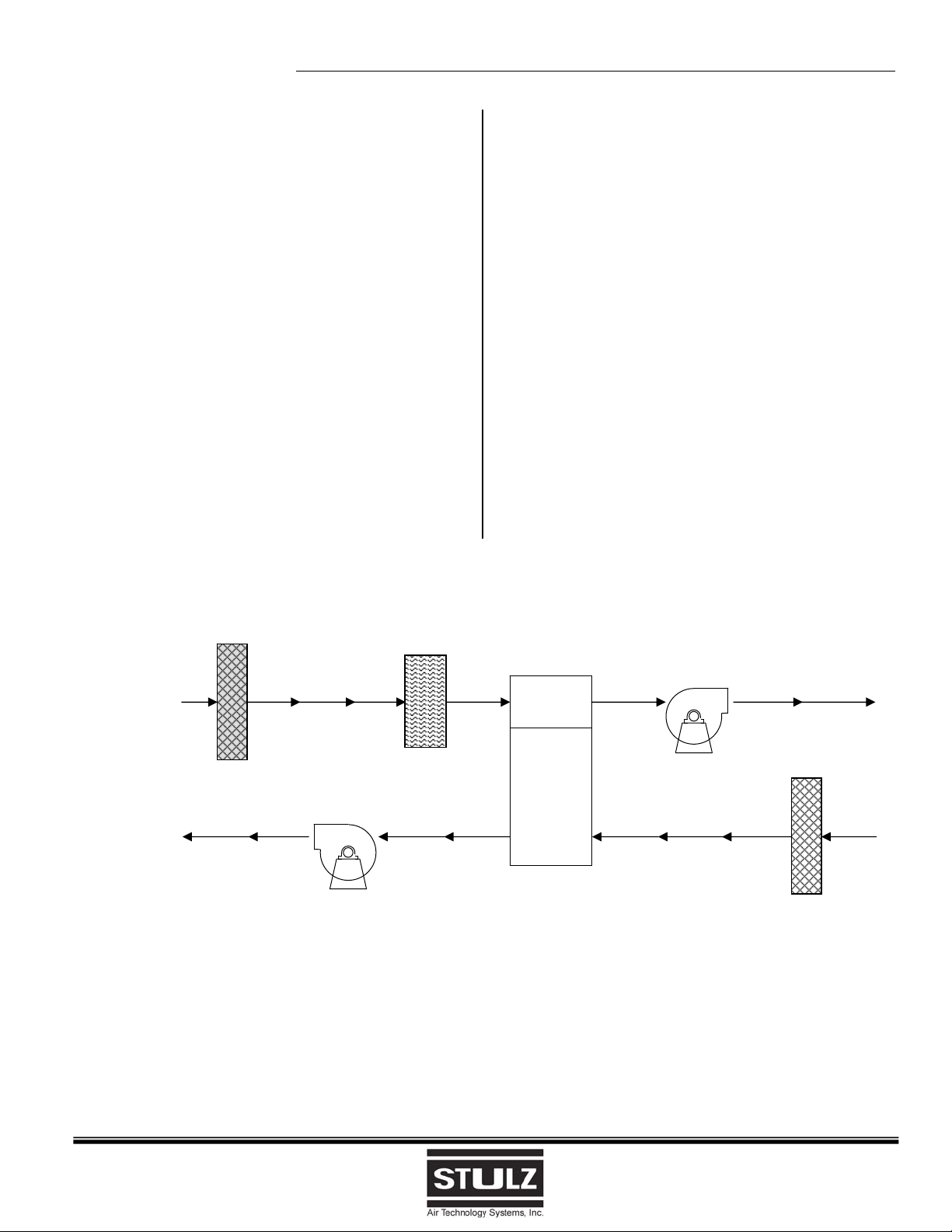
The “process” and “reactivation” inlet and outlet
openings are located on the ends of the unit as
shown on the Installation drawing.
To judge the clearance requirements, consider
that all the components are housed inside the
DESICAiR dehumidifier cabinet. The rotor is
typically the largest of the components that may
need removal. Blower assemblies, while
somewhat smaller, also require sufficient
clearance for removal.
Position the unit in the desired location. Make
sure the mounting surface is able to support the
weight of the equipment and keep it level. The
following general requirements should also be
considered:
1) The power source should be located as near
as possible to the installed location of the
equipment.
2) The power source wiring should include a
main power disconnect switch. If the unit is
purchased from STULZ without an optional
power disconnect switch, one should be
provided by the installer. Provisions should
be made to ensure power is not accidentally
disconnected during normal operation and
the main disconnect switch is not used
instead of the mode selector switch to turn
the system off for normal shut-down.
3) If possible, avoid locations where the air
intakes will be laden with dust, dirt, soot,
smoke, or other debris.
4) DO NOT operate the unit in or near
flammable or corrosive environments or
allow flammable or corrosive air into the unit.
5) Refer to the wiring diagram provided with
your unit for the proper electrical
connections.
2.3 Connecting Ductwork
Ducting should be sized for the appropriate air
quantity and pressure drop. The clearance
required for the duct connections depends on
whether the unit is to be ducted for process air,
reactivation air, or both.
When installing a unit outside the conditioned
space, the process inlet and outlet must be
ducted to and from the conditioned space to
prevent humid air from entering the process air
stream.
The reactivation air temperature at the outlet will
be warm (approximately 130º F) and humid.
When installing a unit in the conditioned space,
the reactivation inlet and outlet must be ducted
to and from another area to prevent the warm,
moist air from being returned to the conditioned
space. If duct work is connected to the
reactivation outlet, it should be insulated and
sloped down and away from the unit. This will
prevent condensed moisture from accumulating
at the reactivation outlet.
Refer to the Installation drawing provided with
your unit for the duct connection sizes and
locations.