Sturtevant Richmont TCV-Ethernet User manual
Sturtevant Richmont
Local Reach. Global Support.
Division of Ryeson Corp.
3203 N. Wolf Road
Franklin Park, IL 60131
Phones: 847/455-8677 800/877-1347
Fax: 847/455-0347
Web Site: www.srtorque.com
E-Mail: [email protected]
TCV-Ethernet Operating Manual
(Product P/N 10469)
Manual P/N 857274

Page 1
Table of Contents
Section Page
Warnings and Cautions . . . . . . . . . . . . . . . . . . . . . . . . . . . . . . . . . . . . . . . . . . . . . . . . . . .1
Introduction . . . . . . . . . . . . . . . . . . . . . . . . . . . . . . . . . . . . . . . . . . . . . . . . . . . . . . . . . . . .3
Installation . . . . . . . . . . . . . . . . . . . . . . . . . . . . . . . . . . . . . . . . . . . . . . . . . . . . . . . . . . . .5
Front Panel Operations / Programming / Bar Code Use . . . . . . . . . . . . . . . . . . . . . . . . . . .9
Wrench Communications . . . . . . . . . . . . . . . . . . . . . . . . . . . . . . . . . . . . . . . . . . . . . . . .28
Ethernet Functionality . . . . . . . . . . . . . . . . . . . . . . . . . . . . . . . . . . . . . . . . . . . . . . . . . . .29
Dimensions . . . . . . . . . . . . . . . . . . . . . . . . . . . . . . . . . . . . . . . . . . . . . . . . . . . . . . . . . . .30
Warnings
There is a high electrical voltage inside the unit that could cause electric shock.
Do not allow any type of liquid to come into contact with any part of the unit.
Immediately discontinue use of the unit if smoke, an abnormal odor, or an unusual
sound is emitted by the unit.
Do not fold, bend or apply excessive force to any cables or fittings.
Cautions
•The AC power entry can be configured to accept 110VAC or 220 VAC electric power. Before
supplying power to the unit ensure that the voltage selection is correct for the actual power
being supplied.
•Avoid installing or storing this unit in a location where it may become wet or dust covered.
•Do not mount or place this unit in an unstable location.
•Dropping this unit may result in personal injury or damage to the unit.

Page 2
•Turn the unit off and remove electric power plug before performing any maintenance on the
unit.
•There are no user serviceable parts inside the main enclosure of the unit.
Page 3
Introduction
The TCV-Ethernet and SLTC-FM Switch Wrench are an integrated torque control and data
management/communications system. The system is designed for high speed, high volume
assembly operations using Ethernet communications running the PowerFocus open protocol.
Tool communications are performed using frequencies the 2.4GHz band. Primary upstream
communication is via the supplied Ethernet connector; other communications are through an
I/O port, RS-232 port, and liquid crystal display.
The TCV-Ethernet is essentially two communications systems working together. The TCV
(Torque Control Verifier) function receves and processes communications with the Switch
Wrench programmed into the unit as the current working tool. The information gathered by the
TCV is communicated to the Ethernet interface, which handles primary upstream communica-
tions to the plant floor control system. As fasteners are tightened, they are reported to the TCV
by the torque wrench. As events (individual tightenings or batch completions) occur, the
Ethernet side of the unit encodes the information using the PowerFocus Open Protocol and
transmits it via the Ethernet connection.
We recommend that purchasers and users read this manual thoroughly. If this unit is mishan-
dled, bodily injury or damage to the unit may occur.
This manual is a general guide to the operation of the TCV-Ethernet unit. If any additional ques-
tions arise, please contact your sales representative.
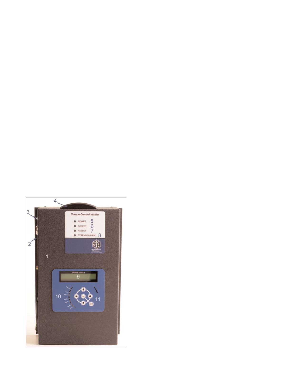
1. Case
2. Mounting Flange (left and right sides)
3. Mounting Holes (4 total - 2 per side)
4. Antenna Cover
5. Power LED
6. Accept LED
7. Reject LED
8. Strength/Programming LED
9. 2-Line LCD Screen
10. Ethernet Status Indicators
11. Programming Keypad
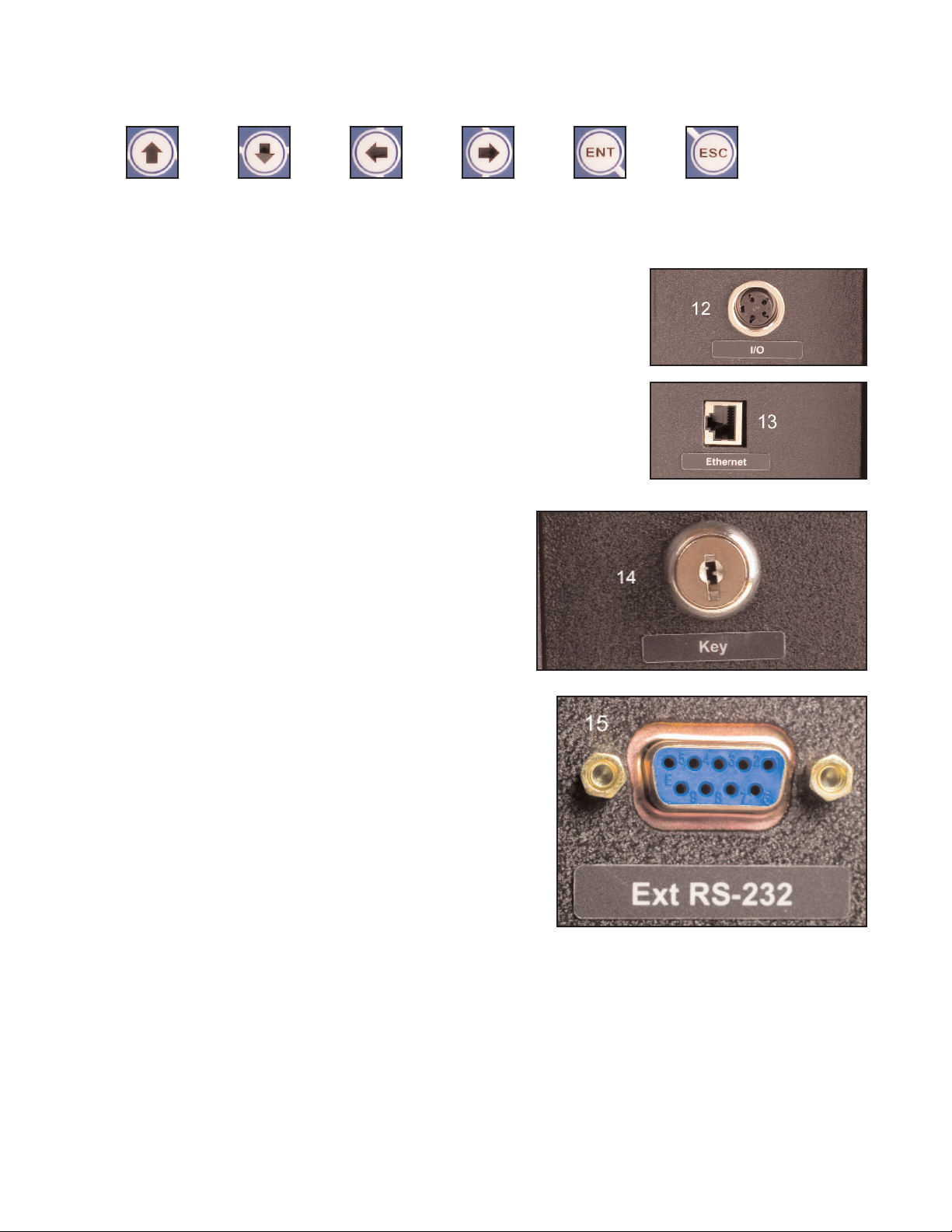
Up Down Left Right Enter Escape
12. I/O Connector (Relay Connector)
13. Ethernet Connector
14. Keyed Lock
The keyed lock is used to tie a specific torque
wrench transmitter to the unit.
15. 9-Pin DSUB Connector
Page 4
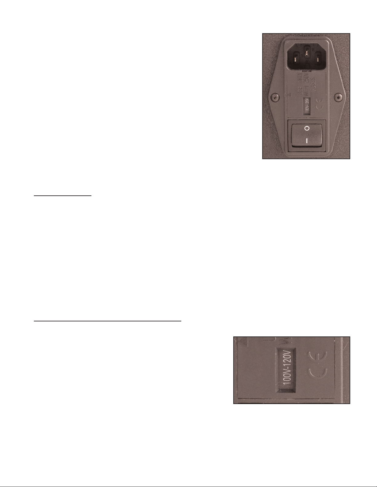
16. Power Entry Module
The Power Entry Module (PEM) performs power management
and electrical safety functions.
There are several components to the Power Entry Module.
These include a power cord receptacle, a power switch, a
fuse holder and a power selector. The current setting for the
power selector shows through a window just above the power
switch.
See the installation section for critical information prior to
installing the unit.
Installation
Considerations
The following factors should be taken into consideration when selecting the installation location:
•The unit must be mounted in a location that is physically stable.
•The location must be such that the unit can be attached to it via fasteners passing
through the mounting holes in the case flange.
•The location must protect the unit from contact with water and excessive dust.
•The unit requires electric power of 120VAC or 240 VAC.
•There should be sufficient room on either side of the unit to provide access for connect-
ing communications and maintaining the unit.
•The front of the unit should be readily visible and readily accessible.
• The unit must be mounted within reliable transmission distance from the loation where
the FM Switch Wrench tied to the unit will be used.
Power Entry Module Voltage Selection
It is imperative that the Power Entry Module be set for the voltage to be used to power the unit
before electric power is connected to the unit.
The Power Entry Module (PEM) has a window just above
the power switch that shows the present setting for the volt-
age selector. The selector will show either “100V-120V” or
“220V-240V” through the window. In the image to the right,
the internal voltage selector is set for 120VAC power.
If the voltage selection visible to through the window is the
voltage that will be used to power the unit, installation can proceed. If the setting does not
match the power that will be used, the voltage selector must be changed to the correct, match-
ing setting.
Page 5
Page 6
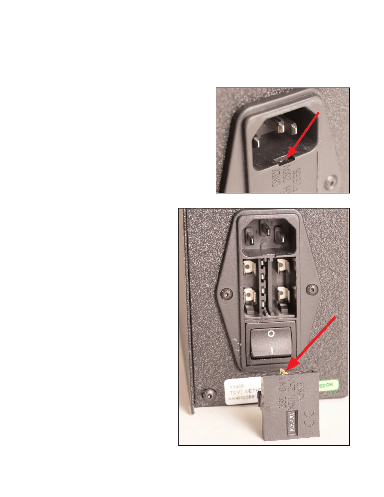
To change the voltage selection:
1. Make certain that the power cord is disconnected from the receptacle on the unit.
2. Set the unit on a flat work surface.
3. The voltage selector is attached to the plastic
cover that has the window through which the
current voltage selection is displayed. This cover
is a “snap-in” or press-fit type; it is pressed into a
recess in the PEM. The cover must be removed
to access the voltage selector.
To remove the cover, insert a fingernail or small
screwdriver into the slot located in the power
receptacle behind the tab at the top of the cover
and pry outwards gently. See photograph at
right.
4. The photograph to the right shows
the voltage selector holder removed
from the PEM. The current setting is
for 120VAC, as shown in the holder
window.
The voltage selector itself is a yellow
and black plastic and metal compo-
nent, one corner of which is visible
and highlighted by the red arrow.
Page 7
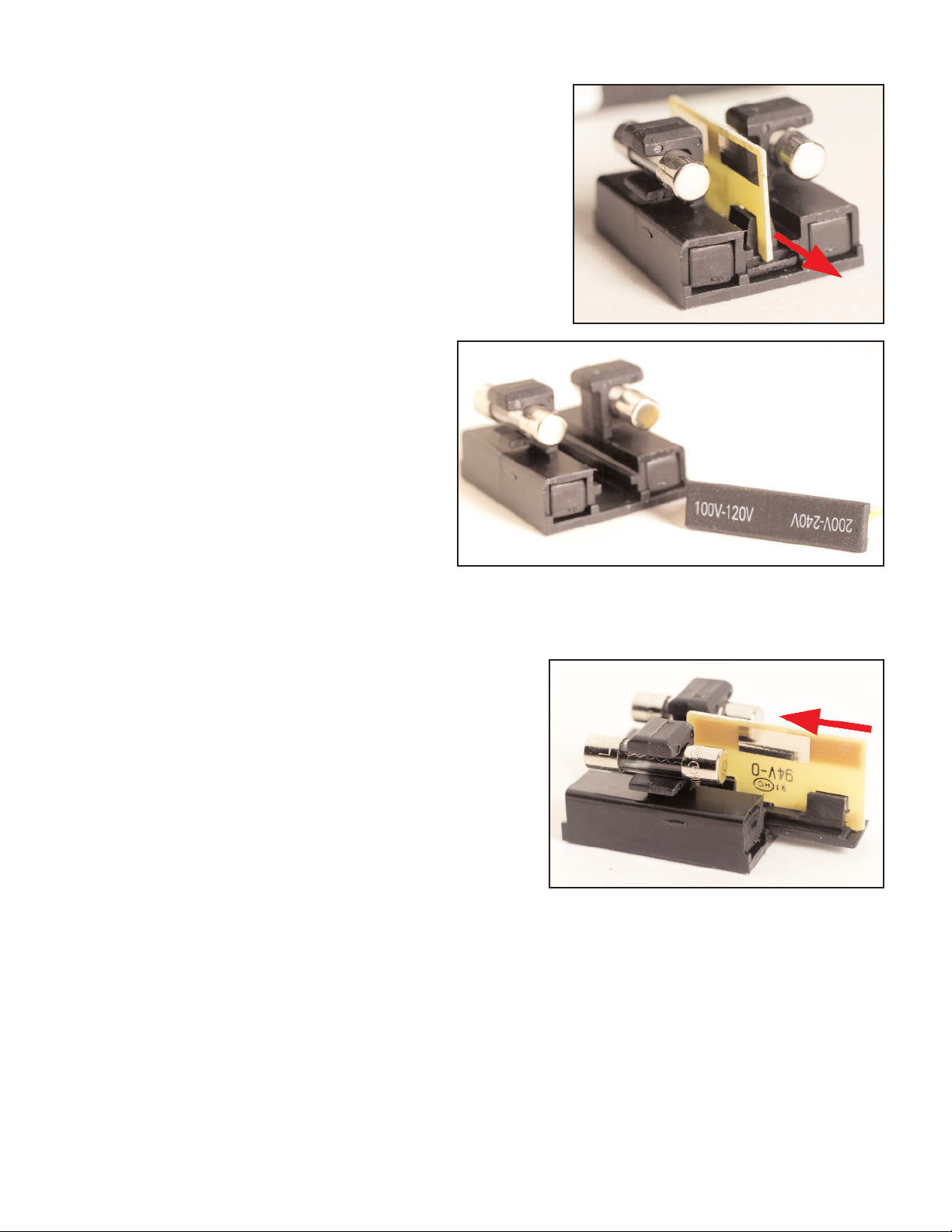
5. The voltage selector fits in a slide in the middle of
the holder. To remove the voltage selector from the
holder, simply slide it out of the channel in which it
fits.
6. When the voltage selector has been
removed, tilt it so it is oriented as
shown in the image to right. The end
that is closest to the holder and has
the top of the letters at the top is the
voltage for which the unit was set. To
change the voltage, reverse the ori-
entation of the selector so the
required voltage will be the end that
is at the bottom of the slot when the
selector is reinserted. This change of
orientation establishes the voltage setting change when the selector is reinserted.
7. Reinsert the voltage selector in the holder with
the end marked for the required voltage entering
the slot first.
8. Reinsert holder into PEM.
9. Check the voltage selector window to insure that the correct voltage now shows through
the window. If the correct voltage is displayed, the process has been properly performed.
Page 8
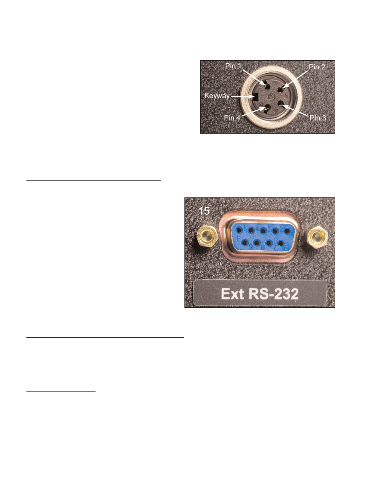
Four-Pin I/O Port Connection
This is a four-pin circular connector, Amphenol-Tuchel T3303 000. The relay pin connection
configuration is:
Pin 1 Cycle OK
Pin 2 Batch Complete
Pin 3 Cycle Reject
Pin 4 +24VDC
The unit arrives with +24VDC electric power supplied
on Pin 4. The system power at Pin 4 is rated at
+24VDC and 0.5 Amps. The voltage on Pin 4 will be
returned on pins 1 - 3 as the corresponding relays close.
RS-232 Nine-Pin DSUB Connection
This connector is used to communicate with an
external computer. There is software available
that permits programming the TCV-Ethernet via
serial communications through this port.
A null-Modem cable (or convertor and standard
cable) is required to connect this port to another
device.
For this connector:
Pin 2 - RX
Pin 3 - TX
Pin 5 - GND
The other pins are straight-through connections.
Ethernet Connection (RJ45 - 10BASE - T)
This port is used for connection to the plant floor control ethernet network. This unit will transmit
TCP/IP messages based on the PowerFocus Open Protocol directly to the plant floor system
each time a fastnening is communicated to the unit by the FM Switch Wrench.
Power Connection
Check the voltage selection to assure the voltage setting for the unit is the same as that being
supplied. If the two voltages match, connect the power cord to the power receptacle in the
Power Entry module.
Page 9
Front Panel Operation and Programming
The front panel provides immediate access to current TCV-side and wrench communications
status and access to programming TCV functions and Ethernet communications.
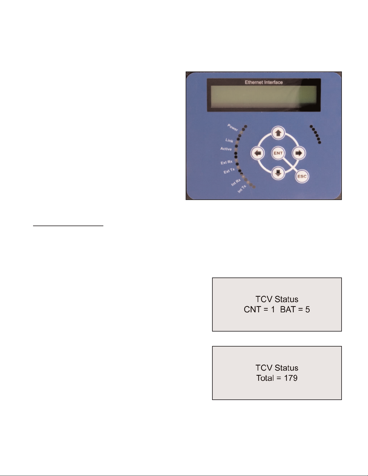
Status checks and programming communica-
tions and functions are performed through the
front panel display and buttons. The two-line
liquid crystal display provides information to
the programmer on current status, current
menu options, and the options selected.
Menu navigation and function selection is per-
formed using the six buttons provided: Up,
Down, Left, Right, Enter, and Escape.
When the unit is turned on (activated), it initial-
ly displays the firmware version and TCV sta-
tus.
Operation Screens
The primary and initial display is of TCV operating status items. These are items outside of the
programming function that are pertinent to ccurrent tool and TCV operations.
This operating information display level has seven screens. The screens can be scrolled
through through use of the Up and Down buttons.
The first operating screen displays the current number
of fasteners in a batch and how many fasteners have
been correctly tightened with the switch wrench in the
current batch.
The second screen displays the total number of batch-
es that have been completed with this TCV.
Page 10
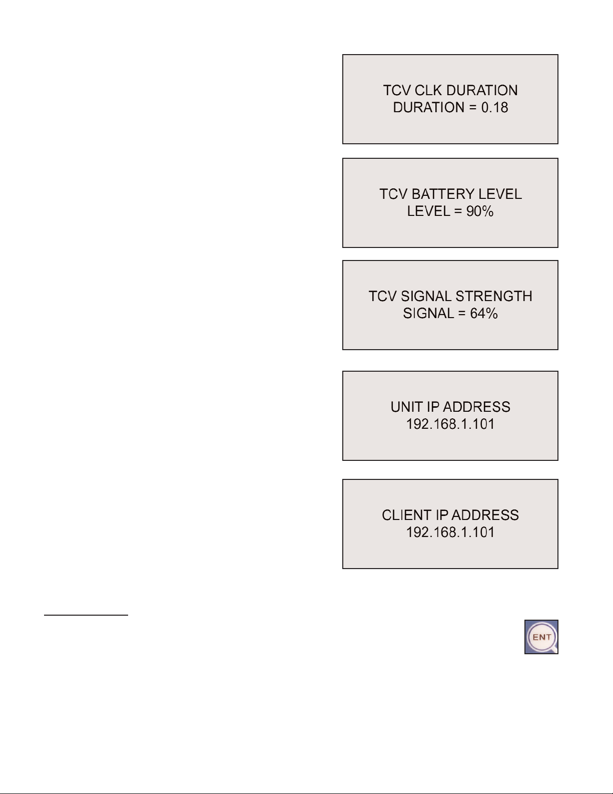
The third screen shows the click duration (cycle time)
for the switch wrench in the most recent cycle of the
tool.
The fourth screen displays the current approximate
battery charge for the battery in the wrench. This is an
approximate percentage, not a voltage.
The fifth screen displays a relative signal strength for
the radio signal coming from the switch wrench.
The sixth operating screen displays the current IP
address programmed into the TCV-Ethernet interface.
The seventh operating screen displays the Client IP
Address of the computer that is communicating with
this unit.
Programming
To exit the operating functions display and enter the programming mode, press the Enter
Key.

Page 11
A password is required to enter the programming func-
tions fo the unit. The “Enter Password” window will be
displayed once the Enter button has been pressed.
The default password is “0104”.
The key conventions when entering the password are:
• The left and right arrow buttons move the cursor and currently active digit selection among
the positions.
• The up and down arrow buttons raise and lower the value of the digit that the cursor is
highlighting.
• The Escape button will stop the process of accessing the programming menu and return to
the operating screens.
• The Enter button causes the unit to compare the current password selection to the pass-
word in memory. If the correct password has been selected, access to the programming
menu is granted.
Once the password is accepted, the first item on the program menu is displayed. There are 13
program items for the TCV functions and 15 program items for the Ethernet and miscellaneous
functions. Each item has an entry screen and at least one screen for programming the item.
The program menu navigation conventions are:
• The Up and Down buttons scroll through the menu items in sequence.
• The Enter button opens the current item and presents the screens for editing.
• The Escape button exits an item without changing or saving the value.
• After the item is edited, the Enter button saves and exits. There is often a window that dis-
plays while the new value is being saved. A second press of Enter is used to finish.
The front panel programmable items for TCV functions are:
TCV Batch Count TCV/RST Total/Batch
TCV Timer Min TCV Channel
TCV Timer Max TCV Add Wrench
Count Direction TCV Erase Wrench
Time Between Batches TCV View Wrench ID
Time Between Cycles Relay Settings
TCV Beep Setting
The front panel programming items for Ethernet and miscellaneous functions are:
Local IP Address LCD Contrast
Gateway Address Change Password
Page 12
Subnet Mask Control Cell ID
Port Number Control Channel
Message Timeout Control Name
Resend Attempts Serial Printer
Keep Alive Timeout Bar Code Reader
Time and Date
The serial printer and bar code reader functions are optional. These devices are not supplied
when the system is purchased and must be purchased separately if desired.
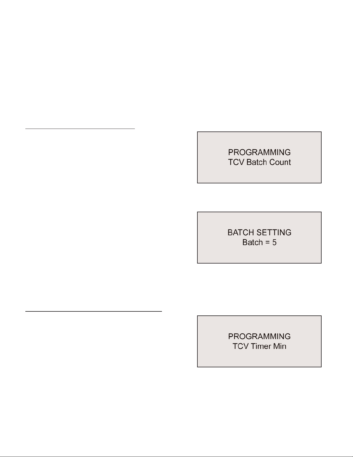
Programming the TCV Batch Count
This model of the TCV is capable of performing batch
counts for batches of from 1 - 99 fasteners. The batch
count controls when the batch relay closes. Batch
count data is also available to the plant floor control
system through the Ethernet communications.
To select the batch count, press the Enter button when
the TCV BATCH COUNT window is displayed.
The the display will show the current batch count. The
Up and Down arrow buttons will increment or decre-
ment the value by one fastener each time the button is
pressed. To change the count more rapidly, the Left
and Right arrow buttons will increment or decrement
the batch count by 10 fasteners.
To exit this program item without changing the value, press the Escape button at any time dur-
ing the process. To save a changed value and make it the active value, press the Enter button
after the value has been changed.
Programming the TCV Timer Min (Minimum)
Two timers control the time limits for an acceptable
switch wrench cycle (time in the “clicked” position).
The TCV Timer Min controls the minimum time specifi-
cation limit. TCV Timer Max controls the maximum
time specification limit for an acceptable cycle.
To program the TCV Timer Min specification, press
the Enter button when the TCV Timer Min window is displayed. The Timer Min window will
open. This window will show the current minimum value of the speicifation.
To exit this program menu item at any time, press the Escape button.

Page 13
To change the specification use the Up and Down but-
tons. Press the Up button to increase the time in 0.01
second increments. Press the Down button to
decrease the time in 0.01 second decrements. The
Left and Right buttons will change the time up and
down by 0.10 second increments and decrements.
The timer can be set for any time between 0.00 and 2.55 seconds, but the TCV Timer Min
specification value must be less than the TCV Timer Max specification value.
Press the Enter button to save the new specification value and return to the main programming
menu.
TCV Timer Max (Maximum)
TCV Timer Max controls the maximum time specification limit for an acceptable cycle. Two
timers control the time limits for an acceptable switch wrench cycle (time in the “clicked” posi-
tion). The TCV Timer Min controls the minimum time
specification limit.
To program the TCV Timer Max specification, press
the Enter button when the TCV Timer Max window is
displayed. The Timer Max window will open. This win-
dow will show the current minimum value of the spe-
icifation.
To exit this program menu item at any time, press the
Escape button.
To change the specification use the Up and Down but-
tons. Press the Up button to increase the time in 0.01
second increments. Press the Down button to
decrease the time in 0.01 second decrements. The Left and Right buttons will change the time
up and down by 0.10 second increments and decrements.
The timer can be set for any time between 0.00 and 2.55 seconds, but the TCV Timer Max
specification value must be greater than the TCV Timer Min specification value.
Press the Enter button to save the new specification value and return to the main programming
menu.
Page 14
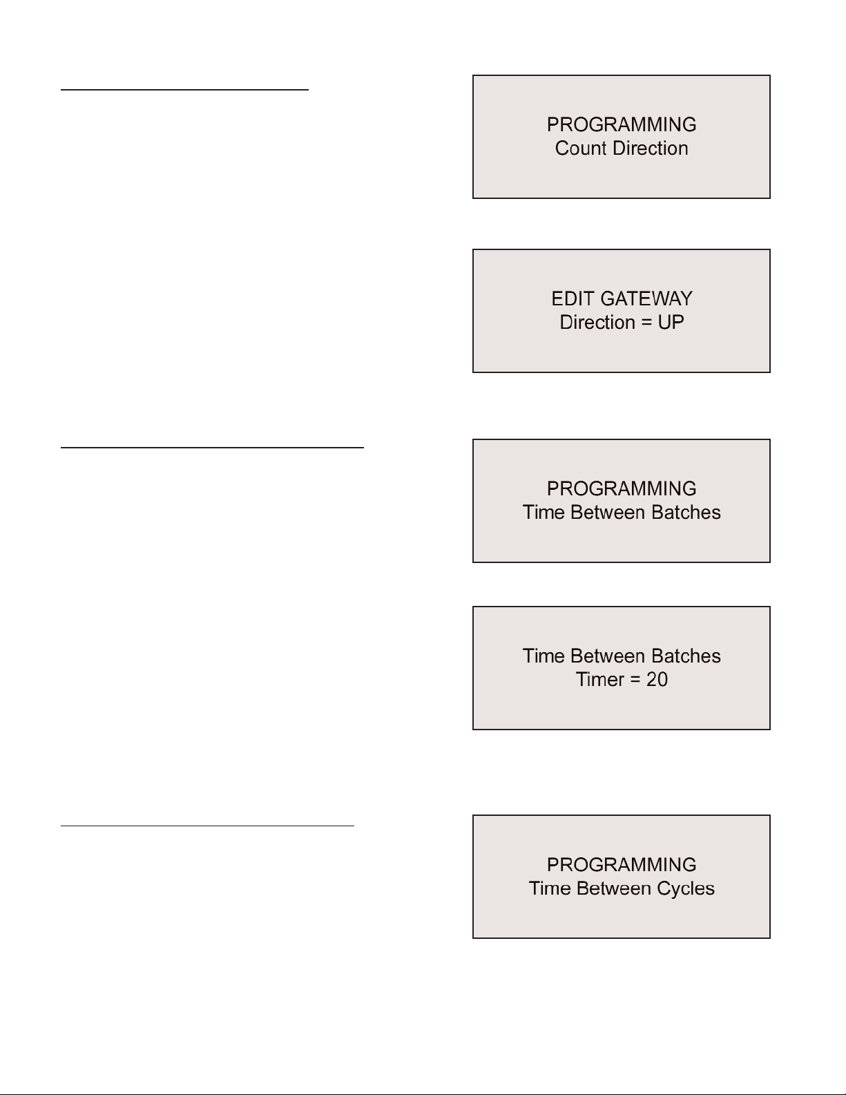
Programming the Count Direction
The unit can be programmed to count acceptable
cycles in a batch in either the upwards (from 0 to total
number in batch) or downwards (total number in batch
to 0) direction.
The Count Direction menu item is selectable for
change by pressing the Enter button when the Count Direction window is active.
When this menu item is entered a new window will be
displayed showing the currrent direction. To change
the direction press any of the arrow buttons (Up,
Down, Left, Right) and then press the Enter button to
set the change and exit.
To exit without change, press the Escape button.
Programming the Time Between Batches
A timer controls the minimum acceptable elapsed time
between batches. This specification is settable
through the Time Between Batches menu item.
To change the time, press the Enter button when the
Time Between Batches item is active. This will open
the item for review or alteration.
The current value for the specification will be dis-
played when the item is open. The Up and Down but-
tons increase or decrease the setting value by one
second. The Left and Right buttons increase and
decrease the setting by 100 seconds with each press
of the button. When the desired value is displayed,
press the Enter button to set the value and return to
the programming menu. To exit this item without changing the value, press the Escape button.
Programming the Time Between Cycles
A timer controls the minimum acceptable elapsed time
between switch wrench cycles (individual fasteners).
This specification is settable through the Time
Between Cycles menu item.
To change the time, press the Enter button when the
Time Between Cycles item is active. This will open the item for review or alteration.

Page 15
The current value for the specification will be displayed
when the item is open. The Up and Down buttons
increase or decrease the setting value by one second.
The Left and Right buttons increase and decrease the
setting by 100 seconds with each press of the button.
When the desired value is displayed, press the Enter
button to set the value and return to the programming
menu. To exit this item without changing the value, press the Escape button.
Programming the TCV Beep Setting
The Beeper in the TCV can be programmed to activate under varying conditions. The available
options are:
• Off (Never)
• Accept (cycle) and Reject (cycle)
• Batch (completion) and Reject (cycle)
• Reject only
The Beep Setting may be accessed when the item is
active in the main programming menu by pressing the
Enter button.
The current beeper setting will be displayed. Press
any arrow button (UP, Down, Left, Right) to scroll
through the available options. When the desired set-
ting is displayed, press the Enter button to activate
that setting and exit this item. This item may be exited without change by pressing the Escape
button.
Programming - Resetting the Total and Batch Counts
The Batch Count and the Total (cycle) Count can both
be reset. To reset either or both counts, press the
Enter button to access this function.
The display will show the two counts, both on the sec-
ond line of the new display. To reset the Total Count,
press the Up button. To reset the Batch Count press
the down button. Press the Enter button to active your
selection and return to the main program selections.
Press the Escape button to exit without resetting.

Page 16
Programming the TCV Channel (RF)
The radios used by the TCV-Ethernet and FM Switch
Wrench use the Zigbee Network Protocol. This allows
the use of many TCV-Ethernet units and FM Switch
Wrenches in close proximity without having to use
separate channels. Because an occasion may arise
where the user wishes to specify a channel, this ability
is provided.
To select a specific channel, press the Enter button
when the TCV Channel item is displayed.
The display will then show the current channel. Use
the Up and Down buttons to specify the desired chan-
nel. To save and activate this setting in the unit, press
the Enter button. To leave this menu item without change, press the Escape button.
If a new channel has been selected and activated, the wrench must be reproagrammed
(learned) into the unit.
Programming - Adding a Wrench (Transmitter)
The TCV-Ethernet and FM Switch Wrench work as a
system. To work together, the wrench must have a
transceiver on it and the transceiver for that particular
wrench must be “learned” (identified and recorded) by
the unit.
It is simplest to perform this function by using the key switch on the side of the unit and the pro-
cedure described later in this manual. If the key is unavailable this function can be performed
through programming.
First, clear the memory on the wrench to be “learned”
by putting it in the “clicked” position and holding it in
that position for ten (10) seconds or until the LED on
the wrench alternates between red and green.
To have the TCV-Ethernet “learn” the new wrench or one with a new transceiver, press the
Enter button when the TCV Add Wrench item is active. The display will then offer the option of
adding the wrench to the limited set of those it recognizes or not.
Press the Enter button to add the wrench and set it as the tool to communicate with or press
the Escape button to exit this program item without changing the wrench to be worked with.
Page 17
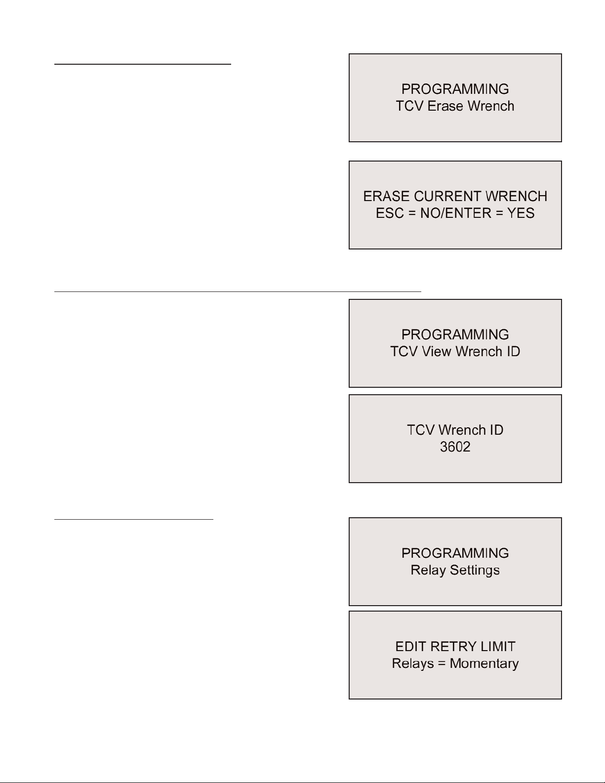
Programming - Erasing a Wrench
The current wrench (transceiver) can be removed
from memory through this function. To access this
function, press the Enter button when the TCV Erase
item is displayed.
The display will change, providing a choice of erasing
the identification number from memory or leaving the
current wrench transceiver active. To erase the
wrench transceiver from memory and return to the
main item sequence, press the Enter button. To exit
this function without erasing the wrench from memory,
press the Escape button.
Programming - Viewing A Wrench (Transceiver) Identification Number
Each wrench transceiver has a unique four-digit identi-
fication number. This allows the unit to work with a
specific tool when multiple tools are used in close
proximity and on the same channel.
The transceiver identification number can be viewed
through this function in the programming menu. Press
the Enter button when this menu item is active to view
the number.
The current identification number will be displayed.
Press any front panel programming button to return to
the main programming menu.
Programming - Relay Settings
The three relay contacts available on the side of the
unit can be programmed to close momentarily or to
remain closed (maintained) until another relay even
occurs. When set to momentary the contacts are
closed for 200ms.
To check or change the relay contact setting, press the
Enter button when this item is active. The display will
then show the current setting. To keep the current set-
ting, press the Escape button. To change the setting,
press any arrow button once, then press the Enter but-
ton to save the change and return to the main menu.
Page 18
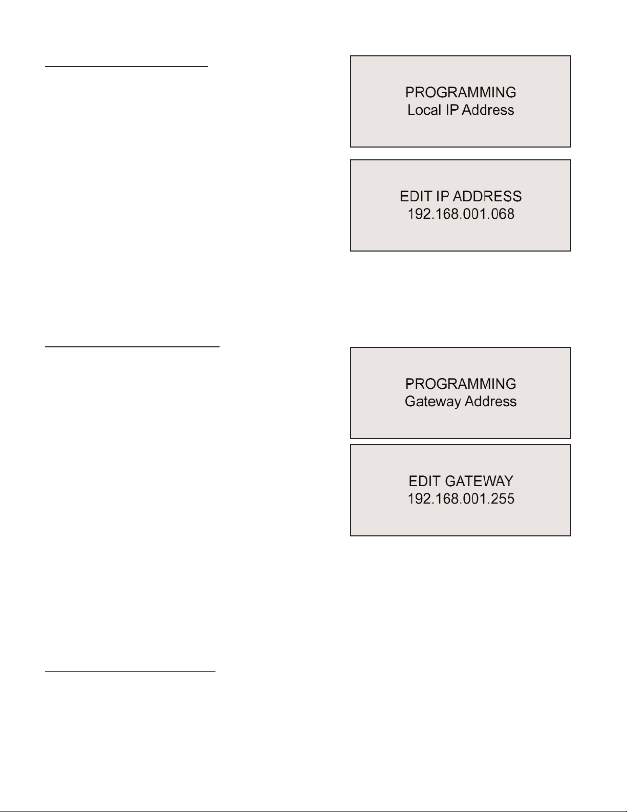
Programming Unit IP Address
The TCV-Ethernet acts as a server. For a server client
(remote computer) to communicate with the unit, the
client must have the internet protocol (IP) address of
the unit.
To set the local IP address for the unit, press the Enter
button when this menu item is displayed.
The current IP address will then be displayed, with one
digit underlined. To move among the address digits,
press the Left or Right buttons. To modify the under-
lined digit, use the Up or Down buttons.
To save the address after the required digits have been changed to reflect the correct address
on the network, press the Enter button. To exit this function at any time without changing the
address, press the Escape button.
Programming Gateway Address
Gateways can act as bridges between separate net-
works. For two devices to communicate between two
separate networks the messages must pass through
each respective network’s gateway.
If the two devices that are communicating are on the
same network, the gateway will not be used and the
address will not matter.
To edit the Gateway Address, press the Enter button
when the function is displayed.
The current Gateway Address will then be displayed,
with one digit underlined. To move among the address digits, press the Left or Right buttons. To
modify the underlined digit, use the Up or Down buttons.
To save the address after the required digits have been changed to reflect the correct Gateway
Address, press the Enter button. To exit this function at any time without changing the address,
press the Escape button.
Programming the Subnet Mask
The Subnet Mask allows the system to determine which IP addresses are local and which IP
addresses are remote.
This manual suits for next models
1
Table of contents
Other Sturtevant Richmont Control System manuals


