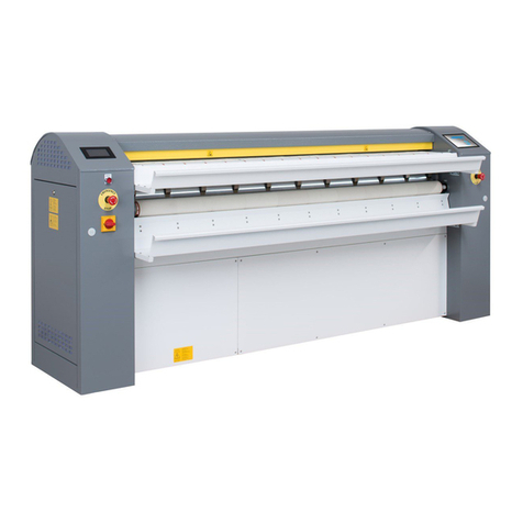
Imesa ECC User manual

K2950SCHEDESS_01 –K2950SCHEDESS_02 (E141203X)
25/08/2015
1
HOW TO REPLACE
A “ECC” CONTROL BOARD WITH
A “IM7” CONTROL BOARD
TUMBLE DRYER “E” SERIES
MOD. 10/14/18/23/34 Kg
FROM MARCH 2002 SERIAL NUMBER E200912064
IMESA S.p.A.
Via degli Olmi 22
31040 Cessalto (TV), Italia
tel. +39.0421.468011
fax +39.0421.468000
www.imesa.it

K2950SCHEDESS_01 –K2950SCHEDESS_02 (E141203X)
25/08/2015
2
INDEX:
1. MANUAL CONTENTS...........................2
2. SAFETY RULES....................................2
3. MANUFACTURER LIABILITY...............3
4. NECESSARY TOOLS............................3
5. COMPOSITION OF THE KIT.................4
6. 2950SCHEDESS_01 INSTALLATION
OF ELECTRONICS PART............................4
7. INSTALLATION OF THE KIT
K2950SCHEDESS_01 –ECC/IM7 CABLING
(6141102X)...................................................7
8. INSTALLATION OF THE KIT
K2950SCHEDESS_01 –CONTACTORS
CONNECTION..............................................9
9. KEYPAD AND DISPLAY
INSTALLATION..........................................10
10. INSTALLATION OF THE
K2950SCHEDESS_02 KIT –COIN
OPERATED DRYERS................................12
11. ELECTRIC DIAGRAMS -
CONVERSION CABLING ECC/IM7
6141102X....................................................14
12. ELECTRIC DIAGRAM OF IM7
CONTROLLED DRYERS...........................15
1. MANUAL CONTENTS
The received kit can be installed in tumble
dryers “E” series, capacity: 10/14/18/23/34
Kg.
This instructions are valid for machines
produced starting from March 2002 until the
serial number E200912064 (December
2009), which were originally equipped with an
ECC –ENTITY control board.
This kit is necessary to update the dryer with
the latest IM7 microprocessor, which has
replaced the old electronic timer since
January 2010.
This document complies with the European
Community Directives in force.
The here written information are addressed to
the technician, who must be sure to fully
understand them before to service the
machine.
These instructions must always be available
for consultation. In case of lost or damage,
please ask to the manufacture for a new
copy.
The manufacturer is not responsible for
consequences arising from the improper use
of the new device installed due to missing or
incomplete reading of this manual.
The manufacturer reserves the right to
change the specifications mentioned in this
manual or the characteristics of each
machine.
Some illustrations in this manual may be
partially different from those assembled on
the machines. Diagram and technical data
may be modified without any previous notice.
The manual, its attachment and this
instruction are part themselves of the
machine, they must be stored near the
machine and follow the machine in case of
sale to another user or technician.
2. SAFETY RULES
Ignoring the following safety rules can cause
damages to people, things and animals.
The installation and maintenance of the here
described component must be performed by
authorized personnel who knows the product

K2950SCHEDESS_01 –K2950SCHEDESS_02 (E141203X)
25/08/2015
3
and in compliance with European standards
on the installation and repair of industrial
machines.
The here describe tumble dryer must be used
for a professional drying of garment and
linen.
Any other use is forbidden if not previously
authorized in written by the manufacturer.
Do not introduce into the machine items other
than the one to be dried. Linen to be dried
must not have been in contact with
hazardous material such as explosives,
detonating and inflammable. In this case the
linen must be rinsed, aired or partially dried.
It is forbidden to dry linen soaked with
substances manifestly dangerous for the
operator health, such as poison or
carcinogenic products.
Do not approach the machine with
combustible or flammable material in order to
avoid the risk of fires and explosions.
Always stick to the drying instructions on the
linen.
The use of the machine is forbidden for
people under 14 years age.
Additional external connection to the
machine, if not duly performed, release the
manufacturer from any responsibility.
These instructions do not cover all
possible risks. User must always pay
high attention and respect carefully the
rules.
3. MANUFACTURER LIABILITY
The instructions written in this manual are not
replacing, but completing the duties deriving
from the safety and accident prevention laws.
With reference to what is written in this
manual, the manufacture is not responsible
for:
Use of the machine not in compliance
with the EU law in matter of safety
and accident prevention.
Wrong machine installation.
Missing of the ordinary and scheduled
maintenance.
Disregarded or not correct application
of the instruction written in the
manual.
difetti di tensione e di alimentazione
di rete.
Not authorized modifications to the
machine.
Machine used by not authorized
personnel.
Not correct installation of the kit.
4. NECESSARY TOOLS
The below listed tools, necessary to install
this kit, are not supplied with this kit, as they
are part of a standard technician kit.
Cordless screw gun;
Cross headed insert;
TORX T30 and T40 screwdriver or insert
for screw gun;
Key No. 8 and No. 10;
Drill insert 5,5 mm diameter;
Stepladder.

K2950SCHEDESS_01 –K2950SCHEDESS_02 (E141203X)
25/08/2015
4
5. COMPOSITION OF THE KIT
The here described kit is available in two
versions:
- Standard with extension “_01”;
- Coin-op with extension “_02”.
- K2950SCHEDESS_01 (standard)
ITEM
DESCRIPTION
Q.TY
6111105B
ES 10/34 IM7 box wiring
1
4141103X
ECC>IM7 Keypad std
1
2141141
ECC>IM7 Keypad support
1
2950DISESIM7
IM7 Display board
1
2950DISTA015
Rounded spacer
Nylon F/F L=15mm
4
4936RGZ10X30
Washer Fe 10x30x2.5
ZINB
4
4936DAF003M
Self-Locking Nut
DIN 982 M3 ZINB
4
6141102X
Wiring to convert
ECC –IM7
1
2950SENSOPT1
Temperature Probe
PT1000 Class B
1
6110807X
Flat Cable IM7>Display
10-20 PIN ES 10/34
1
1936FERCAVNY
Cable Fastener in Nylon
Richco
3
4936VITBO516
Screw TBEI INOX M5X16
4
4936RPZ0005M
Washer Fe 5 ZINB
4
4936DAFA005M
Self-Locking Nut
Din 982 M5 Zinb
4
2950CONMA02V
Two ways male connector
Mate-N-Lock
1
2950GU643TER
Shrinkt Tubing D.6,4/4,2
NE
50 cm
4936FASSN14B
Clamps NB 14B
1
2950FASCV140
Cable Tye 140x2.5 Cod.
CV –140S
10
2950GVS15018
Silicon tube
140x2.5cod.CV-14S
10 cm
2950MORSP025
Borne Mammuth 2 ways
2
4936VAN3913Z
Self-Treating Screw
ZN 3,9x13 UNI 7981
3
E100301X_ENG
IM 7 User notice
1
E141203X
These instructions
1
- K2950SCHEDESS_02 (Coin Op)
ITEM
DESCRIPTION
Q.TY
6111105B
ES 10/34 IM7 box wiring
1
4141102X
ECC>IM7 Keypad Coin
1
2141141
ECC>IM7 Keypad support
1
2950DISESIM7
IM7 Display board
1
2950DISTA015
Rounded spacer
Nylon F/F L=15mm
4
4936RGZ10X30
Washer Fe 10x30x2.5
4
ZINB
4936DAF003M
Self-Locking Nut
DIN 982 M3 ZINB
4
6141102X
Wiring to convert
ECC –IM7
1
2950SENSOPT1
Temperature Probe
PT1000 Class B
1
6110807X
Flat Cable IM7>Display
10-20 PIN ES 10/34
1
1936FERCAVNY
Cable Fastener in Nylon
Richco
3
4936VITBO516
Screw TBEI INOX M5X16
4
4936RPZ0005M
Washer Fe 5 ZINB
4
4936DAFA005M
Self-Locking Nut
Din 982 M5 Zinb
4
2950CONMA02V
Two ways male connector
Mate-N-Lock
1
2950GU643TER
Shrinkt Tubing D.6,4/4,2
NE
50 cm
4936FASSN14B
Clamps NB 14B
1
2950FASCV140
Cable Tye 140x2.5 Cod.
CV –140S
10
2950GVS15018
Silicon tube
140x2.5cod.CV-14S
10 cm
2950MORSP025
Borne Mammuth 2 ways
2
4936VAN3913Z
Self-Treating Screw
ZN 3,9x13 UNI 7981
3
6111123X
Additional Cabling IM7 for
Coin box
1
E100301X_ENG
IM 7 User notice
1
E141203X
These instructions
1
6. 2950SCHEDESS_01 INSTALLATION
OF ELECTRONICS PART
Before to service the machine, it must be
completely switch off and the temperature
must be the room temperature. Suppling
cable must be disconnected from the plug
and from the electric board. Compressed
air and gas supply, if provided, must also
be disconnected.
a) Open the above frontal cover, open the
filter door, remove the above cover (if
present), remove the back panels;
b) The ECC board is placed inside the
programmer box, together with the display
and the keypad.

K2950SCHEDESS_01 –K2950SCHEDESS_02 (E141203X)
25/08/2015
5
Before to remove the ECC box, label the
male connectors (the ones with the cables)
as shown below:
ATTENZIONE
JP9 and JP11 are both 12 ways
connectors. To distinguish between one
and the other connector, check where the
door sensor back cable is addressed. The
door sensor is contained only in the JP11
connector. To check the detailed list of the
connectors, see last paragraph of this
instructions.
c) Remove the programmer box from the
above room. It is fixed by three self-drilling
cross headed screws: two at the base, on
the above bracket.

K2950SCHEDESS_01 –K2950SCHEDESS_02 (E141203X)
25/08/2015
6
d) Remove the wiring plastic ring support
(new supports are supplied with the kit).
Remove the plastic cable ties, if present,
and remove the wiring. Place the wiring,
correctly divided, on the above shelf.
e) Using the suitable opening on the IM 7
box, bring the display double flat to the
CN14 and CN12 connector and install it.
f) Label the CO connectors on the IM7 board
box as shown in the below pictures:
g) Place the IM 7 box on the above shelf, on
the right side, 10 cm distant from the front
profile.

K2950SCHEDESS_01 –K2950SCHEDESS_02 (E141203X)
25/08/2015
7
h) Use the plastic ring support to maintain
order in the original wiring. To fix the new
plastic ring to the shelf, hole the shelf using
a 4mm drill. The new wiring hold will keep
also the new wiring.
i) Fast the IM7 control board using the
supplied self-drilling screw. Be sure the
box is grounded by means of the
connector eyelet.
7. INSTALLATION OF THE KIT
K2950SCHEDESS_01 –ECC/IM7
CABLING (6141102X)
The wiring supplied with the kit is completed
with some interconnections to adapt the old
machine connection to the new IM 7 control.
The wiring code 6141102X was supplied
complete of labelled connectors and
numbered cables. Each connector and cable
can be easily recognized if compared with the
electric diagram reported at the end of these
instructions.
a) Connect the JP female connectors of the
new wiring to the JP male connects of the
old wiring.

K2950SCHEDESS_01 –K2950SCHEDESS_02 (E141203X)
25/08/2015
8
b) Connect the “CO” male connectors to the
correspondent “CO” female connectors of
the IM 7 board box. The 2 poles connector
near CO12 will not be used; it must be
closed with the supplied white empty
connector.
c) Pass the wiring coming out for the CO9
connector through the back box holes.

K2950SCHEDESS_01 –K2950SCHEDESS_02 (E141203X)
25/08/2015
9
d) See the contactor connection instructions
given at the paragraph 8.
e) Remove the original probe saving the
cable: only the last 15 cm of the cable
must be cut. Save the probe bulb and the
elastic washers needed to fix the new
probe to the dedicated bracket.
f) Join the new probe using the supplied two
ways borne. The cable colours have no
effect. Protect the borne with the red glass-
silicone sheath, to avoid the contacts
oxidation.
g) Fix the new probe in the previous position
using the elastic washers and recover the
exceeding cable.
8. INSTALLATION OF THE KIT
K2950SCHEDESS_01 –CONTACTORS
CONNECTION
a) Pass the cables through the dedicated
place behind the electric board. Enter
inside the electric board using the heating
wiring opening.
b) Label the contactors and the thermal
protections devices as shown by the next
picture:

K2950SCHEDESS_01 –K2950SCHEDESS_02 (E141203X)
25/08/2015
10
LABEL
FUNCTIONS
VE
Ventilation
RMVE
Fan thermal protections
SX(*)
Left drum rotation
DX(*)
Right drum rotation
RMMO (*)
Drum thermal protections
(*) only in case of reversing drum
c) Insulate the cable which bring the 230V
common to the 95 NC contact of the
RMVE thermal device. In case the
machine is reversing drum equipped, open
the series with the 95NC second contact of
the RMMO thermal device.
ATTENTION
Original cable must only be insulated,
they must not be cut from the original
wiring. They should stay into the electric
board even if not used.
To insulate the cable use a shrink tubing
and a lighter.
d) The cables coming from the connector
CO9 must be wired as per the bellow table:
Cable No.
Coming from
Going to
53
CO9 –Pos 3
95NC - RMVE
54
CO9 –Pos 4
21NC –SX
55
CO9 –Pos 5
22NC –DX
56
CO9 –Pos 6
97NO –RMVE
57
CO9 –Pos 7
97NO –RMMO
58
CO9 –Pos 8
98NO –RMMO
59
CO9 –Pos 9
98NO –RMVE
e) The kit is comprehensive of single
connectors to be used to interconnect the
contactors and the main terminals:
Cable No.
Coming from
Going to
61
A2 –VE
96NO –RMVE
62
A2 –SX
21NC –DX
63
A1 –DX
22NC –SX
0C
N (blue main
inlet terminal)
95NC - RMMO
0D
A2 –DX
A1 –SX*
0D
A1 –SX *
96NC - RMMO
ATTENTION
If the machine is not reversing drum
equipped, the contactors SX and DX and
the thermal contactor RMMO are not
present. Therefore the cables referring to
the contactors SX, DX and RMMO must be
insulated, as not used.
Please go back to paragraph 7 to fit the new
temperature probe.
9. KEYPAD AND DISPLAY
INSTALLATION
a) Stick the keypad (code: 4141103X) on
the dedicated squared iron support (code:
2141141X). The flat cable must be
passed through the dedicated hole,
paying attention not to arm it.

K2950SCHEDESS_01 –K2950SCHEDESS_02 (E141203X)
25/08/2015
11
b) Insert the 4 white spacers, 15 mm high
(code: 2950DISTA015) on the 4 pinion on
the support back. Install the display and
closet he washers and the nut M3
(supplied). Connect the flat to the keypad.
c) Place the keypad in the middle of the
cover opening. Using a marking pen,
mark the 4 holes position on the cover
inner side.
d) Use a 5,5 mm drill to hole the panel and
fix the display using the supplied TORX
M5 screws.

K2950SCHEDESS_01 –K2950SCHEDESS_02 (E141203X)
25/08/2015
12
e) Connect the double sheathed flat to the
connectors on beck of the display board.
10. INSTALLATION OF THE
K2950SCHEDESS_02 KIT –COIN
OPERATED DRYERS
Install the CO6 connector only on coin
operated dryers. On the contrary, do not
install this connector, as the cable 3 and 0F
conducts 230V tension. These two cables are
used to supply the coin mechanism coil or the
electronic coin mechanism board. These two
cables must not be used for other purposes.
The coin mechanism wiring is composed by
two parts, one wiring inside the IM7 board
box (code: 6111123X, 6 poles green
connector), the other wiring is developed
outside the IM7 box and it reachs the
payment systems.
First of all, install the wiring identified by the
code 611123X inside the IM7 box, connecting
the green connector to the slot called CN19.
Pass the CO6 white female connector
through the dedicated hole (above CO5). The
cable nr 3 and nr 0 of the inside wiring must
be connected as show in the next table. The
cable nr 0 must be connected to the terminal
nr 2 of the connector CO9. The cable nr 3
must be connected to the terminal nr 3 of the
CO12.
Connect the sheathed wiring to the CO6
connector and reach the coin mechanism
installed on the machine.
The wiring of the connector CO6 must follow
the below chart:
Wire Nr
Coming from
Going to
" 3
CO6 –Pos 1
230V (max 0,5 A)
0F
CO6 –Pos 2
Neutral
43
CO6 –Pos 3
Common Coin 1
44
CO6 –Pos 4
Back Coin 1
45
CO6 –Pos 5
Common Coin 2
46
CO6 –Pos 6
Back Coin 2
Below the diagram.
Please note the “G1” and “G2” are two
different entrances dedicated to two different
payment systems. The entrance can be
programmed using the coin menu from the
control board. In the programming menu, the
entrances are called COIN 1 and COIN 2.

K2950SCHEDESS_01 –K2950SCHEDESS_02 (E141203X)
25/08/2015

K2950SCHEDESS_01 –K2950SCHEDESS_02 (E141203X)
25/08/2015
11. ELECTRIC DIAGRAMS - CONVERSION CABLING ECC/IM7 6141102X

K2950SCHEDESS_01 –K2950SCHEDESS_02 (E141203X)
25/08/2015
12. ELECTRIC DIAGRAM OF IM7 CONTROLLED DRYERS

K2950SCHEDESS_01 –K2950SCHEDESS_02 (E141203X)
25/08/2015
This manual suits for next models
1
Table of contents
Other Imesa Control System manuals
Popular Control System manuals by other brands

Alpha Communications
Alpha Communications TekTone Tek-CARE NC110A Operation, installation and service manual

Airzone
Airzone RADIANT365 installation manual

Philips
Philips Lytemode 6-Button Remote Station user guide

PendoTECH
PendoTECH NFF Technical notes

Tume
Tume AgroCont manual
AVer
AVer SVC Quick installation guide

DEFA
DEFA Home user manual

Highway Care
Highway Care BarrierGuard 800 Product and installation manual

CURB
CURB CURB Installation & user guide
Keystone RV
Keystone RV SolarFlex 600i-L quick start guide

Alcorn Mcbride
Alcorn Mcbride DMX OverRide user guide

HandyTrac
HandyTrac Touch Installation & operation guide
