Sturtevant Richmont TCVe2 User manual

Torque Control Verifier Ethernet 2
2.4GHz FM TCVe2 User Manual
Part Number 857414 Rev A
01 July 2020

TCV e2 User Manual 2 of 36 P/N 857414 Rev A
07/01/2020
Table of Contents
Quick Start Guide..........................................................................................................................................4
Overview.......................................................................................................................................................5
Warnings...................................................................................................................................................5
Cautions ....................................................................................................................................................5
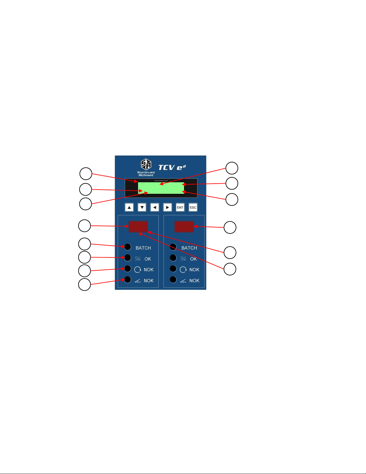
Unit Overview ...........................................................................................................................................5
Compatible Tools ......................................................................................................................................5
Using The Unit...............................................................................................................................................6
Concepts ...................................................................................................................................................6
Run Screen ................................................................................................................................................6
Configuring The Unit.....................................................................................................................................8
Tool Info Group.........................................................................................................................................8
Common Fields .....................................................................................................................................8
TAC Fields..............................................................................................................................................9
Click Tool Fields...................................................................................................................................10
Status Info Group....................................................................................................................................12
Network Connection Info Group.............................................................................................................12
IP Info Group...........................................................................................................................................12
Open Protocol.............................................................................................................................................14
ToolsNet......................................................................................................................................................16
PFCS Setup ..................................................................................................................................................18
EtherNet/IP™ ..............................................................................................................................................20
Studio 5000 Add-On Instructions............................................................................................................20
Connection Points...................................................................................................................................20
Output (O->T) Connection Points .......................................................................................................20
Input (T->O) Connection Points ..............................................................................................................21
Input Connection Points for Last Tightening Data..............................................................................21
Input Connection Points for Current Operation Status ......................................................................23
TCVe2 Setup in Studio 5000....................................................................................................................24
Importing the EDS file.........................................................................................................................24
Project Setup.......................................................................................................................................27
Discrete I/O.................................................................................................................................................30

TCV e2 User Manual 3 of 36 P/N 857414 Rev A
07/01/2020
Data Management......................................................................................................................................32
Read/Write..............................................................................................................................................32
Barcode Reader.......................................................................................................................................32
Firmware Updates.......................................................................................................................................35
Product Specification..................................................................................................................................36

TCV e2 User Manual 4 of 36 P/N 857414 Rev A
07/01/2020
Quick Start Guide
This quick start will guide you through the process of configuring the unit for first time use. Plug the
provided power cable into the unit and 100-240 VAC power and turn on the power switch. The LEDs
illuminate and the beeper sounds a series of quick beeps. “TVC E2” and the firmware version number
are displayed when the unit boots up.
To use a tool with the TCV e2, you must first learn the tool to the TCV e2.
•Press or until the Tool screen is displayed.
•Press or to highlight an open tool slot (ie. “Tool 1 None”). Press ENT.
•Enter Password (0104) by pressing or to change the number. Press to move to the next
position. When all four positions have been set, press ENT to submit the password. An incorrect
password entry will display “Invalid Password”.
•Press ENT.
•“Learn” is displayed on the screen.
•Press or to change which interface to learn the tool in to.
•Click or power on the tool.
•The interface blue BATCH and green Torque/Angle LEDs light. The screen displays the Tool
Number, Tool Type, Radio ID, and Tool Serial Number.
•Press ESC to go back.
To define the parameter settings for the tool:
•Press or to highlight the desired tool. Press ENT.
•Press or until “Edit” is displayed on the screen. Press ENT.
•Press or to cycle through the parameter settings. Press ENT to start modifying the values.
oUse the arrow keys to toggle between values.
oPress or to change numerical values; press or to switch to another digit.
•Press ENT to save the value or ESC to cancel without saving.
•Press ESC twice to back out to the main menu.

TCV e2 User Manual 5 of 36 P/N 857414 Rev A
07/01/2020
Overview
Warnings
!
Do not disassemble the unit for repair or modifications. There is a high electrical voltage inside
the unit that could cause electric shock.
!
Do not allow any type of liquid to come into contact with any part of the unit.
!
Insert all fittings fully into their mating receptacles. Failure to do so could result in injury.
!
Do not fold, bend or apply excessive force to any cable or fitting.
Cautions
Please use caution when handling this or any other electrical appliance.
•This unit accepts an AC input voltage from 100-240 VAC. Trying to operate this unit with a
voltage outside that range may cause damage to the unit.
•Avoid placing or storing this unit in a location where it may become wet or dust covered.
•Do not place or mount this unit in an unstable area.
•Dropping this unit may result in personal injury or damage to the unit.
•Before performing any maintenance on the unit, make sure to turn it off and remove the power
plugs.
•There are no user serviceable parts inside the main enclosure of the unit.
Unit Overview
The TCV e2 is equipped with a main display, two segment displays (one for each interface), navigation
keys, enter and escape buttons. The beeper and LEDs provide an indication for any combination of
accepts, rejects, and batch completions.
The TCV e2 has one RJ-45 Ethernet port for network connectivity.
Two USB-A connectors are provided for firmware updates, results downloads, or connection to barcode
scanners.
The 13-pin I/O connector provides discrete I/O capabilities to define up to 4 inputs and 6 outputs using
the discrete I/O capabilities of the TCV e2.
The power plug accepts 100-240 VAC at 50-60 Hz.
Compatible Tools
The TCV e2 works with the following models of tools:
•SLTC-FM 2.4 GHz preset clicker-type torque wrenches (CLK)
•TAC Torque/Angle Control 2.4 GHz Preset Wireless Click Wrench (TAC)
The TCV e2 can associate with up to 10 Sturtevant Richmont radio torque tools across two interfaces.
To use a tool with the TCV e2, you must first “learn” the tool to the qualifier. The process to do this is
described in the Quick Start section. Tools are activated directly by the unit.

TCV e2 User Manual 6 of 36 P/N 857414 Rev A
07/01/2020
Using The Unit
Concepts
Interfaces - The TCV e2 has 2 interfaces. Interfaces within the TCV e2 work almost like having 2 logical
qualifiers inside the single physical qualifier. Some settings, such as IP Address, are shared between the
interfaces. Each interface has its own tightening log and can be controlled separately by a plant control
system.
Tools - The TCVe2 can associate with up to 10 Sturtevant Richmont radio torque tools. Tools are
assigned to a single interface, which may be changed at any time.
Run Screen
1. Count –The number of tightenings completed in the current batch.
2. Batch –The number of tightenings required for the current batch.
3. Tool Number –The number of the tool used.
4. Tightening Status –The status of the last tightening.
5. Torque Value –Value of the last torque received (for TAC only).
6. Angle Value –Value of the last angle received (for TAC only).
7. Interface 1 Tool Indicator –Displays tool number that is active on Interface 1.
•“- -“ indicates the interface is suspended.
•“00” indicates the interface has no active parameter
8. Interface 2 Tool Indicator –Displays tool number that is active on Interface 2.
•“- -“ indicates the interface is suspended.
•“00” indicates the interface has no active parameter
9. Interface 1 Batch Status –Illuminates blue when complete.
1
T04 OK 109.90
1/3 0°
0.5
04
2
3
4
5
6
9
10
8
12
11
7
14
13

TCV e2 User Manual 7 of 36 P/N 857414 Rev A
07/01/2020
10. Interface 1 Torque/Angle Status OK –Illuminates green when accepted.
11. Interface 1 Torque Status NOK –Illuminates red when rejected.
12. Interface 1 Angle Status NOK –Illuminates red when rejected.
13. Tool Status Indicator –This decimal point indicates the tool has not communicated with the
controller or the radio signal strength is below the recommended minimum level for use.
14. Programming Indicator –This decimal point indicates the controller is trying to program the
tool.
NOTE: Interface 2 status indicators operate in the same manner as the Interface 1 status indicators.
The run screen for an SLTC-FM tool displays
The run screen for a TAC tool can display the following:
Pressing ENT while on the run screen will replace the batch count with the click torque value.
Pressing ESC will return to the previous format.
T04 OK
1/3
•Tool Number
•Tightening Status
•
Batch Count
•Tool Number
•Tightening Status
•Peak Torque
•Batch Count/Click Torque
•Angle
T04 OK P 109.90
C 105.6 0°
T04 OK 109.90
1/3 0°

TCV e2 User Manual 8 of 36 P/N 857414 Rev A
07/01/2020
Configuring The Unit
The top level screens are:
•Tool Info Group
•Status Info Group
•Network Connection Info Group
•IP Info Group
Pressing or cycles through the groups.
Pressing or cycles through the items within that group.
Tool Info Group
The Tool Info Group provides all details about the tools learned into the TCV e2. Pressing or cycles
through the 10 Tool screens. Each screen displays:
•Tool #
•Tool Type
•Tool Serial Number
•Radio ID
•Radio Signal Strength
To access the available functions for the displayed tool, press ENT.
Enter the password as described in the Quick Start section.
The functions available for each tool include:
•Select –select the current tool for use.
oPress ENT. With “Select” displayed on the screen, press ENT again to activate the tool.
•Forget –removes the tool from the unit.
oPress ENT.
oPress ENT again to confirm deleting the tool from the unit.
•Edit –edit the current tool parameters.
oPress ENT.
oPress or to cycle through the parameter settings. Press ENT to start modifying the
values.
oUse the arrow keys to toggle between values. Press or to change numerical values;
press or to switch to another digit.
oPress ENT to save the value or ESC to cancel without saving.
oPress ESC twice to back out to the main menu.
Common Fields
Interface
Default: 1
Range: 1 to 2
This field indicates the interface to which the tool is currently assigned.
Each tool can only be assigned to one interface.
Batch
Default: 1
Range: 1 to 255
This setting determines how many good tightenings must be performed in the parameter to complete a
batch.

TCV e2 User Manual 9 of 36 P/N 857414 Rev A
07/01/2020
Lock on batch
Default: no
This setting determines if the unit will lock or restart the parameter when a batch is completed. When
set to yes, the qualifier will stop when a batch is completed and transition to a no active parameter
state. When set to no, the qualifier will restart the parameter when a batch is completed.
TAC Fields
Mode
Default: Peak
Values: Peak, TAM
This setting controls the mode the tool uses to determine the torque.
Autoclear Time
Default: 1
Range: 0.0 to 9.9 seconds
Available Modes: all
This setting controls the amount of time the torque must be steady before it is reported.
Dwell Time
Default: 5.0
Range: 0.0 to 25.5 seconds
Available Modes: all
This setting controls the amount of time permitted for reseating the tool or ratcheting.
Head Length
Default: 36.50 mm
Values: 0 to 100 mm
Available Modes: all
This setting defines the common centerline length of the head used with the tool. If this value is not
entered correctly, torque measurements will be invalid.
Some standard head lengths based on capacity and head type are:
Torque Unit
Default: in.lb
Values: in.lb, ft.lb, N.m, cm.kg, m.kg, cNm
Available Modes: all
This setting controls the units of Min Torque and Max Torque, as well as the torque reported with each
tightening.
Snug Torque
Default: 10% of tool capacity
Range: 0 to Min Trq
Available Modes:TAM
This setting controls the torque threshold at which the tool starts measuring the angle.
Min Torque
Default: 10% of tool capacity

TCV e2 User Manual 10 of 36 P/N 857414 Rev A
07/01/2020
Range: 0 to tool capacity
Available Modes: all
This setting controls the minimum required torque for a valid tightening. This value must be less than
Max Torque.
Target Torque
Default: 10% of tool capacity
Range: Min Trq to Max Trq
Available Modes: all
This setting controls the target torque for the tool.
Max Torque
Default: 99% of tool capacity
Range: 0 to tool capacity
Available Modes: all
This setting controls the maximum allowed torque for a valid tightening. This value must be greater than
Min Torque.
Min Angle
Default: 0
Range: 0 to 9999
Available Modes: TAM
This setting controls the minimum required angle for a valid tightening. This value must be less than Max
Ang.
Max Angle
Default: 0
Range: 0 to 9999
Available Modes: TAM
This setting controls the maximum allowed angle for a valid tightening. This value must be greater than
Min Ang.
Click Tool Fields
Timer Min
Default: 0
Range: 0 to 2.55 seconds
This setting controls the minimum amount of time the tool must be held in the clicked position for a
valid tightening. This value must be less than Timer Max.
Timer Max
Default: 1.00 seconds
Range: 0 to 2.55 seconds
This setting controls the maximum amount of time the tool may be held in the clicked position for a
valid tightening. This value must be greater than Timer Min.
TBC (Time between cycles)
Default: 0
Range: 0 to 9999 seconds

TCV e2 User Manual 11 of 36 P/N 857414 Rev A
07/01/2020
This setting controls the minimum amount of time after an accepted tightening before another
tightening should be accepted. Any additional tightenings performed within this time after an accepted
tightening will be automatically considered a reject.
TBB (Time between batches)
Default: 0
Range: 0 to 9999 seconds
This setting controls the minimum amount of time after a batch completion before another tightening
should be accepted. Any additional tightenings performed within this time after a batch completion will
be automatically considered a reject.
Serial Number
Default: 0000000000
Range: 0000000000 to 9999999999
This setting controls the serial number of the tool. The tool serial number is reported to the network
with tightenings performed by the tool.

TCV e2 User Manual 12 of 36 P/N 857414 Rev A
07/01/2020
Status Info Group
Pressing cycles through these screens:
•VIN 1= –This screen will display the VIN associated to Interface 1.
•VIN 2= –This screen will display the VIN associated to Interface 2.
•Last Tightening –This screen will display the last torque event logged.
Network Connection Info Group
If no connections are active there will only be one sub-screen:
No active connections
IP Info Group
The IP Info Group provides the configuration options for the TCV e2. Pressing or cycles through
these screens:
•Unit IP Address
•Subnet Mask
•Gateway
•MAC Address
•Qualifier Radio Info
Pressing ENT while on the Unit IP Address, Subnet Mask, or Gateway screens will activate the
PROGRAMMING screen which provides additional options. (The MAC address is assigned by the factory
and cannot be changed.) Changes to these settings only apply after the qualifier is restarted. The
settings in this page apply to all interfaces.
IP Address
Default: 192.168.1.67
This setting controls the IP address of the qualifier for Ethernet networks.
Subnet Mask
Default: 255.255.255.0
This setting controls the subnet mask for Ethernet networks.
Gateway
Default: 192.168.1.113
This setting controls the default gateway setting for Ethernet networks.
Edit Password
Default: 0104
The password is 4 numbers.
XBEE Channel
Default: 1
Range: 1 to 12
This setting controls which channel is used by the qualifier radio. All tools learned to the qualifier will be
set to this channel automatically as part of the learn process. In general, this setting does not have to be
changed, but if tool communication is not working reliably, changing this setting may improve
communication.

TCV e2 User Manual 13 of 36 P/N 857414 Rev A
07/01/2020
Reset Defaults
Default: All
Range: All, Configuration, Jobs, Tools, Events,
The Reset Defaults screen allows you to restore the unit to the factory defaults. You may select some or
all parts of the configuration to reset.

TCV e2 User Manual 14 of 36 P/N 857414 Rev A
07/01/2020
Open Protocol
This chapter describes the support for the Open Protocol in the TCV e2. Command MIDs and revisions
referred to in this document are from the Open Protocol Specification Release 1.3 Revision 1. The setup
menu for ACOP is located under the IP Info Group programming menu.
Port Number
Range: 0 to 65535
Default: 04545
This setting controls the network port on which the unit listens for Open Protocol connections to
interface 1. The network port used for interfaces 2 will be the following ports For example, the default
setup listens for interface 1 connections on port 4545 and interface 2 connections on port 4546. If this
setting were changed to 5000, the qualifier would listen for interface 1 connections on port 5000 and
interface 2 connections on port 5001.
Message Timeout
Range: 0 to 3600 seconds
Default: 10 seconds
This setting controls how long the qualifier will wait for a response from the client when sending a
subscription notification packet, such as MID 0015 or MID 0061. If no response is received within the
specified ack timeout, the qualifier will try again, up to the specified number of retries. If no response is
received after all retries, the ACOP connection is considered broken and will have to be re-established.
This will terminate all subscriptions that were established on that connection, regardless of which one
did not receive a response.
Resend Attempts
Range: 0 to 10
Default: 3
This setting controls how many times the qualifier will resend a subscription notification packet, such as
MID 0015 or MID 0061, to the client. If no response is received within the specified ack timeout, the
qualifier will try again, up to the specified number of retries. If no response is received after all retries,
the ACOP connection is considered broken and will have to be reestablished. This will terminate all
subscriptions that were established on that connection, regardless of which one did not receive a
response.
Keep Alive:
Range: 0 to 3600 seconds
Default: 30
This setting controls how long in seconds the unit will keep a connection open without any commands.
This value is recommended to be more than twice the rate at which the client will send keep alive
packets to ensure the connection is not closed due to a single missed keep alive packet. For example, if
the client is configured to send keep alive packets at a 20 second interval, the keep alive setting on the
unit should be more than 40 seconds. The keep alive function can be disabled by setting the keep alive
to 0. When set keep alive is set to 0, the unit will not close an Open Protocol connection due to
inactivity.

TCV e2 User Manual 15 of 36 P/N 857414 Rev A
07/01/2020
OP Cmd Enable
Default: Yes
This setting determines if the unit will respond to “Open Protocol control” commands. These commands
are generally the ones that control unit operation or modify configuration. When this setting is set to
yes, all supported commands listed below are handled. When set to no, the following MID commands
will return an error:
• 0018 Parameter Select
• 0019 Parameter Batch Size
• 0020 Parameter Reset Batch
• 0038 Job Select
• 0039 Job Restart
• 0042 Tool Disable
• 0043 Tool Enable
• 0050 VIN Download
• 0082 Write Time
• 0127 Job Abort
• 0130 Job Off
• 0150 Multi ID Download
• 0156 Reset Latest Identifier
• 0157 Reset All Identifiers
Cell ID
Range: 0 to 9999
Default: 0000
This setting controls the value put in the Cell ID field of Open Protocol commands such as MID 0001 and
0061. The same Cell ID will be used for connections on all interfaces.
Channel ID
Range: 0 to 99
Default: 00
This setting controls the value put in the Channel ID field of Open Protocol commands such as MID 0001
and 0061. The same Channel ID will be used for connections on all interfaces.

TCV e2 User Manual 16 of 36 P/N 857414 Rev A
07/01/2020
ToolsNet
This chapter describes the support for the ToolsNet Open Protocol in the TCV e2. Implementation of the
protocol is according to ToolsNet Open Protocol version 3.5. The TCV e2 reports System Type as 29 and
System Name as “TCV e2”. The setup menu for ToolsNet is located under the IP Info Group
programming menu.
Int 1 Enabled
Default: Disabled
This setting determines if the qualifier will attempt to establish ToolsNet connections for the specified
interface. Unlike the other network protocols supported by the qualifier, ToolsNet requires the
controller to establish connections. Since the qualifier will repeatedly make network requests to attempt
to establish network connections to the ToolsNet server, you should only enable ToolsNet if you have a
server set up in the network and only for the interfaces that are in use.
Int 2 Enabled
Default: Disabled
This setting determines if the qualifier will attempt to establish ToolsNet connections for the specified
interface. Unlike the other network protocols supported by the qualifier, ToolsNet requires the
controller to establish connections. Since the qualifier will repeatedly make network requests to attempt
to establish network connections to the ToolsNet server, you should only enable ToolsNet if you have a
server set up in the network and only for the interfaces that are in use.
PIM Address
Default: 192.168.001.066
This setting controls the IP address the qualifier will use to establish a ToolsNet connection.
PIM Port
Default: 06575
Range: 0 to 65535
This setting controls the port the qualifier will use to establish a ToolsNet connection at the PIM server
address.
PIM Retry Interval
Default: 60
Range: 0 to 3600 seconds
This setting controls how long the qualifier will wait after a failed attempt to establish a ToolsNet
connection before it tries again.
Result Timeout
Default: 5
Range: 0 to 60 seconds
This setting controls how long the qualifier will wait for a response from the ToolsNet server when
sending a tightening or keep alive packet. If no response is received within the specified result timeout,
the qualifier will try again, up to the specified number of retries. If no response is received after all
retries, the ToolsNet connection is considered broken and will have to be reestablished.

TCV e2 User Manual 17 of 36 P/N 857414 Rev A
07/01/2020
Keep Alive
Default: 30
Range: 0 to 3600 seconds
This setting controls how often the qualifier will send a keep alive packet to the ToolsNet server if no
other packets are being sent. When set to 0, the qualifier does not send keep alive packets. This value is
recommended to be less than half the inactivity timeout of the server to ensure the connection is not
closed due to a single missed keep alive packet. For example, if the server is configured to timeout after
30 seconds of inactivity, the keep alive setting on the unit should be less than 15 seconds.
System Number
Default: 0001
Range: 0 to 9999
This setting controls the system number the qualifier reports to the ToolsNet server in identification and
tightening packets. Each interface may be assigned its own System number.
Station Number
Default: 0001
Range: 0 to 9999
This setting controls the station number the qualifier reports to the ToolsNet server in identification and
tightening packets. Each interface may be assigned its own Station number.
Retries
Default: 2
Range: 0 to 10
This setting controls how many times the qualifier will resend a tightening or keep alive packet to the
ToolsNet server before considering the connection broken. If no response is received within the
specified result timeout, the qualifier will try again, up to the specified number of retries. If no response
is received after all retries, the ToolsNet connection is considered broken and will have to be re-
established.

TCV e2 User Manual 18 of 36 P/N 857414 Rev A
07/01/2020
PFCS Setup
The setup menu for PFCS is located under the IP Info Group programming menu.
Int 1 Solicited
Default: Disabled
Int 1 Unsol
Default: Disabled
Int 1 Sol Auto
Default: Yes
Int 1 Sol Name
Default: ----
Int 1 Single ID
Default: Yes
Int 1 Unsol Auto
Default: Yes
Int 1 Unsol Name
Default: ----
Int 1 Sol Port
Default: 16101
Int 1 Unsol Port
Default: 16102
Int 2 Solicited
Default: Disabled
Int 2 Unsol
Default: Disabled
Int 2 Sol Auto
Default: Yes
Int 2 Sol Name
Default: ----
Int 2 Single ID
Default: Yes
Int 2 Unsol Auto
Default: Yes

TCV e2 User Manual 19 of 36 P/N 857414 Rev A
07/01/2020
Int 2 Unsol Name
Default: ----
Int 2 Sol Port
Default: 16103
Int 2 Unsol Port
Default: 16104
Server Address
Default: 192.168.001.069
This setting controls the IP address the qualifier will use to establish a PFCS connection.
ACK Timeout
Range: 0 to 3600 seconds
Default: 5
This setting controls how long the qualifier will wait for a response from the client. If no response is
received within the specified ack timeout, the qualifier will try again, up to the specified number of
retries. If no response is received after all retries, the PFCS connection is considered broken and will
have to be re-established.
Retries
Range: 0 to 10
Default: 3
This setting controls how many times the qualifier will resend a tightening or keep alive packet to the
PFCS server before considering the connection broken. If no response is received within the specified
result timeout, the qualifier will try again, up to the specified number of retries. If no response is
received after all retries, the PFCS connection is considered broken and will have to be re-established.
Keep Alive
Range: 0 to 3600 seconds
Default: 120
This setting controls how often the qualifier will send a keep alive packet to the PFCS server if no other
packets are being sent. When set to 0, the qualifier does not send keep alive packets.
Parameter Name
Default: 1

TCV e2 User Manual 20 of 36 P/N 857414 Rev A
07/01/2020
EtherNet/IP™
Studio 5000 Add-On Instructions
The TCVe2 has Add-On Instructions compatible with Studio 5000 that can ease the use of the TCVe2
over EtherNet/IP. The add-on instructions are labeled by the connection point they are intended to be
used with. When using the EDS file, you will see the connection point numbers in the Connection name.
Each add-on instruction will provide a data structure representing the data in that assembly instance for
a single interface in the qualifier. You will need to make two copies of that structure, since the TCVe2
has two interfaces.
Connection Points
Output (O->T) Connection Points
The following connection points are used by the TCVe2 to take input data from the network. These
connection points allow you to control the running operation of the qualifier.
563
Name
Data Type
Description
ARRAY of
STRUCT of:
Parameter selection for each of the 2 interfaces. Each array entry
corresponds to an interface.
Item Number
SINT
Instance number of item to run on the interface. Deactivate any running
parameter or job if 0.
Reserved
SINT
Reserved in this product. Set to 0.
Batch Reset
SINT
When this value changes, the batch count of the currently running
parameter on the interface is reset.
Suspend
BOOL
When set, suspends on the interface without stopping a running
parameter or job.
Batch
SINT
Sets the batch size for the selected parameter. If this value is 0, the
parameter size stored in the TCVe2 will be used.
Total size: 10 bytes
Table of contents
Other Sturtevant Richmont Control System manuals
Popular Control System manuals by other brands

Pentair
Pentair Pool and Spa Control System SunTouch Installation and user guide

ABB
ABB Relion 620 Series manual

Cattron
Cattron DYNAGEN ES52 user manual

WattMaster
WattMaster Auto-Zone Plus Design, installation and operation

HomeMatic
HomeMatic HM-Cen-3-1 Quick start instructions

Mi-Light
Mi-Light MiBoxer S1-B manual