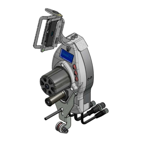
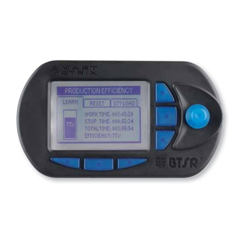
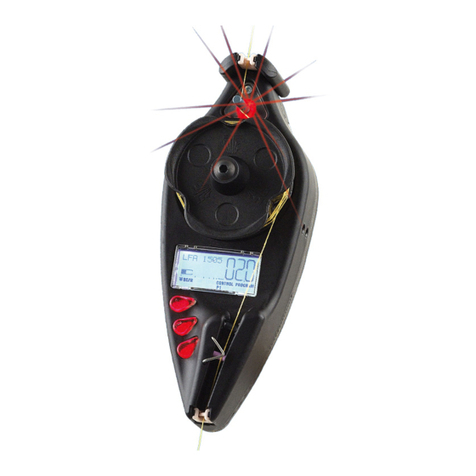
btsr WINDINGFEEDER User manual

WINDINGFEEDER
YARN CONTROL SYSTEM
Operating Manual
ENGLISH
Rev. 2.0 – -March 2011

WINDINGFEEDER – Rev. 2.0 – March 2011
Copyright - BTSR - All rights reserved.
This manual is intended for the users of WINDINGFEEDER yarn feeding devices. It is suggested to
carefully read the instruction reported on this manual before making the connections and use the
devices.
BTSR reserves the right to change at any time the contents of this manual, without notice.
For any technical or commercial problem, please contact your local BTSR dealer or call directly BTSR
customer service centre. We will be glad to meet your needs.
Thank you for your trust and good job.
The product described herein is compliant with the requirements of EMC 2004/108/EC.
All BTSR products are covered by patents and adopt exclusive, profitable and high tech.
Solutions.
WindowsTM is a registered trademark of Microsoft Corporation
BTSR® is a registered trademark “Best Technology Study & Research” of BTSR International S.p.A

Table of Contents
WINDINGFEEDER - i -
TABLE OF CONTENTS
INTRODUCTION
The ideal solution for yarn preparation machines...................................................................................................I.1
How to use this manual ..............................................................................................................................................I.2
Symbols used ...............................................................................................................................................................I.2
Reference Documentation ..........................................................................................................................................I.2
Chapter 1 - OVERVIEW’
System Components................................................................................................................................................... 1.1
Main Characteristics of WINDINGFEEDER Devices ........................................................................................... 1.1
Advantages obtained by using the WINDINGFEEDER devices........................................................................... 1.3
Advantages obtained by using the SMART MATRIX FEEDER Terminal combined with
WINDINGFEEDER Devices .................................................................................................................................... 1.4
Further Advantages obtained by using a PC or Notebook connected to WINDINGFEEDER devices
via serial line............................................................................................................................................................... 1.5
Chapter 2 – TECHNICAL DATA AND INSTALLATION
Technical Features .................................................................................................................................................. 2.1
Electrical Interface of WINDINGFEEDER Devices............................................................................................... 2.2
SMART MATRIX FEEDER – WINDINGFEEDER Connection......................................................................... 2.3
Input/otput signals function...................................................................................................................................... 2.3
PC – WINDINGFEEDER Connection..................................................................................................................... 2.4
D WINDINGFEEDER overall dimensions (in mm) ............................................................................................... 2.5
Instructions for Correct Yarn Threading................................................................................................................ 2.7
Chapter 3 – OPERATION
Operating Characteristics of WINDINGFEEDER Devices ................................................................................... 3.1
Symbols shown on LCD ............................................................................................................................................ 3.2
Functions Directly Available to the Textile Machine Operator............................................................................. 3.3
1) Alarm Reset......................................................................................................................................................... 3.3
2) Current Yarn Type and Application Reading...................................................................................................... 3.3
3) Exclusion and Re-inclusion of a WINDINGFEEDER Device............................................................................ 3.4
4) Control of Temperature and Current Absorbed by WINDINGFEEDER ............................................................ 3.4
Programming the WINDINGFEEDER Devices ..................................................................................................... 3.5
General Diagram of Simple Programming Environment......................................................................................... 3.5
Advanced Programming of WINDINGFEEDER Devices ..................................................................................... 3.6
General Diagram of P1÷P4 Advanced Programming Levels and Default Settings ................................................ 3.8
P1 Programming Level.............................................................................................................................................. 3.9
P2 Programming Level............................................................................................................................................ 3.12
P3 Programming Level............................................................................................................................................ 3.15
P4 Programming Level............................................................................................................................................ 3.17
Chapter 4 – WINDINGFEEDER TROUBLESHOOTING AND MAINTENANCE
Indications Provided by the Red LEDs on WINDINGFEEDER Device .............................................................. 4.1
Troubleshooting Table .............................................................................................................................................. 4.2
Ordinary Maintenance.............................................................................................................................................. 4.4
Repairs........................................................................................................................................................................ 4.4

Table of Contents
- ii - WINDINGFEEDER
Page intentionally left blank

Introduction
WINDINGFEEDER - I.1 -
INTRODUCTION
Congratulations for choosing a BTSR product.
With our WINDINGFEEDER yarn feeding devices, with or without the SMART
MATRIX FEEDER control unit, you got an innovative, unique solution able to
offer you multiple advantages concerning quality of your production.
The ideal solution for yarn preparation machines
The WINDINGFEEDER device comes from the experience built-up by BTSR in
the field of yarn feeling at constant tension.
The WINDINGFEEDER devices are in fact high precision measurement and
control instruments providing a real time display of the exact yarn tension and
guaranteeing, through an accurate adjustment, a constant tension feeding of the
yarn itself in every working condition. This occurs independently of the speed at
which the textile machine is running (either high or low speed) and the tension is
kept constant even when the yarn package tension is subject to change due to
environment conditions such as humidity, temperature, etc., or when the yarn
packages are gradually emptying during the normal working process.
The WINDINGFEEDER devices are fully programmable and can easily be
adapted to any kind of yarn or tension adjustment and to any operating speed of the
textile machine on which they are installed. Furthermore these devices are
manufactured using very high quality and precision electronic components which
guarantee an exact display of the yarn tension as well as an accurate real-time
control of the tension itself, exclusive characteristics of BTSR systems.
Thanks to its modularity characteristics, the WINDINGFEEDER device is
capable of managing not only the TS44.. tension sensor, but also the IS3.. image
scanning sensor, thus allowing the user to obtain a complete quality control for
what concerns both the yarn tension and the correct yarn running condition.
This is particularly important on doubling machines where multiple yarns are fed
using the same device, in order to stop the machine in case of breakage or lack of
one or more yarns.

Introduzione
- I.2 - WINDINGFEEDER
How to use this manual
This Operation Manual is divided into 4 Chapters.
Chapter 1 – Overview describes the main features, components and the operation
principle of WINDINGFEEDER devices.
Chapter 2 – Technical Data and Installation gives the necessary instructions to
install the devices.
Chapter 3 – Operation gives a detailed description of the necessary operations to
setup and program the WINDINGFEEDER devices according to the application
needs.
Chapter 4 – Troubleshooting and Maintenance provides a quick guide to solving
the main failures of WINDINGFEEDER devices.
Symbols used
Highlights notes, warnings and subjects to which the attention of the reader
should be directed.
Indicates a particularly sensitive situation which could have an effect
on the safety or proper operation of the system.
TENSION ERROR
All the items concerning the device programming menus, within this
manual, are always show in CAPITAL LETTERS.
Reference Documentation
For operating details about the programming/analysis and monitoring systems
available for WINDINGFEEDER device management, please refer to the
following BTSR manuals.
SMART MATRIX FEEDER Manual – Rev. 2.2 – Ed. 03/2008
PC-LINK KTF Manual– Rev. 2.0 – Ed. 09/2005
PC-LINK KTF Studio Manual – Rev. 1.0 – Ed. 03/2005
P1.2

Overview
WEENDINGFEEDER - 1.1 -
1 - OVERVIEW
System Components
The WINDINGFEEDER devices can be programmed and used either in individual
and autonomous way, or they can be connected to a control/programming SMART
MATRIX FEEDER terminal, thus obtaining a complete system providing further
levels of analysis, adjustment, control and speed-up of production cycles, as well as
statistical data processing, particularly useful to reach the quality and saving goals
stated in the Introduction of this manual.
The programming/monitoring unit may be either a dedicated BTSR terminal
(SMART SMATRIX FEEDER) or a Personal Computer operating under WindowsTM
environment with BTSR application software (PC-Link KTF).
The solution based on personal computer and PC-Link KTF software, besides a
greater operating flexibility, offers a set of additional functionalities which allow
you to customize the application according to your specific requirements (e.g. the
Tension Profiler) and to display/print in real time and in graphical form all the
significant data concerning the WINDINGFEEDER device functionality.
Moreover, using a Personal Computer or Notebook with the aid of PC-LINK KTF
Studio software running under WindowsTM environment, you can implement an
efficient analysis & monitoring system which allows you to find and correct even
the minimum critical conditions and behavior differences among the various
devices.
Main Characteristics of WINDINGFEEDER Devices
Full Digital Technology
The WINDINGFEEDER device is a fully high-tech digital instrument that allows
setting of the exact tension value at which you want to operate. The data setting is
done through a small three-button key-pad and a graphic LCD display.
In normal operating conditions the LCD provides a real time display of the exact
yarn tension (in grams) during the manufacturing process, the yarn consumption
speed (LFA) (in m/min) and, in graphical form, both the average and peak values of
the yarn tension.
The WINDINGFEEDER devices are controlled by two DSPs (Digital Signal
Processor) and by ASIC components (BTSR Patent) which provide great versatility
(parameters may be programmed depending on the various yarn processing
conditions)
The Full Digital Technology also allows performing a number of extremely
accurate controls on the device motor (absorbed current, speed, motor angular
position, etc.).
Temperature control
In addition, the operator may display at any time the internal temperature (in °C) of
both control board and motor, by pressing the Reset button.

Overview
- 1.2 - WINDINGFEEDER
An excessive increase of the temperature could infact indicate a wrong use of the
device; for this reason, the software on board of device performs a continuous
monitoring of the internal temperature.
If such temperature exceeds 100°C, an alarm message (ERROR °C) appears in the
graphic area of LCD, and the Stop output is activated.
Safety
Thanks to a configurable safety code, all parameters can only be changed by
authorized staff knowing such safety code.
External control
The WINDINGFEEDER device may easily be programmed also using the SMART
MATRIX FEEDER terminal which, thanks to its flexibility, allows programming
of many devices at a glance. Once you have chosen the desired working values on
a given machine, you will just transfer the selected setting data to the SMART
MATRIX FEEDER and then to other devices installed on different machines; all
this in about 1 second (i.e. the time needed to complete the data transfer).
User friendly installation and management
The WINDINGFEEDER is quite compact (290 x 86 x 94 mm). This permits you to
install several devices on the same machine with limited encumbrances. The device
has been designed bearing in mind not only the technological aspects, but also the
ergonomic ones. Thanks to these characteristics, the device can be perfectly fitted
within the machine structure, without compromising the machine spaces which are
usual to the operator.
Usable with any type of yarn
The WINDINGFEEDER device can work with a wide range of yarns, including
very thin yarns such as bare and covered elastomers, always guaranteeing a perfect
control of yarn tension values chosen by the user, which results in a high quality of
the manufactured product.
The WINDINGFEEDER device considerably reduces the preparation tasks, thanks
to a single self-threading ceramic eyelet that makes the operator job easier.
The tension value displayed on LCD indicates the actual tension with which the
device is working. This guarantees a constant and accurate monitoring of the
working process.
Easy to program
Possibility of viewing and selecting directly from the navigation menu the desired
application (rewind 1/2, warp 1/2, etc.) without the need of manually setting the
relevant parameters.

Overview
WEENDINGFEEDER - 1.3 -
Advantages obtained by using the WINDINGFEEDER devices
Constant yarn tension both when the machine speed changes and when the yarn
packages gradually get empty.
Best efficiency by eliminating the yarn breakage (tears and extratensions), and
possibility of working at the highest speed offered by the machine.
Possibility of working with a wide range of yarn types.
Accurate yarn feeding speed measurement (1 to 2,500 m/min) – (LFA m/min = Length
of Absorbed Yarn).
Possibility of using the yarn up to the complete package emptying.
Better machine efficiency.
Possibility of finding the best application conditions of WINDINGFEEDER device:
(No of coils to be wound around the roller, ideal programming values for parameters
etc), thanks to the continuous visualization, in graphic form, of both average and peak
values of yarn tension.
Possibility of handling up to a maximum of 16 sensors of the IS3x/TS series, for
doubling machine applications where more than one yarn must be simultaneously fed
(by means of WINDINGFEEDER) and controlled (by means of IS3x/TS).

Overview
- 1.4 - WINDINGFEEDER
Advantages obtained by using the SMART MATRIX FEEDER Terminal
combined with WINDINGFEEDER Devices
Using the SMART MATRIX FEEDER terminal connected to WINDINGFEEDER
devices you have the possibility of developing a wide range of functions which
facilitate the practical use of the installed WINDINGFEEDERs (immediate download
and upload of data), as well as displaying fundamental data, such as yarn consumed
and yarn tension.
Possibility of creating up to 99 “articles”, saving them to the Data Base for an easy
subsequent recall. Without the need of setting up new parameters, these will simply be
called from the Data Base and subsequently transferred to the WINDINGFEEDER
devices installed on textile machine.
Possibility of using the TARGET function (meter count) and the Stop output, when
reaching the amount of meters setup, with possible automatic bobbin change enabling
(autodoffing).
Possibility of controlling and quickly correcting the tension adjustments, thus
eliminating the defects due to irregular tensions, tears and wrong yarn unwinding.
Possibility of identifying the connected WINDINGFEEDERs using an automatic
numbering procedure (BTSR Patent).
For more details, please refer to the SMART MATRIX FEEDER operating
manual.

Overview
WEENDINGFEEDER - 1.5 -
Further Advantages obtained by using a PC or Notebook connected to
WINDINGFEEDER devices via serial line
With PC-LINK KTF Software
Using a Personal Computer connected to the WINDINGFEEDER devices through
either a RS232 serial port or an USB port, with the aid of BTSR PC-Link KTF
software, you may program in quick and intuitive way, all the operating parameters of
WINDINGFEEDERs devices; in addition, you may display, through a single synoptic
screen, the operating status of all connected systems, thanks to an easily interpretable
color code.
Possibility of associating each article with a “Tension Profiler” allowing you to
rapidly and effectively adapt the working parameters of WINDINGFEEDERs to your
specific application requirements.
Possibility of displaying and/or printing several graphics showing the real-time
dynamic variation of the significant operative items (such as yarn tension, current
absorbed by the motor, motor torque, etc.); this allows you to speed-up and optimize
the “tuning” of the whole system.
Possibility of updating the WINDFEEDERs software without having to physically
replace the microprocessor.
The following screen shots have a merely indicative purpose, i.e. to show the
characteristics of the PC-Link KTF software graphical interface.
For more detailed information, please refer to the PC-Link KTF operating
manual.
PC-Link KTF – Example of synoptic view with 20 WINDINGFEEDER devices
configured over 10 machine sections (2 devices for section).
- Devices 1 - 12 = Running
- Devices 13 - 14 = Stopped (STOP)
- Devices 15 - 20 = Not connected (COMM ERROR)

Overview
- 1.6 - WINDINGFEEDER
PC-Link KTF – Example of graphic showing the dynamic progress of yarn tension on
devices 1 and 2, plus real-time display of speed, torque %, current and temperature values.
PC-Link KTF – Example of graphic showing the dynamic progress of yarn tension, motor
torque and current absorbed by device 1.

Overview
WEENDINGFEEDER - 1.7 -
PC-Link KTF – Examples of WINDINGFEEDER device operation parameters
programming.

Overview
- 1.8 - WINDINGFEEDER
PC-Link KTF – Example of graphic screen showing the upload of working
parameters (style) to the WINDINGFEEDER devices.
With PC-LINK KTF Studio Software
Using the PC-LINK KTF Studio software or other application programs specifically
developed by BTSR, you will have the possibility of upgrading (via serial line) the
WINDINGFEEDER device firmware, without the need of physically replacing the
microprocessor. In addition, the PC-LINK KTF Studio software offers several analysis
and monitoring facilities that make easier the tuning of control parameters to the
production managers.
Possibility of displaying in real-time up to 4 control graphics related to as many
WINDINGFEEDER devices.
Possibility of displaying/saving and printing (for each graphic) up to 7 different
control parameters (work tension, min/max tension, motor torque, motor speed, inlet
tension).
Possibility of immediately checking the efficiency degree of WINDINGFEEDER
devices by comparing the yarn inlet tension (not regulated) with the outlet tension
(regulated by the WINDINGFEEDER device).
Possibility of checking (or comparing) the results obtained with two different versions
of device control firmware.
For more details, please refer to the PC-LINK KTF Studio operating manual.

Technical Data and Installation
WINDINGFEEDER - 2.1 -
2 – TECHNICAL DATA AND INSTALLATION
Technical Features
WINDINGFEEDER Device
Power supply voltage 24 VDC ± 10% or 24 VAC ± 20%
0.2 A (during normal operation);
1 A (under stress);
Maximum absorption
3 A (at start-up)
STOP Outputs: relay contacts (NO) 0.3 A 125 VAC
1 A 30 VDC
Opto-insulated Inputs 0-24 VDC
VIL Max 1.2 VDC
VIH Min 5 VDC
Max. voltage Iinputs,- Output) 30 VDC
Programmable yarn tension 0.5 ÷ 100.0 gr. (resolution 0.1 gr.) or
5 ÷ 1,000 gr. (resolution 1 gr.)
Depending on the type of TS44 sensor used
Programmable alarms 0.1 ÷ 10 sec.
Integrated keypad 3 push-buttons + STOP red LED
Signaling With LCD graphic display
Dimensions 290 x 86 x 94 mm
Operating temperature range 10° - 60 °C
Storage temperature -25° - +85° C
Tension range 0 / full scale
Useful tension range 0% - 95% full scale
Max applicable tension 10 times the full scale value
IS3x/TS Sensor
Power supply voltage 12 .. 24 Vdc ± 20%
Absorption 15 mA (max 20 mA)
STOP output NPN
STOP output protection Protection against over-voltages/short-
circuits
Maximum Current of STOP output 200 mA continuous; 500 mA peack
Reaction Delay Programmable from 5 to 1,000 msec
Sensitivity Programmable (10 levels)
Signaling With integrated LEDs
Dimensions (mm) 15 x 15 x 36,5 (Narrow) - 25 x 15 x 36.5 (Wide)
Operating temperature range 10° - 60 °C
Storage temperature -25° - +85° C
TS44/xxxyRW Sensor
Power supply voltage 12 .. 24 Vdc ± 10%
Absorption 20 mA (max)
Analogue Output 100 mV - 10V
Analogue output resistance 1K Ohm
Operating temperature range 10° - 50 °C
Storage temperature -25° - +85° C
Tension range 0 - fondo scala
Useful tension range 0% - 95% fondo scala
Max applicable tension 10 volte il fondo scala
Drift error (a) 0.05% / °C
Repeatability error (b) 0.5%
Max linearity error (c) 2% (0 - fondo scala)
Signaling Mediante LED integrati
Dimensions 50 x 25 x 12.5 mm

Technical Data and Installation
- 2.2 - WINDINGFEEDER
SMART MATRIX FEEDER Terminal
Power supply voltage 24 VDC ± 10%
Maximum absorption 100 mA
Dimensions 140 x 80 x 31 mm
Operating temperature range 10° - 60 °C
Storage temperature -25° - +85° C
LCD graphic display 80 x 40 mm
Integrated Touch-pad 6 buttons + rotary selector
Protection 2 fuses – 1.5A
Electrical Interface of WINDINGFEEDER Devices
TS44 Connector for TS44.. tension sensor connection
SM/IN - SN/OUT Connectors for WINDINGFEEDER device daisy chain connection
Ext Connector available for future expansions
UNICO Connector for intelligent accessory connection
IS3 Connector for IS3.. yarn image sensor connection

Technical Data and Installation
WINDINGFEEDER - 2.3 -
Input/output signals function
Inputs Function
P1P2 It causes a switching between P1 and P2 tensions (*)
The switch P2 →P1 only deletes the TARGET error.
RESET This signal activation causes the alarms reset.
EXC This signal activation causes a reset of the target internal counter.
Output Function
STOP1 It is activated when the Windingfeeder device generates an alarm.
STOP2 It is activated when the Windingfeeder device reaches the target.
(*) For more details about P1 e P2 tensions please refer to chapter 3 - Operation
Both: Inputs and Outputs can be programmed as normally open (NO) or normally closed (NC) contacts. The
programming is global, i.e. every input (and every output in the same way) operates as NO or NC, depending
on the selected option. For more details, please refer to chapter 3 – Operation – P4.7 SIGNAL POLARITY .
SMART MATRIX FEEDER – WINDINGFEEDER Connection
Concerning all electrical systems, it is a suggested rule to ensure that the ground cable
(GND) is connected to the device support.

Technical Data and Installation
- 2.4 - WINDINGFEEDER
PC – WINDINGFEEDER Connection
Concerning all electrical systems, it is a suggested rule to ensure that the ground cable
(GND) is connected to the device support.

Technical Data and Installation
WINDINGFEEDER - 2.5 -
WINDINGFEEDER overall dimensions (in mm)

Technical Data and Installation
- 2.6 - WINDINGFEEDER
WINDINGFEEDER Unit
A Ceramic element for coil separation – ø 5
B Allen screw for ceramic element inclination adjustment
C Allen screw for ceramic element eccentric support adjustment
TS44/xxxyRW Tension Sensor
A Fastening hole with M4 x 20 screw
B Loading cell (tension sensor)
Note: the TS44.. device may automatically carry out the offset function upon special command issued by
WINDINGFEEDER device (see OFFSET AUTO parameter on P3 programming level)
A
B
C
TS44
Table of contents
Other btsr Control System manuals

btsr
btsr SMART KTF 2000 User manual

btsr
btsr DIAPERFEEDER IP54 DUOLOOP User manual

btsr
btsr TS5 Series User manual

btsr
btsr MULTIFEEDER User manual

btsr
btsr SMART 3000TW User manual

btsr
btsr SMART MATRIX WINDINGFEEDER User manual

btsr
btsr SMART MATRIX MTC User manual

btsr
btsr SMART MATRIX TWIST User manual

btsr
btsr SMART KNIT User manual

btsr
btsr SMART 200 MTC User manual
Popular Control System manuals by other brands

Jäger
Jäger ADwin-Pro System and hardware description

Mitsubishi Electric
Mitsubishi Electric TC-24A installation manual

HydroQuip
HydroQuip BALBOA CS6000B Series Operation manual

Carbide 3D
Carbide 3D SHAPEOKO 3 Assembly guide

Astral Pool
Astral Pool 27818 Installation and maintenance manual

V-ZUG
V-ZUG Card-System 1 operating instructions