PRE-INSTALLATION SPECIFICATIONS
Preparing the Space
NOTE: Make sure floor under appliance is level with surrounding finished floor. Protect finished floor with masonite,
plywood, 1/8” (3 mm) pressed fiberboard, or some other suitable material before moving the appliance across it.
Electrical Requirements
To rough in the electrical outlet following the Pre-Installation Specifications. You will need a 115 Volt, 60 Hertz elec-
trical supply, with a dedicated 15 Amp fuse / circuit breaker. Also be sure to follow any local codes that apply.
The appliance comes with a three-prong grounded plug power supply cord. The appliance must be plugged into a
mating three-prong wall receptacle grounded in accordance with the National Electrical Code and local codes.
Plumbing Requirements
The unit has an automatic ice maker with a water filtration system, which operates on water pressure between 35
psi (2.4 bar) and 120 psi (8.3 bar). If the filtration system is bypassed, water pressure must be maintained between
20 psi (1.4 bar) and 120 psi (8.3 bar).
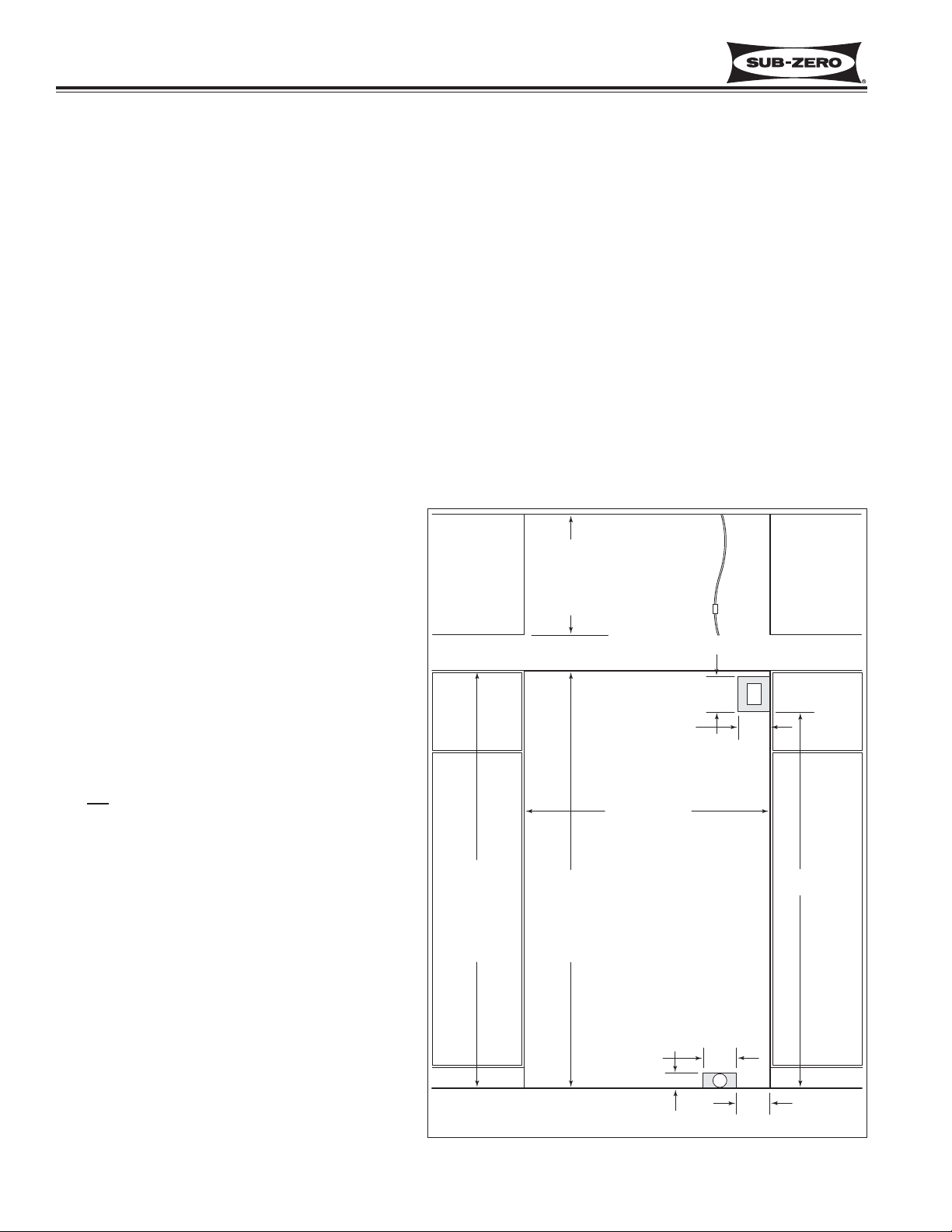
Rough in the water supply using 1/4" OD copper
tube. The water line should be routed up through the
floor within 1/2" (13 mm) from back wall and no high-
er than 3" (76 mm) off the floor. If coming through
the wall, make sure the water line is no more than 3"
(76 mm) from the floor. Regardless of the routing,
allow 3' (914 mm) excess copper tubing outside the
wall or floor for easy connection to the unit.
Locate water supply line within shaded area indicat-
ed in the Pre-Installation Specifications diagram.
Use an easily accessible shut-off valve between the
water supply and unit. Do not use self-piercing
valves. A saddle valve kit (part #4200880) is avail-
able from a Sub-Zero dealer.
It is not recommended that the appliance be con-
nected to a softened water supply. Chemicals, such
as salt from a malfunctioning softener, can damage
the ice maker and lead to poor ice quality. If a soft-
ened water supply cannot be avoided, be sure the
softener is well maintained and operating properly.
NOTE: Do not use with water that is microbiological-
ly unsafe or of unknown water quality without ade-
quate disinfection before or after the system.
Systems certified for cyst reduction may be used on
disinfected waters that may contain filterable cysts.
NOTE: Installations must meet local plumbing code
requirements.
NOTE: A reverse osmosis system can be used, if
there is constant water pressure of 20 psi (1.4 bar) to
120 psi (8.3 bar) supplied to the unit at all times. In
this application, the integrated water filtration system
must be set to bypass mode.
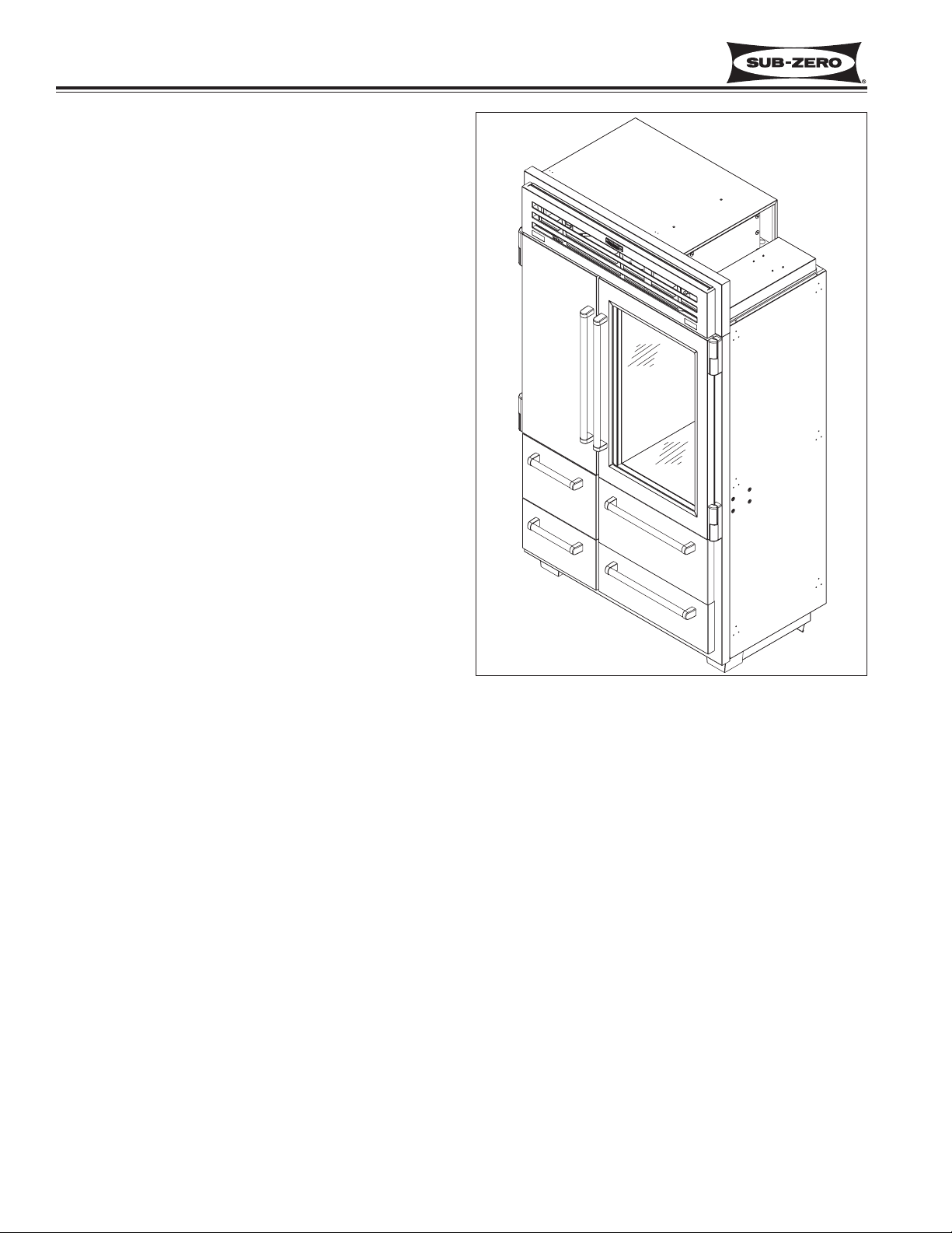
Installation Information Pro-Series (
Pro-Series (648PRO)
648PRO)
2-4
#3758440 - Revision B - November, 2006