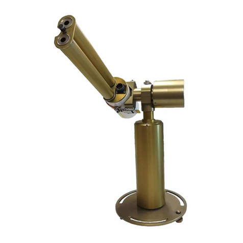
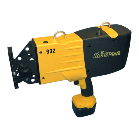
SubSurface Instruments AML PRO User manual

SUBSURFACE
INSTRUMENTS, INC.
AML PRO™
OPERATOR’S
MANUAL
www.ssilocators.com
• Originally designed by NASA engineers
for use in lunar exploration
• Re-designed to find buried objects and pipes of all kinds
including PVC, PE, Rubber, Steel, etc.
• Patented, Radio Frequency Technology
• Lightweight, Durable Construction

INSPECTION OF THE AML PRO
DO NOT open the housing of this unit,
doing so will damage the transmission
and receiving antennas. There are no
user serviceable parts inside. Opening
the sealed case will void the warranty.
If maintenance, tuning, or repair
becomes necessary, contact:
SubSurface Instruments, Inc.
email: info@ssilocators.com
Telephone: 920-347-1788 or
Or by mail:
SubSurface Instruments, Inc.
1230 Flightway Drive
De Pere, WI 54115 USA
AML SAFETY INFO
READ & OBSERVE ALL INSTRUCTIONS
Save these instructions for future reference.
2
Proudly Made in the USA

Laser
This product uses a Class
II/2M laser. Avoid direct
exposure to the beam.
Do not direct the laser beam at
People or animals. Do not
stare into the laser beam. The
AML Pro produces Laser Class
II/2M laser radiation according
to IEC 60825-1.
Looking directly into the
laser beam - especially with
optical instruments such as
binoculars or magniers - can
permanently damage the eye.
This is a professional tool, not
a toy. It should not be used by
children.
OPERATION
Only use this equipment for
the purpose specied by the
manufacturer. Any misuse may
void the warranty.
READ & OBSERVE SAFETY WARNINGS
Save these instructions for future reference.
D
F
I
E
P
English
German
French
Italian
Spanish
Portuguese
3

This unit contains a control circuit
board and an antenna circuit board
which directs the center transmitter
as well as independent left and right
signal receivers.
A powerful 2.45 Ghz radio frequency
locates density differences thru the
transmission and reception of UHF
signals.
The unit locates objects by analyzing
differences in material densities.
Objects or geometries create phase
differences in the return signal, which
are then interpreted by the highly
advanced circuitry.
HOW THE AML PRO WORKS
User Reference - Scanning QR Codes
The AML Pro has several QR Codes placed on the blade’s face.
Scan these codes for more operator information, and for continu-
ing updates provided by the manufacturer. AML Pro additional
information can be accessed from your smart phone using a stan-
dard QR code App. For more information on how to download and/
or use a QR code App., visit the App. store on your smart phone.
Reference materials
can also be accessed by visiting the SSI web-
site at ssilocators.com.
4

FCC
Currently under Test Certication.
IC (Industrie Canada)
Currently under Test Certication.
CE (European Countries)
Currently under Test Certication.
FCC/IC/CE STATEMENTS
5

AML PRO FEATURES
12
34
5
6
7
8
11
10
9
Backside view of unit
12
6
1a

1) EASY BATTERY ACCESS
The AML Pro is powered by either a convenient 9-volt battery
system (1), or by a rechargeable lithium battery pack (1a).
2) ERGONOMIC HANDLE
The ergonomically designed handle allows the operator to hold the
AML Pro for extended periods of time in all weather conditions.
3) CONTROL PANEL
There are six function buttons on the AML Pro control panel, these
buttons will provide you with the ability to navigate through the
Menu Screen, as well as having access to the many features on
your AML Pro Unit. Functions include: ON/OFF, TX (Transmitter),
MENU, DOWN ARROW, UP ARROW, SEL (Select).
4) RIGHT SIDE & LEFT SIDE TARGET INDICATORS
LED target indicators identify when an object has been located,
signifying that the object is parallel with the AML Pro. Digital target
indicators are displayed at the bottom of the main screen on
the LCD digital display and work in unison with the right and left
receivers to indicate an object’s presence, and to place its location.
5) DIGITAL BACKLIT DISPLAY
A high contrast, backlit digital display provides superior visibility in
both direct sunlight and dark environments.
6) LIGHTWEIGHT, DURABLE CONSTRUCTION
The electronic circuitry of this unit is housed in a tough, water-
resistant, high-impact ABS enclosure. This enclosure helps to
protect the sensitive electronic components. It does not protect the
unit from abuse or careless misuse. Treat this unit as a scientic
instrument. Keep it stored in the foam-insulated case when not in
use.
7) ULTRA-HIGH FREQUENCY (UHF) RADIO TRANSMITTER
An UHF transmitter delivers the intensity of the UHF signal as it is
aimed at its intended target.
7

8) LASER TARGET INDICATOR
A red laser indicator identies the target position when an object
has been detected; and an audible signal is emitted.
9) ULTRA-HIGH FREQUENCY (UHF) RADIO RECEIVERS
The receivers, capture the returning UHF reection with antennas
on both ends of the unit. Positioning the unit parallel to an object’s
edge will illuminate both LED lights, the laser target indicator, the
target indicators on the LCD Digital Display and activate an audio
signal. 10
- HEAD PHONE JACK-PORT
10) NOISE ISOLATING HEADPHONES
Lightweight headphones, with noise isolating qualities; soft, closed
cushions can be used as an option when in a noisy environment.
11) HEADPHONE JACK-PORT*
Insert headphone jack into the headphone port for operation in
noisy environments if necessary.
12) USB PORT*
The USB Port has several functions such as connecting the
optional external lithium battery supply to the USB Port for
extended power, and for uploading or downloading diagnostic
information, including GPS log les.
*Important:
ALWAYS turn the AML Pro OFF before connecting to the auxiliary
battery pack or the headphone port. Failure to do so, might result in
a frozen screen and malfunction of the Unit, in such case turn the
AML Pro off wait for 10 seconds and then turn it back on. Also, turn
the AML Pro off before the auto shutoff setting for low battery turns
the Unit off. The lithium battery pack will provide a minimum of 12 hours
of continuous usage before needing to be re-charged. There are several
USB ports on the battery pack that can be used to power additional
pieces of equipment all at the same time, such as a cellphone or any
other device that requires a USB power supply. The battery pack can be
placed in any suitable holder or simply carried in the operator’s pocket.
8

RTC sats
DEG
SEN
09
86
17
27 5716
044 4494 N27
088 6298 W07
Latitude
Longitude
GPS
Location
Time Status Messages
Angle º
Sensitivity
Phase Bars
STATUS MESSAGES
POWER EVENTS
OPERATE
STANDBY
USB PWR
BAT PWR
LOW BAT
AML OFF
AUTO OFF
LOW BAT
AUTO SLEEP
RF transmitter on
RF transmitter off
External battery plugged in
Internal battery plugged in
Low battery warning
SLEEP Wake up by moving the unit
5 seconds to shutdown
5 seconds to shutdown
CLK BAT Internal clock battery low
FLOW CHART
MAIN SCREEN INTERFACE
GENERAL STATUS MESSAGES
9

CALIBRATION EVENTS
RF TEST WAIT
PASS
FAIL
GPS EVENTS
SATS
LOGGED
NO LOCK
Number of GPS Satellites
Log record filed to memory
No GPS satellites found
FULL
DISCARD
EMPTY
No room for new logs
Erase records from memory
No records saved in memory
System ready
Perform RF calibration
System ready
Repeat calibration
RF CAL WAIT
PASS
FAIL
GENERAL STATUS MESSAGES
10

OPERATION OF THE AML PRO
OPERATOR FUNCTION CONTROLS
There are six function buttons on the AML Pro control panel:
1. On/Off - Press and hold the On/Off Button to turn the
unit On or Off.
2. TX (Transmitter) - Press the TX Button to turn the
transmitter On or Off.
3. Menu - Press the Menu Button to bring up the Menu
Screen. There are two pages of Menu Screens.
4. Down Arrow - Use the Down arrow to either adjust the
sensitivity level down, or to move the cursor down once
inside of the menu screens.
5. Up Arrow - Use the Up arrow to either adjust the
sensitivity level up, or to move the cursor up once inside
of the menu screens.
6. Sel - Press the Sel button to either activate the GPS
Functions, or to Select the Menu option once inside of
the menu screens.
Press the On/Off Button. The SSI Logo will appear
followed by a screen that will display the current software
revision. The AML Pro will perform a self-check; when it is
completed, the MAIN SCREEN will appear.
Ver 4 2
1
Figure 11-1
Figure 11-2
11

12
On the left side of the screen
Time and GPS:
RTC (Real Time Clock)
Time is read in hours, minutes, and
seconds.
GPS (Global Positioning System)
Digits on the screen are read in
degrees, minutes, and seconds,
Latitude: N for North of the equator or
S for South of the equator. Longitude:
E for East of the Prime Meridian or W
for West of the Prime Meridian.
On the right side of the screen
Status Lines:
SATS (Satellites) refers to the number
of satellites in which the AML Pro is
communicating. To increase the level
of accuracy it is preferable to use 7 or
more satellites.
DEG (Degree) As referenced from the
blade face angle of the AML Pro.
SEN (Sensitivity Level) shows the
selected SENSITIVITY Level of the
AML Pro (1 to 32). Use the UP or
DOWN arrow Buttons to set the SEN
level from 1 to 32 with 32 being the
most sensitive.
Digital Target Indicators
The target indicators appear at the
bottom of the screen. Both bars
will come together when a target is
positively identied.
TX (Transmitter)
Press the TX Button to turn the
transmitter ON or OFF. When the
transmitter is OFF, a STANDBY
message on the right side of the
screen will appear
(see gure 12-
4)
. When the transmitter is turned
back on, the message will change to
OPERATE (see gure 12-5).
RTC sats
DEG
SEN
09
86
17
27 5716
044 4494 N27
088 6298 W07
RTC sats
DEG
SEN
09
86
17
27 5716
044 4494 N27
088 6298 W07
RTC sats
DEG
SEN
09
86
17
27 5716
044 4494 N27
088 6298 W07
RTC OPERATE
DEG
SEN
86
17
27 5716
044 4494 N27
088 6298 W07
RTC STANDBY
DEG
SEN
86
17
27 5716
044 4494 N27
088 6298 W07
RTC OPERATE
DEG
SEN
86
17
27 5716
044 4494 N27
088 6298 W07
RTC STANDBY
DEG
SEN
86
17
27 5716
044 4494 N27
088 6298 W07
Figure 12-2
Figure 12-4
Figure 12-3
Figure 12-5
Figure 12-1

> SPEAKER VOLUME
The AML Pro has a built-in internal
speaker. Use the UP ARROW or
DOWN ARROW Buttons to place
the cursor on SPEAKER VOLUME.
Press the SELECT Button to raise
the volume level in single increments
from 0 to 3, with 0 being MUTE and 3
being the highest level.
> PHONES VOLUME
(Headphone Volume)
The headphone jack allows the
operator to listen to audio signals
with noise isolating headphones
(included). Use the UP ARROW or
DOWN ARROW Buttons to place
the cursor on PHONES VOLUME.
Press the SELECT Button to raise
the volume level in single increments
from 0 to 3, with 0 being MUTE and
3 being the highest level. If you
continue to press SELECT, it will loop
the selection until the MENU Button
is pressed for saving the setting and
exiting the MENU screens.
Press the MENU Button to show the AML Pro selectable functions and settings.
NOTE: The MENU will time out after 30 seconds if no changes are made. Either
press the Menu button, or let the MENU time out to save changes. If the unit is
turned off while in the menu screen, it will NOT save the changes recently made.
Continuing to press SEL (select) button will conveniently loop the selection until
reaching desired level. Press the MENU Button to save the setting and exit the
MENU screen.
AML PRO MENU SETTINGS
13
speaker volume
phones volume
auto sleep sec
auto off min
check calibration
factory settings
2
2
10
05
0
0
Figure 13-1
>
speaker volume
phones volume
auto sleep sec
auto off min
check calibration
factory settings
2
2
10
05
0
0
Figure 13-2
>

14
> AUTO SLEEP SEC (Seconds)
Use the UP ARROW or DOWN
ARROW Buttons to place the cursor
on AUTO SLEEP SEC. Press the
SELECT Button to set the AUTO
SLEEP SEC delay from 0, 10, 20 or
30 seconds. This function places the
AML Pro in sleep mode, or pause,
once the unit has stopped sensing
motion. When the AML Pro goes into
AUTO SLEEP SEC mode, the unit
automatically stops, but is ready to
start again when the unit is moved or
put into motion. This helps conserve
battery power. Select 0 to disable the
AUTO SLEEP SEC function. Press
the MENU Button to lock the setting.
> AUTO OFF MIN (Minutes)
Use the UP ARROW or DOWN
ARROW Buttons to place the cursor
on AUTO OFF MIN. Press the
SELECT Button to set the AUTO OFF
MIN delay to 0, 5, 20, or 30 minutes.
Select 0 to disable the AUTO OFF
MIN function. The AUTO OFF MIN
function automatically shuts the
AML Pro completely OFF when the
unit senses that it is not in use. This
function conserves battery power.
speaker volume
phones volume
auto sleep sec
auto off min
check calibration
factory settings
2
2
10
05
0
0
Figure 14-1
>
speaker volume
phones volume
auto sleep sec
auto off min
check calibration
factory settings
2
2
10
05
0
0
Figure 14-2
>

> CHECK CALIBRATION (Outside)
Use the UP ARROW or DOWN
ARROW Buttons to place the cursor
on CHECK CALIBRATION. Press
the SELECT Button. Use the UP or
DOWN Buttons to move the cursor
to 1. Press the SELECT Button. The
STATUS Line will read RF TEST.
Point the AML Pro towards
unobstructed sky at a 45 degree
angle (+/- 10 degrees) within 10
seconds. If this is not done, the AML
Pro will return to normal run time. If it
is done within 10 seconds, the AML
Pro will take a 3 seconds “snapshot”
of the RF Board signal and display
either a PASS or FAIL message on
the STATUS Line. No modications
to the RF signal can be made from
this function selection. It is a PASS/
FAIL status test only. Use the CHECK
CALIBRATION test to verify that
the RF Board is operating within
specications.
> FACTORY SETTINGS
Use the UP ARROW or DOWN
ARROW Buttons to place the cursor
on FACTORY SETTINGS. Press the
SELECT Button to change to 1. Press
the MENU Button to save setting.
The FACTORY SETTINGS returns
all items in the rst menu screen
of the AML Pro to the settings and
specications as originally set at the
factory. All memory data will be erased
if the unit is reset to factory settings.
15
speaker volume
phones volume
auto sleep sec
auto off min
check calibration
factory settings
2
2
10
05
0
0
RTC RF test27 5716
RTC RF CAL27 5716
RTC wait27 5716
RTC pass27 5716
RTC fail27 5716
RTC RF test27 5716
RTC RF CAL27 5716
RTC wait27 5716
RTC pass27 5716
RTC fail27 5716
RTC RF test27 5716
RTC RF CAL27 5716
RTC wait27 5716
RTC pass27 5716
RTC fail27 5716
RTC RF test27 5716
RTC RF CAL27 5716
RTC wait27 5716
RTC pass27 5716
RTC fail27 5716
speaker volume
phones volume
auto sleep sec
auto off min
check calibration
factory settings
2
2
10
05
0
0
speaker volume
phones volume
auto sleep sec
auto off min
check calibration
factory settings
2
2
10
05
0
0
Figure 15-1
Figure 15-2
Figure 15-3
Figure 15-4
>
>
>

16
> TIME ZONE SET
Use the UP ARROW or DOWN
ARROW Buttons to scroll through the
dropdown menu.
Set the TIME ZONE SET to local time.
Setting the TIME ZONE SET utilizing
the Time Zone Set Table (gure 17-1)
will provide the unit with accurate local
time within the Time Zone that the unit
is operating.
The AML Pro maintains a Real Time
Clock (RTC), that can be automatically
synchronized to Global Positioning
System (GPS) time. RTC is the user’s
local time while GPS is referenced to
Universal Time Coordinated (UTC)
based in Greenwich, England.
There are 24 Time Zones. Find the
zone in which the unit will be operating
(see gure 17-1) and enter the time
off-set value from the Time Zone Set
vs. Local Time Table. After the Time
Zone Off-set value is entered and
saved, the RTC will be updated the
next time a GPS signal is acquired.
For those parts of the world with
a nonstandard off-set (30 or 45
minutes), the local clock time
synchronizing can be disabled by
entering a value of 24 into the TIME
ZONE SET.
The AML Pro does not automatically
shift the off-set for Daylight Savings
Time, add one(1) to your Time Zone
Set to adjust the time manually. This
time change will have to be re-entered
manually to come back from Daylight
Savings Time. The TIME ZONE SET
will have to be reset if the AML Pro
is transferred for use in other time
zones.
Time zone set
Calibrate
backlight off/on
00
0
1
Time zone set
Calibrate
backlight off/on
24
0
1
Figure 16-1
Figure 16-2
>

TIME ZONE WORLD MAP
17
001413 0115 0216 0317 0418 0519 0620 0721 0822 0923 10 11 12 12
SET
OFF-SET
SET
OFF-SET
The above Table shows the TIME ZONE SET value versus LOCAL TIME.
To set the Real Time Clock (RTC) on your AML Pro unit using the value table located at the bottom of this map, enter the two digit OFF-SET value (00 - 23) that is relative to the
Time Set value of the region where the AML Pro is going to be used. The RTC will be updated the next time a GPS lock signal is acquired.
Figure 17-1

18
> CALIBRATE
(Radio Frequency Calibration)
The CALIBRATE function recalibrates
the RF Board from backup les in the
microprocessor. CALIBRATE returns
the RF Board to its original condition.
Use the following procedure to
calibrate the RF Board:
1. With the unit outside, use the
UP or DOWN arrows to highlight
CALIBRATE.
2. Press SEL Button. The 0 in the
CALIBRATE eld will turn to 1.
3. Press MENU Button to exit the
CALIBRATE eld and to save the
setting.
NOTE: Once the CALIBRATE procedure is
selected the procedure must be completed
within 10 seconds, otherwise the process
will time out and return to the MENU
screen.
4. The MENU screen will return
to the MAIN screen. Check the
DEG Status Line on the MAIN
screen and hold the unit at a 45
degree angle (± 10 degrees) to
an unobstructed sky within 10
seconds.
5. The MAIN screen will show a WAIT
message. Hold the unit still while
pointed at an unobstructed sky and
allow it time to recalibrate.
6. Once the unit is recalibrated the
MAIN screen will show a PASS or
FAIL message.
7. Repeat the procedure if a FAIL
message is indicated.
> BACKLIGHT ON/OFF
Use the UP or DOWN arrows to place
the cursor on BACKLIGHT ON/OFF.
Press the SELECT Button to change
the 0 to 1 to turn the BACKLIGHT OFF.
The BACKLIGHT can be turned ON
or OFF. Turning the BACKLIGHT OFF
helps conserve battery power. Press the
MENU Button to save the setting.
Time zone set
Calibrate
backlight off/on
00
0
1
Figure 18-1
>
Time zone set
Calibrate
backlight off/on
00
0
1
Figure 18-3
>
RTC RF test27 5716
RTC RF CAL27 5716
RTC wait27 5716
RTC pass27 5716
RTC fail27 5716
RTC RF test27 5716
RTC RF CAL27 5716
RTC wait27 5716
RTC pass27 5716
RTC fail27 5716
RTC RF test27 5716
RTC RF CAL27 5716
RTC wait27 5716
RTC pass27 5716
RTC fail27 5716
RTC RF test27 5716
RTC RF CAL27 5716
RTC wait27 5716
RTC pass27 5716
RTC fail27 5716
Figure 18-2

An EVENT MESSAGE indicates a change within the system. Any change within
the system will be indicated by an audible notication (boink) and will display
on the STATUS line, located in the upper right corner of the DIGITAL DISPLAY,
for 3 seconds. There are three categories of EVENT MESSAGES: POWER,
LOGGING, RF CAL (Radio Frequency Calibration).
RTC sats
DEG
SEN
09
86
17
27 5716
044 4494 N27
088 6298 W07
RTC usb pwr
DEG
SEN
86
17
27 5716
044 4494 N27
088 6298 W07
RTC bat pwr
DEG
SEN
86
17
27 5716
044 4494 N27
088 6298 W07
RTC low bat
DEG
SEN
86
17
27 5716
044 4494 N27
088 6298 W07
RTC aml off
DEG
SEN
86
17
27 5716
044 4494 N27
088 6298 W07
RTC sats
DEG
SEN
09
86
17
27 5716
044 4494 N27
088 6298 W07
RTC usb pwr
DEG
SEN
86
17
27 5716
044 4494 N27
088 6298 W07
RTC bat pwr
DEG
SEN
86
17
27 5716
044 4494 N27
088 6298 W07
RTC low bat
DEG
SEN
86
17
27 5716
044 4494 N27
088 6298 W07
RTC aml off
DEG
SEN
86
17
27 5716
044 4494 N27
088 6298 W07
RTC sats
DEG
SEN
09
86
17
27 5716
044 4494 N27
088 6298 W07
RTC usb pwr
DEG
SEN
86
17
27 5716
044 4494 N27
088 6298 W07
RTC bat pwr
DEG
SEN
86
17
27 5716
044 4494 N27
088 6298 W07
RTC low bat
DEG
SEN
86
17
27 5716
044 4494 N27
088 6298 W07
RTC aml off
DEG
SEN
86
17
27 5716
044 4494 N27
088 6298 W07
EVENT MESSAGES
POWER EVENTS
USB PWR (Universal Serial Bus Power)
The USB PWR indicates when the
auxiliary battery pack is connected to
the AML Pro. Turn the AML Pro Unit
OFF before connecting the external
battery pack. Generally the auxiliary
battery pack will provide 12 hours
or more of continuous operation.
It’s recommended to use the AML
Pro with fresh 9-volt batteries in the
battery holder for back up.
BAT PWR (Battery Power)
The BAT PWR event indicates that the
AML Pro is operating on the internal
alkaline batteries.
LOW BAT (Low Battery)
The LOW BAT event indicates that
the internal alkaline batteries are
becoming too weak. The LOW BAT
event indicator applies only to the
alkaline battery sleeve located in the
handle of the AML Pro. The external
battery pack will shut the unit off
without a warning, that’s why is
recommended to have a fresh 9-volt
battery sleeve in the AML handle.
AML OFF (AML Pro Shutdown)
The AML Pro will automatically shut
down once the LOW BAT condition
drops the supply voltage below 6.5v
DC. All data previously recorded
prior to shutdown will be preserved in
memory. 19
Figure 19-1
Figure 19-2
Figure 19-3
RTC sats
DEG
SEN
09
86
17
27 5716
044 4494 N27
088 6298 W07
RTC usb pwr
DEG
SEN
86
17
27 5716
044 4494 N27
088 6298 W07
RTC bat pwr
DEG
SEN
86
17
27 5716
044 4494 N27
088 6298 W07
RTC low bat
DEG
SEN
86
17
27 5716
044 4494 N27
088 6298 W07
RTC aml off
DEG
SEN
86
17
27 5716
044 4494 N27
088 6298 W07
Figure 19-4

20
LOGGING EVENTS (GPS)
SATS (Satellites)
The SATS line indicates the number
of satellites in which the AML Pro is
communicating. To increase the level
of accuracy it is preferable to use 7 or
more satellites.
LOGGED (Logged Information)
A LOGGED event indicates that
information has been stored into the
memory of the AML Pro. The screen
will display a NO LOCK message if
less than 3 satellites are found. A LOG
is a “Snap Shot” of the information
recorded by the AML Pro thus far. This
information is recorded and indexed
by the memory, every time the SEL
button is pressed. It includes longitude
and latitude coordinates, day-month-
year, hour-minute-second, and the
number of communicating satellites.
FULL (Memory Full)
The AML Pro memory can store up to
300 records. A FULL event indicates
that the memory is full and no more
information will be recorded. A FULL
event will be accompanied with an
audible alert and a fault message in
the STATUS Line. When the memory
is full, the operator can either connect
the AML Pro to a computer and
download the information, thereby
emptying the AML Pro memory, or
DISCARD records to make room for
more.
DISCARD (Delete Information)
Press and hold the SELECT Button
for three seconds to delete the last
recorded information. You can Discard
information at any point while in GPS
Mode, even when the memory is not
full. Once all information has been
deleted, the screen will display an
EMPTY message in the STATUS line.
RTC no lock
DEG
SEN
86
17
27 5716
000 0000 N00
000 0000 W00
RTC logged
DEG
SEN
86
17
27 5716
044 4494 N27
088 6298 W07
RTC full
DEG
SEN
86
17
27 5716
044 4494 N27
088 6298 W07
RTC discard
DEG
SEN
86
17
27 5716
044 4494 N27
088 6298 W07
RTC empty
DEG
SEN
86
17
27 5716
044 4494 N27
088 6298 W07
clk bat
DEG
SEN
27 5716
4494 N27
6298 W07
RTC
044
088
86
17
Figure 20-3
Figure 20-2
Figure 20-4
Figure 20-5
RTC sats
DEG
SEN
09
86
17
27 5716
044 4494 N27
088 6298 W07
RTC usb pwr
DEG
SEN
86
17
27 5716
044 4494 N27
088 6298 W07
RTC bat pwr
DEG
SEN
86
17
27 5716
044 4494 N27
088 6298 W07
RTC low bat
DEG
SEN
86
17
27 5716
044 4494 N27
088 6298 W07
RTC aml off
DEG
SEN
86
17
27 5716
044 4494 N27
088 6298 W07
Figure 20-1
Table of contents
Other SubSurface Instruments Measuring Instrument manuals
