Succeeder SF-8100 User manual
1
Beijing SUCCEEDER Technology Development Co., Ltd.
SF-8100 Automated Coagulation Analyzer

2
1. Table of Contents
1. Table of Contents................................................................................................................................2
2. Warnings and Cautions ...................................................................................................................5
2.1. General Warnings...........................................................................................................................5
2.2. Safety of Login ..............................................................................................................................5
2.3. Warning before use ........................................................................................................................5
2.4. Quality Commitment .....................................................................................................................6
3. Circuit diagram and description.....................................................................................................7
3.1. Power module ................................................................................................................................7
3.2. Movement module .........................................................................................................................8
3.3. Sensor module................................................................................................................................8
3.4. Liquid flow module........................................................................................................................8
4. Technical specification ...................................................................................................................10
5. Description of device......................................................................................................................11
5.1. Intended Use ................................................................................................................................11
5.2. Application...................................................................................................................................11
5.3. Principle of clotting method.........................................................................................................11
5.4. Chromogenic substrate method....................................................................................................12
5.5. Immunoturbidimetric Method......................................................................................................12
5.6. Procedure Description..................................................................................................................13
6. Installation instruction...................................................................................................................14
6.1. Appearance; .................................................................................................................................14
6.2. Parts Description:.........................................................................................................................16
6.3. Cuvette supply system; ................................................................................................................19
6.4. Carry-Handles;.............................................................................................................................20
6.5. Work platform requirement;.........................................................................................................20
6.6. Unpack machine...........................................................................................................................21
6.7. Parts Release................................................................................................................................23
6.8. Connection...................................................................................................................................25
6.9. Cuvette rolls Installation..............................................................................................................26
6.10. Connect to computer. ...................................................................................................................28
6.11. Software installation. ...................................................................................................................29
6.12. Software introduction...................................................................................................................33
6.13. Routine test ..................................................................................................................................34
7. Maintenance ...................................................................................................................................36
7.1. Environment: ...............................................................................................................................36
7.2. Placement:....................................................................................................................................36
7.3. Communication analyzer .............................................................................................................36

3
7.4. Daily maintenance .......................................................................................................................38
8. Storage ............................................................................................................................................39
9. Troubleshooting..............................................................................................................................40
10. Symbols...........................................................................................................................................44
11. Circuit description & map.............................................................................................................45
12. Special tools ....................................................................................................................................46
13. Spare part list .................................................................................................................................47
14. Index................................................................................................................................................48
4
Thank you for purchasing our product
Read this manual carefully before use.
Model: SF-8100
Name: Automated Coagulation Analyzer
Manufacturer: Beijing Succeeder Technology Development Co., Ltd
Service hotline: Please contact with local authorized representative.
Fax: +86 -10-89701711
Address:Tower 1A, No. 27 Chuangxin Road, Changping District, Beijing 102200, China
Postcode: 102200
http://www.succeeder.com.cn
Service e-mail: aftersales@succeeder.com.cn
INFORMATION ABOUTAUTHORISED REPRESENTATIVE
Name:
Tel:
Fax:
Address:
Please send us information below for better service.
User Name:
Laboratory Name:
Instrument SN No:
Operator:

5
2. Warnings and Cautions
2.1. General Warnings
Read before first-use or installation. Failure to follow the recommended instructions will
adversely affect the safety and effectiveness of the SF-8100 analyzer system.
Succeeder shall not be held responsible if the procedures described in this manual are not strictly
observed, or if procedures not described in this document are used. Read the SF-8100 Operator’s
Manual carefully and respects all the instructions given therein.
With regard to the handling of test reagents, calibrator plasmas, control plasmas and patients’
plasmas, read carefully the package inserts provided in the relevant reagent kits and respect all the
instructions.
2.2. Safety of Login
When first login SF-8100 software, user name and password as below:
User Name: admin
Password: “no password”
Password is suggested to be modified when first login.
2.3. Warning before use
Protective earth terminal is required. The earth terminal of instrument has a sign of
“ “which should be connected to earth. Leakage protector is also required when there is
an in humid environment.
The instrument label contains device Name, model, company name, SN number, voltage, HZ,
KW, etc.
Pay attention to the sign” ”, read its relevant details in operation manual before use.
Once machine was installed, don’t move it without fixing parts.
Closed upper cover for safety before testing. If running for 24 hours without switching off,
click “Rinse” before test since 30 minutes from last test.
Do not disassemble repair for safety unless it is mentioned in operation manual.
Avoid to potential infection from sample, please use gauntlet or safety measures during
operating. Please deal with the waste follow local medical waste policy.
Our product was designed to work indoor.
No EMI, strenuous vibration, or corrosive gas nearby.
Indoor temperature within 15℃~30℃, relative humidity below 70%, ATMOS 86.0 kPa~
106.0kPa;

6
For unpacked machine: Indoor temperature -20℃~55℃, relative humidity below 93%, no
corrosive gas and drafty indoor.
Not apply in damp environment.
Power supply must be grounded firmly. A leakage protector is needed in damp environment.
Our product was designed with power stabilizer. UPS was recommended when the power supply
in user field was not stable that the voltage of wave
2.4. Quality Commitment
Products undergo strict quality testing, full compliance with the product register standards;
Our Products passed safety and performance testing of medical device testing institutions,
conform to national standards and industrial standards and the implementation of the EU
98/79 / EC Directive;
Our company passed the TUV, ISO13485 and ISO9001 certification;
Our product has one year warranty, and 7 years maintenance according to CE.

7
3. Circuit diagram and description
The instrument is designed in a modular format consisting of a power module, movement module
and a sensor module. The electrical module contains the power supply and other boards which
contains all components,
3.1. Power module
The power module can be described in three sections: the power supply, the voltage regulator,
and the power board.
Power
system
Switch power
Power
pinboard
Communication
board Mainboard Filter board
Pump board
Motor pinboard
Motor
board
Probes
board
Hook motor
board
Reagent probe
Heating board
Optics test
board
Magnetic bead
test board
Motion control
system
Test system
Temperature&status
system
Electromagnet
control board
LED board
Electromagnet
Driving board
Temperature
Control board
Heat board

8
3.2. Movement module
The movement module is a unit that contains mechanism of manipulator, arm with XYZ
direction, probes and other necessary parts.
Communication system
cuvette Temperature and
status
Sample
loading Test Clean
release
detach
move
Temp control
heat
cool
Status detection
Sample rack
Open alarm
XYZ move
loading probe
Loading pump
Magnetic bead
Optics
pipeline
Inflow/outflow
pump
3.3. Sensor module
The sensor module can be divided into three parts including test channel, temperature
board and main board
3.3.1. Test channel use mechanical method which could drive the bead inside cuvette during
test cycle;
3.3.2. Temperature board which could provide 37℃to incubation area, test area and also
reagent area to incubate samples and reagents;
3.3.3. Main board could detect and measure the bead inside cuvette, and then calculate the
right result by the bead movement.
3.4. Liquid flow module
The sample flow rate is monitored by measuring the micropipette which calibrated flow
restrictor.
Liquid flow module consists of inflow pump, inflow valve, injectors, electronic valves,
probes, pipelines, outflow pump and some other parts. It ensures correct sample
amount of the whole system.

9

10
4. Technical specification
Type (Overvoltage category): II
Level of contamination: Level 2
Power: voltage: 100V-240V
Frequency:(50-60)Hz
Work environment: temperature: 15℃~30℃
Humidity ≤70 %
Atmospheric pressure 86.0kPa~106.0kPa
No strong magnetic field interference, no intensive shake、no caustic gas near test system which
should avoid direct sunshine and away from heat.
Test principle:
Test method: Clotting method, optical method (chromogenic substrate method and
immunoturbidimetric method).
Judgment method: Eddy current sensor, optical colorimetric, turbidimetric.
SF-8100: Clotting method、optical method.
Test sample: Platelet-poor plasma using sodium citrate as anticoagulant (PPP).
Accuracy and reproducibility
Item
CV
Normal sample
Abnormal sample
PT
≤3&%
≤8%
APTT
≤4%
≤8%
FIB
≤8%
≤15%
TT
≤5%
≤10%
D-Dimer
≤8%
≤6%
11
5. Description of device
5.1. Intended Use
For in vitro Diagnostic Use Only.
SF-8100 is an automated laboratory instrument designed to perform in vitro tests which aid in the
diagnosis of coagulation abnormalities as well as to assist in monitoring anticoagulant therapy.
The instrument is capable of performing clotting assays on plasma samples.
5.2. Application
SF8100 is to measure a patient's ability to form and dissolve blood clots. To perform various
test items SF8100 use mechanical assay.
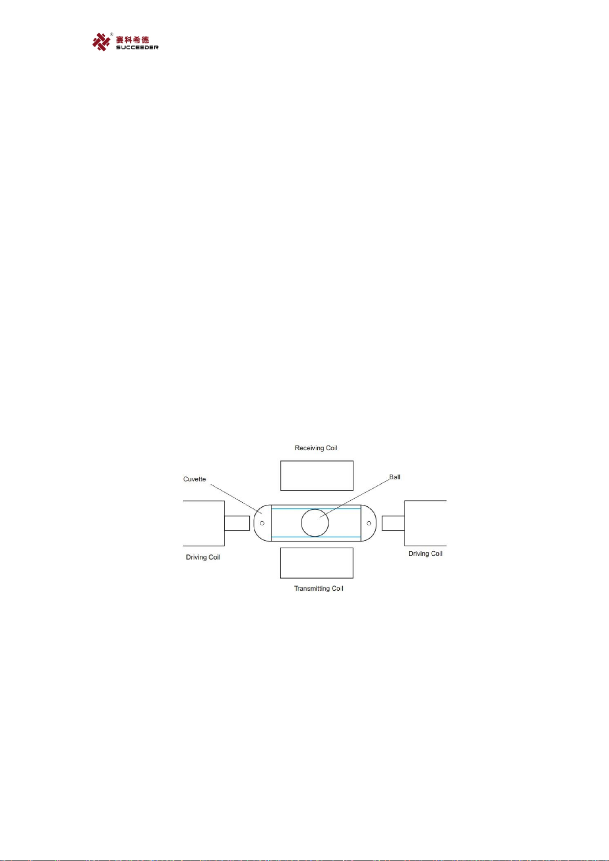
5.3. Principle of clotting method
The detection system for clotting-time assays on the SF-8100 instrument is based on the
increase of viscosity of the plasma being tested. This increase of viscosity is measured through the
motion of a stainless steel ball that is made to affect pendular swings on the two graphd rail tracks
provided in the bottom of the cuvette containing the test plasma.
Constant pendular swings of the ball are created by an electromagnetic field that is applied
alternately on opposite sides of the cuvette by two independent coils. The energy of the
electromagnetic field can be varied depending on the test being performed (weak clot for
Fibrinogen, normal clot for all the others).
Physical Principle of Measurement System
At constant plasma viscosity, ball motion remains constant.
However, as soon as the plasma starts to clot (as a result of the coagulation process being
initiated by the addition of the clot starting reagent), the viscosity of the plasma starts to increase,
and this change in plasma viscosity affects ball movement, slowing it down.As the viscosity
increases, the oscillation amplitude of the ball swing decreases. An algorithm uses these variations
in oscillation amplitude to determine the clotting time.

12
Ball Motion Schema
5.4. Chromogenic substrate method
Enzymes are proteins that catalyze most of the chemical reactions that take place in the
body. They make it possible for chemical reactions to occur at neutral pH and body
temperature. The chemical compound upon which the enzyme exerts its catalytic activity
is called a substrate. Proteolytic enzymes act on their natural substrates, proteins and
peptides by hydrolyzing one or more peptide bond(s).This process is usually highly
specific in the sense that only peptide bonds adjacent to certain amino acids are cleaved.
Chromogenic substrates are peptides that react with proteolytic enzymes under the
formation of color. They are made synthetically and are designed to possess a selectivity
similar to that of the natural substrate for the enzyme. Attached to the peptide part of the
chromogenic substrate is a chemical group which when released after the enzyme
cleavage gives rise to color. The color change can be followed spectrophotometrically and
is proportional to the proteolytic activity. The chromogenic substrate technology was
developed in the early 1970s, and has since then become a tool of substantial importance
in basic research. The majority of chromogenic substrate applications are found in various
clinical fields. In particular they have been used to generate fundamental knowledge of the
mechanisms regulating blood coagulation and fibrinolysis.
5.5. Immunoturbidimetric Method
Immunoturbidimetric are chemical tests used to detect or quantify a specific substance, the
analyte, in a blood or body fluid sample, using an immunological reaction. Immunoassays
are highly sensitive and specific.
Their high specificity results from the use of antibodies and purified antigens as reagents.
An antibody is a protein (immunoglobulin) produced by B-lymphocytes (immune cells) in
response to stimulation by an antigen. Immunoassays measure the formation of
antibody-antigen complexes and detect them via an indicator reaction. High sensitivity is
achieved by using an indicator system (e.g., enzyme label) that results in amplification of
the measured product.
Clotting

13
5.6. Procedure Description
The plasma is pipetted by sampling probe then distributed in a cuvette of incubation site.
If the first reagent is needed, the sampling probe will pipette the first reagent to the cuvette
of incubation site. When reaching incubation time, cuvette-hooking system startup,
hooking the cuvette of incubation site to test site. At the same time, reagent probe pipettes
reagent to the cuvette of test site, then test starts. When test finished, cuvette-hooking
system will hook the cuvette from test site and throws it into the waste bin.

14
6. Installation instruction
6.1. Appearance;
6.1.1. External structure.
External structure;
1. Left cover
2. Switch & ports
3. Upper cover
4. Swiping area
5. Sample racks
6. Right cover
7. Waste box
6.1.2. Connectors & Rinse button
3. Upper cover
4. Swiping area
5. Sample racks
1. Left cover
2. Switch & ports
6. Right cover
8. Connectors
7. Waste box
9. Rinse button

15
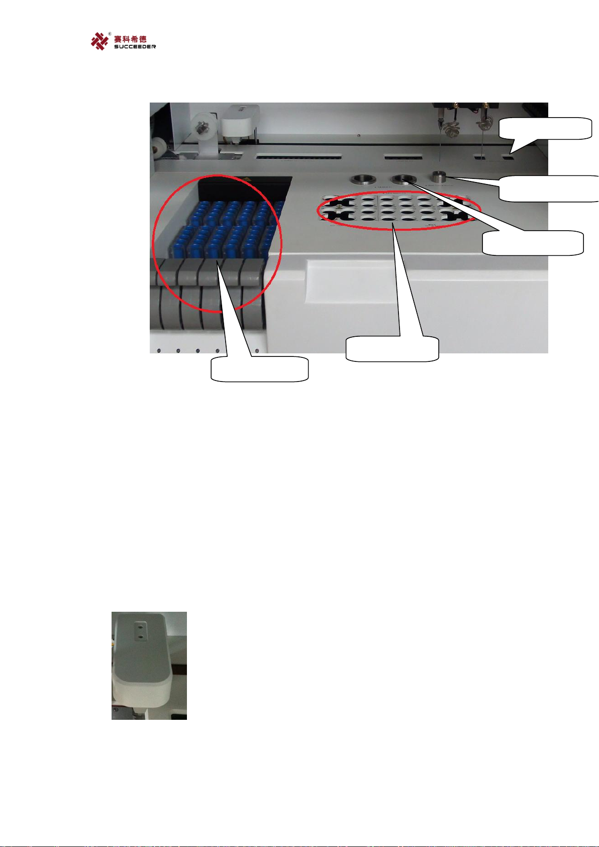
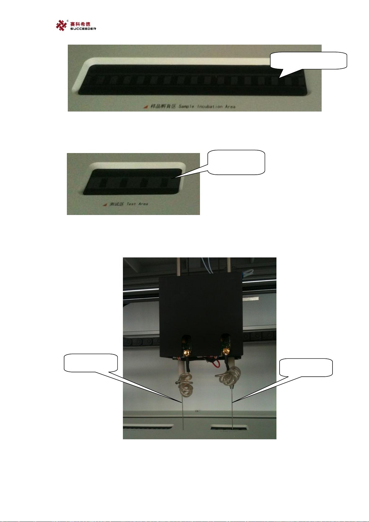
6.1.3. Working Space;
Working space
1. Manipulator
2. Sample incubation area
3. Test area
4. Sample probe
5. Reagent
probe
Power connector
Power switch
Network port
USB port
Sensor connector of
cleaning water box
Tube connector of
cleaning water
Sensor connector of
waste liquid box
Tube connector of
waste liquid
16
1. Manipulator.
2. Sample incubation area.
3. Test area.
4. Sample probe.
5. Reagent probe.
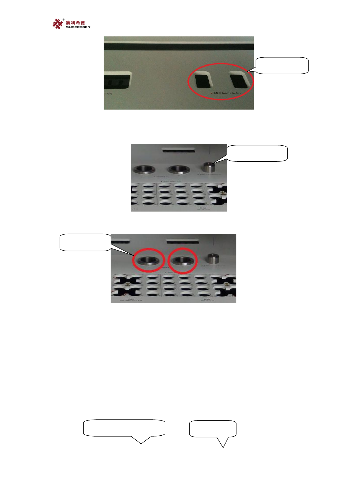
6. Cuvette outfall.
7. Cleaning position.
8. SFT position x2.
9. Reagent area.
10. Sample area.
11. Sample area
6.2. Parts Description:
a. Manipulator.
The part is designed for catch the cuvette to specified position of incubation area.
b. Sample incubation area.
The position is designed for warm up the sample forward to 37℃, it contained with 16
6. Cuvette
outfall
8. SFT position x2
7. Cleaning position
9. Reagent area
10. Sample area
17
positions.
c. Test area.
It is designed for testing with methods of magnetic and optics. It contained with 4 positions
that can be test separately.
d. Sample probe &Reagent probe.
Two probes are designed for suck sample and reagent. The left one is sample probe, the right
one is reagent probe.
e. Cuvette outfall
It is designed for abandon the used cuvette into waste box. It contained with two positions.
16. Incubation
positions.
4 test positions.
Sample probe
Reagent probe
18
f. Cleaning position.
It is designed for clean both probes with cleaning liquid.
g. SFT position x2.
The two SFT positions are designed for clean probes with special cleaning fluid.
h. Reagent area.
The area is designed for placing reagent. It consists of 36 positions that separated by room
temperature area and cooling area, left part for keep reagent in room. temperature, right part
for keep reagent with 16℃.
Cleaning position
SFT position x2
Room temperature area
Cooling area
Cuvette outfall

19
i. Sample area.
It consists of six racks which contained 60 sample positions.
6.3. Cuvette supply system;
6.3.1. Structure of Cuvette supply system;
Cuvette supply system
1. Roll Locker
2. Cuvette roll
Sample area

20
1. Roll locker
2. Cuvette roll
3. Cuvettes
4. Upper roller
5. Lower roller
6. Locker
7. Tighten roller
6.4. Carry-Handles;
Four carry-handles are located at four lower corners that designed for carry machine easily.
6.5. Work platform requirement;
Minimum Size: 1020x 698 cm
Min load bearing: 90kg
Horizontal requirement: Yes
4. Upper roller
Lower roller
5. Lower roller
7. Tighten roller
6. Locker
3. Cuvettes
Carry-handles
Table of contents
Other Succeeder Measuring Instrument manuals


