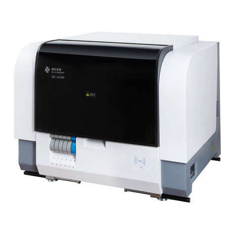
Succeeder SF-8200 User manual

SF-8200 Operation Manual
1/ 76
Thank you for purchasing our product!
Read this manual carefully before using this analyzer!
Specification: SF-8200 Product: Fully Automated Coagulation Analyzer
Beijing Succeeder Technology Inc.
Tower 1A, No. 27 Chuangxin Road, Tec h Park, Changping District, Beijing 102200 China
Te l : +86-10-53855569
Fax: +86-10-53855570
www.succeeder.com.cn
service@succeeder.com.cn
INFORMATION ABOUT AUTHORISED REPRESENTATIVE
NAME: Wellkang Ltd t/a Wellkang Tech Consulting
Te l : +44 (20)30869438, 32876300
Fax: +44(20)76811874
Address: Suite B, 29 Harley Street LONDON W1G 9QR, England, United Kingdom
Please record the following information
User Name:
Laboratory Name:
Analyzer No.: Operator:

SF-8200 Operation Manual
2/ 76
Contents
QUALITY COMMITMENT .........................................................................................................................5
PRECAUTIONS ........................................................................................................................................6
1 GENERAL PRECAUTIONS ............................................................................................................6
2 NOTES ON THE USE OF BIOLOGICAL PRODUCTS ...................................................................6
3 NOTES ON THE USE OF THE INSTRUMENT ..............................................................................6
4 NOTES FOR PREPARING THE TEST ...........................................................................................7
4.1 SAMPLE PREPARATION .....................................................................................................7
4.2 PREPARATION OF REAGENTS ..........................................................................................8
4.3 PROJECT SETTINGS AND INSTRUMENT STATUS...........................................................8
I SF-8200 SIMPLE INTRODUCTION........................................................................................................9
1 OVERVIEW.....................................................................................................................................9
2 INSTALLATION...............................................................................................................................9
2.1 INSTALLATION STATEMENT...............................................................................................9
2.2 INSTALLATION ENVIRONMENT .........................................................................................9
2.3 WORKING ENVIRONMENT...............................................................................................10
2.4 PERIPHERALS...................................................................................................................10
3 INSTRUMENT SPECIFICATIONS ............................................................................................. 11
3.1 INSTRUMENT COMPOSITION.......................................................................................... 11
3.2 Specifications...................................................................................................................... 14
4. ANALYSIS PRINCIPLE................................................................................................................16
4.1 SOLIDIFICATION TEST SYSTEM DESCRIPTION ............................................................ 16
4.2 OPTICAL METHOD TEST SYSTEM DESCRIPTION ......................................................... 16
4.3 TEST PROCESS INTRODUCTION.................................................................................... 17
II ROUTINE USE .................................................................................................................................... 18
1 START THE INSTRUMENT BEFORE CHECKING ......................................................................18
1.1 GARBAGE BASKET INSPECTION ....................................................................................18
1.2 DRAINAGE INSPECTION ..................................................................................................19
2 START THE INSTRUMENT..........................................................................................................21
2.1 TURN ON ...........................................................................................................................21
2.2 LOGIN SAFETY PRECAUTIONS.......................................................................................21
2.3 SOFTWARE INTERFACE DESCRIPTION .........................................................................21
2.4 FUNCTION PANEL.............................................................................................................22
3 REAGENT PREPARATION ..........................................................................................................23
3.1 PREPARE REAGENTS ......................................................................................................23
3.2 REAGENT LOADING / UNLOADING ................................................................................. 24
4 CHECK THE CALIBRATION CURVE ...........................................................................................25
5 QUALITY CONTROL TEST ..........................................................................................................26
6 SAMPLE PREPARATION .............................................................................................................28
6.1 PREPARE THE PLASMA ...................................................................................................28
6.2 PASTE THE BAR CODE .................................................................................................... 28
6.3 SAMPLE LOADING / UNLOADING.................................................................................... 29
III SAMPLE MANAGEMENT...................................................................................................................31

SF-8200 Operation Manual
3/ 76
1. SAMPLE LOADING .....................................................................................................................31
1.1 SAMPLE INTERFACE ........................................................................................................31
1.2 SAMPLE LOADING ............................................................................................................32
1.3 EMERGENCY SAMPLES...................................................................................................34
2 TEST ANALYSIS........................................................................................................................... 35
2.1 "TEST" INTERFACE ........................................................................................................... 35
2.2 TEST TASKS ......................................................................................................................35
2.3 CHECK THE TEST STATUS ..............................................................................................36
3 TEST RESULTS ........................................................................................................................... 38
3.1 SAMPLE SEARCH .............................................................................................................38
3.2 VIEW SAMPLE RESULTS..................................................................................................39
3.3 SAMPLE RESULT REVIEW ...............................................................................................40
3.4 DELETE THE SAMPLE ......................................................................................................40
3.5 PRINT SAMPLE RESULTS ................................................................................................41
ⅣREAGENT MANAGEMENT............................................................................................................... 43
1 BATCH MANAGEMENT ............................................................................................................... 43
2 ENTER REAGENT INFORMATION MANUALLY..........................................................................43
3 SUPPLIES RECHARGE ...............................................................................................................44
4 QUALITY CONTROL PARAMETERS ENTRY.............................................................................. 45
5 REAGENT LOADING ................................................................................................................... 45
5.1 AUTOMATICALLY SAVE AND LOAD REAGENT LAYOUTS..............................................45
5.2 REAGENT LOADING/UNLOAING......................................................................................46
ⅤQUALITY CONTROL.........................................................................................................................47
1 QC SETTING................................................................................................................................47
2 QC TEST ...................................................................................................................................... 48
3 INQUIRE THE QUALITY CONTROL RECORD............................................................................ 48
ⅥCALIBRATION ................................................................................................................................... 50
1 CHECK THE CALIBRATION CURVE ...........................................................................................50
2 CREATE A CALIBRATION CURVE...............................................................................................50
2.1 SET THE CURVE PARAMETERS......................................................................................50
2.2 LOAD CALIBRATORS AND REAGENTS ........................................................................... 51
2.3 CREATE A CALIBRATION CURVE .................................................................................... 52
3 MODIFY THE CURVE ..................................................................................................................54
4 DELETE THE CURVE ..................................................................................................................54
ⅦINSTRUMENT SETTING...................................................................................................................55
1 GENERAL SETTING .................................................................................................................... 55
1.1 REPORT SETTING ............................................................................................................55
1.2 USER SETTING .................................................................................................................55
1.3 LANGUAGE SETTING ....................................................................................................... 56
1.4 LIS SETTING...................................................................................................................... 57
1.5 REPORT RANGE SETTING............................................................................................... 57
1.6 DATA BACKUP ...................................................................................................................57
2 TEST ITEM SETTING................................................................................................................... 58
2.1 TEST INFORMATION ......................................................................................................... 58

SF-8200 Operation Manual
4/ 76
2.2 TEST ITEM PROCEDURE SETTING................................................................................. 59
2.3 TEST PARAMETERS AND DILUTION FUNCTION SETTING ...........................................61
2.4 RESULT UNIT SETTING ....................................................................................................63
2.5 ADD OTHER ITEMS........................................................................................................... 64
3 DICTIONARY SETTINGS ............................................................................................................. 65
4 EQUIPMENT ADVANCED FEATURES OPTIONS .......................................................................66
4.1 CHANNEL SETTING ..........................................................................................................66
4.2 REAGENT AREA POSITION CHECKING ..........................................................................66
4.3 SETTINGS FRO DIPOSE THE CUVETTE WHICH LACK REAGENT ............................... 66
4.4 SETTINGS FOR CALCULATE THE MEAN VALUE AUTOMATICALLY..............................66
5 SYSTEM INFORMATION ............................................................................................................. 67
5.1 INSTRUMENT INFORMATION...........................................................................................67
6 LOG ..............................................................................................................................................68
ⅧMAINTENANCE ................................................................................................................................69
1 MAINTENANCE SCHEDULE ....................................................................................................... 69
2 DAILY MAINTENANCE.................................................................................................................69
2.1 MAINTAIN INTERFACE...................................................................................................... 69
2.2 DAILY MAINTENANCE....................................................................................................... 70
3 MONTHLY MAINTENANCE.......................................................................................................... 70
4 HALF YEAR MAINTENANCE ....................................................................................................... 73
5 SPARE PARTS RECHARGE ........................................................................................................ 73
ⅨFAQ ................................................................................................................................................... 75
1 FAQ SOLVING.............................................................................................................................. 75

SF-8200 Operation Manual
5/ 76
QUALITY COMMITMENT
The company's manufactured products undergo a rigorous quality inspection, would be in full com-
pliance with the technical requirements of this product
The analyzers pass the safety testing and performance testing of medical device testing agencies,
they would be in line with national standards and industry standards
The product is manufactured under the quality system conforming to ISO13485 and ISO9001. The
quality system of our company is certified by TUV
The device complies with the emission and immunity requirements of GB / T18268.1-2010 and GB /
T18268.26-2010
This equipment is designed and tested according to Class A of GB4824. This equipment may cause
radio interference in home environment and need protective measures
It is recommended to evaluate the electromagnetic environment before using this equipment
Do not use the device near strong radiation sources (such as unshielded RF sources), otherwise it
may interfere with the normal operation of the device
The company product’ design life is 5 years, one year warranty and lifetime maintenance.

SF-8200 Operation Manual
6/ 76
PRECAUTIONS
1 GENERAL PRECAUTIONS
Before installing and using the instrument for the first time, please read the instructions in the
manual carefully and strictly observe the operating procedures and precautions. The instrument must be
operated in accordance with the methods specified in this manual. Failure to use the device in accord-
ance with the methods specified in this manual may damage the protection provided by the device.
Before reading the manual, make sure you understand the following logo. Please refer to "Chapter 1 3.1
Instrument Composition."
Attention
Be careful of burns
Laser radiation
Biohazard
Protect the ground
Any failure to observe the above marks and operate the instrument incorrectly may result in injury to
the operator, adverse effects on output, and potential hazards of property damage.
This product is a clinical testing instrument, Based on the analysis results, the doctor is required to
consider the clinical test results and other test results at the same time.
2 NOTES ON THE USE OF BIOLOGICAL PRODUCTS
For all biological products (reagents, calibrators, quality control plasma and patient plasma, etc.),
please read the precautions regarding potential contamination carefully.
1) Do not eat or smoke in areas where biological products are used;
2) Do not use expired reagents;
3) Reagents are chemicals used for in vitro diagnosis and can not be used as medicines.
4) When using biological products, please wear disposable rubber gloves, if the biological products come
into contact with your skin wounds or mucous membranes, rinse immediately with water and see a doc-
tor;
5) Dispose of all used biological waste products according to local laws or regulations (eg. heat steriliza-
tion, discard, waste water treatment with sodium hypochlorite, etc.).
3 NOTES ON THE USE OF THE INSTRUMENT
1) The instrument has protective measures in the transport package. It must be installed by a profes-
sional engineer trained by our company or authorized engineer of our company.
2) All the warning signs, the operator must check the instructions in the relevant content, identifying po-
tential hazards;

SF-8200 Operation Manual
7/ 76
3) The network power must have a protective earth terminal. Internal protective grounding terminal
marked with symbols, must be reliably grounded through the power outlet.
4) The network power input socket is a disconnect device for the power supply of the instrument and the
network. Do not install this device in a hard-to-disconnect position.
5) In the possible damp places, should be installed leakage protector.
6) For safety, do not open the front cover of the instrument or insert your fingers into the instrument dur-
ing testing, which may result in personal injury. If the front cover is opened during the test, the instrument
will sound the alarm and stop working at the same time. When closing the front cover, hold the front cover
with your hands and slowly lower it. During the test, the operation table inside the instrument prohibits
placing extra items.
7) Unless instructed in this manual, do not attempt to open it yourself. It may cause high voltage or other
hazards to you. Maintenance of these parts should be done by qualified personnel.
8) When inspecting or maintaining, please use protective rubber gloves or other protective measures,
and use specific tools or parts. After finishing the work, please wash your hands with disinfectant.
9) The company's instruments are equipped with a power regulator, generally do not need an external
voltage regulator. Only when the external power supply voltage fluctuations exceed 100-240V, you can
use the UPS regulator, you cannot use the ordinary regulator.
4 NOTES FOR PREPARING THE TEST
4.1 SAMPLE PREPARATION
1) Selection and dosage of anticoagulants
Anticoagulant 105-109mmol / L, 3.13% -3.2% (usually described as 3.2%) of sodium citrate
(Na3C6H5O7 • 2H2O), other anticoagulants such as heparin, EDTA, oxalate, etc. are not allowed to use.
The final concentration when anticoagulant is mixed with blood is usually 10.9-12.9 mmol / L. Anticoag-
ulant and blood volume ratio of 1: 9.
If the patient's hematocrit (HCT) greater than 55% or less than 20%, usually need to adjust the
amount of anticoagulant.
The amount of anticoagulant can be adjusted according to the following formula:
X = required anticoagulant amount × [(100 - HCT) / (595 - HCT)]
Of which: x - ml, the amount of anticoagulant required
HCT -%, hematocrit
Such as: need 5ml anticoagulant, the patient's HCT = 20%, the required anticoagulant x = 0.7ml
2) Sample collection
Equipment in contact with blood, such as test tubes, pipettes, and syringes must be plastic.
Acquisition should be fasting state in the morning, take the elbow venous blood, the sample size can not
be less than 2 ml. Blood should be sharp, avoid repeated puncture, to avoid hemolysis, platelet aggre-
gation, pumping tissue fluid or bubbles mixed phenomenon, such as hemolysis should be re-drawn
blood.
Bleeding blood and anticoagulants, the method should be gentle, not violent shaking. The antico-
agulant mixture was centrifuged at a temperature of 25-32 ° C, the relative centrifugal force of plasma
separation was 1500 × g, and the centrifugation time was controlled at about 15 minutes until the cen-
trifuge was stopped naturally (for example, hemolysis should be reabsorbed ), Test tube supernatant

SF-8200 Operation Manual
8/ 76
liquid is platelet poor plasma (PPP).
3) Sample placement
Coagulation Test The PT test sample should be tested within 24 hours at (18-24) °C; the APTT test
sample should be tested within 4 hours; other tests (eg FIB, PC, Factor V, Foctor VIII, D-Dimer, FDP, etc. )
Should be tested within 4 hours.
If the clotting test cannot be performed immediately, the sample can be stored at 4 °C for 2 hours. If
the PT test sample cannot be tested within 24 hours or the APTT and other tests cannot be tested within
4 hours, the plasma sample can be stored frozen below-20 °C for two weeks and below -70 °C for 6
months. Frozen samples should be rapidly thawed at 37 °C and tested immediately. Frozen samples may
affect the APTT test.
4.2 PREPARATION OF REAGENTS
1) Use of reagents
Users in the reagent before use, be sure to read the instructions inside the kit, and strictly in ac-
cordance with the provisions of the manual to use and save.
Test reagent configuration and dosage can refer to the user to use the reagent packaging and in-
structions, reagents should choose a legal solidification method, the optical method of reagent determi-
nation of the box, the use of different batches and manufacturers of reagents need to do calibration,
coagulation test for calibration Calibrators must be used, different batches, different components cannot
be mixed.
2) PT reagent selection
Select a reagent labeled ISI (International Sensitive Index) for quality control. The lower the ISI
value of the reagent, the more sensitive it is to each coagulation factor measured.
4.3 PROJECT SETTINGS AND INSTRUMENT STATUS
1) Project Settings
Experimental settings must be provided by the manufacturer of reagents set, such as temperature
incubation time, test time, and sample, reagent, buffer, the amount of cleaning fluid.
2) Needle and pipeline maintenance
The purpose of the needle maintenance is to clean the outer surface of the needle to avoid
cross-contamination affect the test results. The purpose of pipeline perfusion maintenance is to make the
pipe filling part of the filling system full of cleaning liquid to reduce the wall bubble, to avoid the amount of
sample is not allowed to affect the test results.
Every morning before the start of the test need to carry out the needle and the pipeline maintenance,
in the course of one day of use, half an hour to suspend the use of the instrument, please use pipeline
maintenance before use.

SF-8200 Operation Manual
9/ 76
I SF-8200 SIMPLE INTRODUCTION
1 OVERVIEW
SF-8200 fully automated coagulation analyzer for coagulation and anticoagulation of human
plasma, fibrinolysis and anti-fibrinolytic function of the test, to quickly and accurately analyze a large
number of samples.
This instrument is for in vitro diagnosis only.
Figure 1.1 SF-8200 Fully automated coagulation analyzer
2 INSTALLATION
2.1 INSTALLATION STATEMENT
The SF-8200 Automated Blood Coagulation Tester has been thoroughly inspected at the factory
and carefully packed to prevent damage due to vibration during shipping.
After delivery, please double-check the packaging to confirm that the instrument is free from any ex-
ternal damage.
SF-8200 automated coagulation analyzer can only be Beijing Succeeder Technology Inc. profes-
sional engineers or by the Company authorized engineers to install at the same time the initial set.
After the instrument is installed and running, it should not be moved normally. If you really need to move,
you should empty the pipes and trash basket waste, and fixed XYZ sampling arm mechanism, robot
movement mechanism and trash basket. There is a groove on each side of the bottom of the instrument.
When transporting, put your hand here and raise it horizontally.
2.2 INSTALLATION ENVIRONMENT
1) Choose a stable level surface to avoid functional errors when installing.
2) Make sure the installation space is large enough for operation and maintenance. Place the computer
on the left side, wash tub and waste tub on the right side, and make sure that the bin on the right side is
completely removable.
3) The network power must have a protective earth terminal. Internal protective grounding terminal
marked with symbols, must be reliably grounded through the power outlet.

SF-8200 Operation Manual
10 / 76
4) The network power input socket is a disconnect device for the power supply of the instrument and the
network. Do not install this device in a hard-to-disconnect position.
5) The analyzer contains non-corrosive gases, non-toxic gases, no special ventilation requirements.
Figure 1.2 Instrument Installation Environment
2.3 WORKING ENVIRONMENT
1) Installation category: II (overvoltage category)
2) Class of pollution: II
3) Voltage: AC100-240V(50Hz)
4) Temperature: 15℃~30℃(23℃best)
5) Relative humidity: Not exceed 75%(30% - 75% best)
6) Barometric pressure: 86.0kPa~106.0kPa
7) Operation system: Win98/ME/WINNT4/WIN2000/WINXP/WIN7/WIN10
8) Avoid direct heat and light exposure
WARNING: Make sure the instrument is grounded. Improper grounding may cause electric
shock.
2.4 PERIPHERALS
1) The computer system is not less than the following configuration:
CPU: frequency 1GHZ above, 32-bit or 64-bit processor;
Display: VGA color display, supports 1024 × 768 resolution and above;
Hard disk: at least 16 GB of free space (based on 32 bits) or 20 GB of free space (based on
64 bits)
Memory: The minimum requirement is at least 1G, more than 2G recommended;
Graphics Card: DirectX 9 graphics device with WDDM 1.0 or later driver;
Operating System: Correct preinstalled Win98 / ME / WINNT4 / WIN2000 / WINXP / WIN7 /
WIN10 operating system;
Printer: support for the operating system and motherboard
2) External socket
①USB (IC card)
②RJ45
③Power cord

SF-8200 Operation Manual
11 / 76
④Alarm for waste solution
⑤Alarm for cleaning solution
⑥Inflow socket
⑦Outflow socket
3 INSTRUMENT SPECIFICATIONS
3.1 INSTRUMENT COMPOSITION
3.1.1. Instrument appearance
Left side view of the instrument
1) Communication interface
USB interface: IC card reader connection port, connected with the PC;
RJ45 network port: instrument communication port, connected with the PC;
2) left maintenance window
Used to check the positioning of manipulator grasping maintenance window, the need to open the tool;
3) Fuse box window
To facilitate the replacement of the instrument's internal circuit board fuse set maintenance window, the
need to open the tool;
4) Power switch and interface
Use the power cord provided by the manufacturer to power the instrument;
|: Turn on the power;
○: Turn off the power;
WARNING: TO PREVENT ELECTRICAL SHOCK, CONNECT THE POWER CORD
WITH POWER OFF.
5) Left front door
Can be opened, used to replace the test cuvette and plate, the specific operation refer to "Chapter II 1.3
Test Cuvette Check";
6) IC card swipe area
For consumables recharge and reagent information entry, the specific operation refer to "Chapter VII 1.2
consumables recharge";
7) front cover
The front cover of the instrument has the function of opening and closing the cover to stop the
machine and the instrument can work normally only when the front cover is closed. At the same time,
closing the bezel minimizes ambient light interference to ensure a good optical test environment.

SF-8200 Operation Manual
12 / 76
56 87
WARNING: Do not open the front cover during
instrument testing as this may cause the
instrument to stop operating or produce incorrect test results.
8) reagent barcode scanning window
For reagent automatic scanning code loading, the specific operation refer to "Chapter II 3.2 rea-
gent loading / unloading";
Attention! Bar code scanner is on, the brightness is higher, do not look directly at the light
beam.
9) In/outflow port
Waste liquid connection interface: with liquid waste alarm indicator light, full liquid switch to con-
nect the faucet and alarm connector;
Cleaning liquid connection interface: lack of liquid cleaning liquid alarm indicator, the lack of liquid switch
to connect the tap and alarm connector;
10) Garbage basket
Test cuvettes after use will be discarded in trash baskets, please use trash bags, and clear the
trash baskets in time.
WARNING: Rubbish baskets contain potentially biodegradable materials. Wear rubber
gloves for disposal and disposal in accordance with local regulations.

SF-8200 Operation Manual
13 / 76
3.1.2. Internal components of the instrument
1) manipulator
Used to test the handling of the cuvette, with rotation, can avoid the needles, improve operating
efficiency.
2) Reagent arm
Independent loading arm, used to start the reagent loading, running the reagent zone for the rea-
gent zone start reagent zone and the test position;
Reagent needle has a heating function, draw reagent, the reagent warmed up quickly to meet the
test requirements;
WARNING: Beware of possible heat burns on the surface of the
reagent needle. Use
caution.
3) Sample arm
Independent loading arm, for sample and intermediate reagent loading, the operating area for the
reagent reagent in the middle of the reagent zone and temperature;
4) temperature position
20 holes temperature, temperature control and design of insulation to ensure good wet and cold
areas, the effect of temperature.
Warning: Beware of possible high temperature on the surface of the incubation temper-
ature.
5) sample bit
Six pull-out tube rack, each tube rack has 10 sample holes, a total of 60 sample positions.
Built-in sample barcode scanner, you can automatically determine the sample rack into and out, only

SF-8200 Operation Manual
14 / 76
push the bar code scanning, and prompted to load the sample information in the software.
Warning: The sample has potential biochemical hazards, please wear rubber gloves
operation.
Warning: laser radiation, do not look directly at the light beam.
6) Reagent positions
Intermediate reagent area: 24 holes, can place 1 bottle of 25ml specifications reagent, 3 bottles of
15ml specifications reagent, 10 bottles of 5ml specifications reagent, 10 bottles of 2ml specifications
reagent, which contains two reagent stirring position, located in the middle reagent position
Start the reagent area: 18 holes, can place 3 bottles of 25ml specifications reagents, 15 bottles of
5ml specifications reagent, which contains three reagents stirring position, left in the start reagent posi-
tion three holes.
2 sets of independent cleaning tank, respectively, cleaning the sample needle and reagent needle.
With condensate collection and discharge function, to improve the reagent position in high temperature
and humidity environment stability.
7) test positions
Solidification test positions: 4
Optical method test positions: 4
Test zone heating function, for the sample during the test to maintain a constant temperature.
Warning: Beware of possible high temperatures on the surface of the test site. Use cau-
tion.
3.2 Specifications
1) temperature control
When the room temperature is 15℃~ 30℃, the temperature control in the following range:
Temperature and test position temperature control bit 37.0℃± 1.0℃;
Reagent temperature control does not exceed 16℃;
The preset temperature is reached within 30 minutes after the power is turned on.
2) test items and reporting units
Using the clotting method, chromogenic substrate method, immunoturbidimetric method for the
following coagulation tests and scalable items
Items
Clotting method
(Mechanical method)
Optical method
Reportable unit
chromogenic sub-
strate method
immunoturbidimetric
method
PT ※s, INR, %, R
APTT ※s

SF-8200 Operation Manual
15 / 76
TT ※s
APC-R ※s
FIB ※s, g/l, mg/dl
PC
※s, %
※%, OD/min
PS
※s, %
※%, OD/min
PLG ※%, OD/min
PAI ※%, OD/min
D-Dimer ※DOD, μg/ml
FDP ※DOD, μg/ml
FM ※DOD, μg/ml
vWF ※※%, DOD, s
TAFI ※%, DOD
Free-Ps ※%, DOD
AP ※%, OD/min
E Factor ※※s, %
I Factor ※※s, %
HNF/UFH
※IU/ml, s
※IU/ml, OD/min
LMWH ※※IU/ml, OD/min
AT-Ⅲ
※s, %
※%, OD/min
3) sample volume range
5 μl - 250 μl
4) carrying pollution rate
FIB high concentrations of low concentrations of carrier pollution should be ≤ 10%
FIB or TT on PT or APTT carrier contamination rate ≤ 2%
PT or APTT on AT-Ⅲcarrier pollution rate ≤ 2%
The carrying rate of D-Dimer by PT or APTT is less than 2%
5) Repeatability
Item(Unit)
CV
Normal Sample Abnormal Sample
Clotting method(Mechanical method)
PT(s)≤3.0% ≤5.0%
APTT(s)≤3.0% ≤5.0%
FIB(g/L)≤5.0% ≤10.0%
TT(s)≤3.0% ≤5.0%

SF-8200 Operation Manual
16 / 76
Optical
method
chromogenic sub-
strate method
AT-Ⅲ(%)≤5.0% ≤10.0%
immunoturbidimetric
method
D-Dimer(μg/ml)≤10.0% ≤5.0%
Note:
1, the conventional four abnormal samples refers to not less than twice the median value of the normal reference range
of the instrument;
2, AT-Ⅲnormal sample concentration of 80% -120%, abnormal sample concentration of 30% -79% and 120% -140%;
3, D-Dimer normal sample content (0.15-0.5) μg / ml, abnormal sample concentration (0.5-8) μg / ml
6) Accuracy
The relative bias measured by the FIB does not exceed ± 10.0%.
AT-Ⅲmeasurement results should be consistent with the quality control of the target range.
D-Dimer measurement results should be consistent with the control target range.
7) Linearity
The linearity range of FIB was determined to be 0.7-7 g / L, r ≥ 0.975.
The linearity range of AT-III was determined: 9% -140%, r> 0.98.
The linearity range of D-Dimer was determined to be 0.15-8 ug / ml, r> 0.98.
4. ANALYSIS PRINCIPLE
4.1 SOLIDIFICATION TEST SYSTEM DESCRIPTION
The test is based on the increasing viscosity of the plasma being tested, and an increase in the
viscosity of the plasma is detected by the curved movement of the test bead at the base of the cuvette.
Independent coils on both sides of the cuvette generate opposite electromagnetic fields that drive the
test bead. The viscosity does not change when the plasma does not coagulate, and the test beads will
swing with a constant amplitude; When the plasma is coagulated, fibrous protein occurs, plasma vis-
cosity will be increased, and the amplitude of test bead will be attenuated. The change of amplitude is
calculated by mathematical algorithm and then get the clotting time.
4.2 OPTICAL METHOD TEST SYSTEM DESCRIPTION
There are two methods of optical method: chromogenic substrate method, immune turbidimetry.
Chromogenic substrate method: artificial synthesis of a cleavage site compounds and chromogenic
substances linked to form a specific substrate for the enzyme, due to the presence or reaction of the
sample was generated during the activity of the enzyme, the substrate was Hydrolysis and release of
chromogenic substances, the reaction system of color change, colorimetric method to detect the extent
of its color change, and the enzyme activity or analyte into a certain relationship.
Immunoturbidimetric method: the use of antigen and antibody specificity between the characteris-

SF-8200 Operation Manual
17 / 76
tics of the test substance and labeled with its specific antibody particles, making the reaction system of
turbidity change, by measuring the change in light intensity to be Method of measuring objects.
Optical method detection principle: After a monochromatic light through the reaction vessel, part of
the incident light is absorbed or refracted by the reaction medium, the transmitted light is detected by the
detection system, and through the formula converted into absorbance (optical density, O. D.).
4.3 TEST PROCESS INTRODUCTION
Test process diagram:
测试位37℃恒温育温位37℃育温
血浆 启动试剂
样本针
测试杯
中间试剂
试剂针
测试杯
机械手运送 即时测试
结果计算
清洗 清洗
The sample needle aspirates a quantitative amount of plasma and adds to the test cuvette at the
incubation temperature. According to the project requirements, if you need to add intermediate reagent,
the sample needle to absorb the corresponding reagent added to the test cuvette co-incubation tem-
perature. The sample needle will be properly cleaned after each pipetting step. When the incubation
time is reached, the robotic arm moves the test cuvette from the incubation temperature to the test
position. At this point, the reagent needle aspirates the starter reagent into the test cuvette of the test
position and begins the test at the same time. Similarly, reagent needles are cleaned after each pipet-
ting step. When the test is completed, the robotic arm system drops the test cuvette into the trash bas-
ket.
5. Storage conditions
The packaged tester should generally be stored in an ambient temperature of -20 ℃~ 55 ℃, rela-
tive humidity less than 85%, non-corrosive gases and well-ventilated room.
Contraindications
Not yet found
plasma
test
cleanclean
Intermediate
Reagent
Activation
Reagent
plasma
37
℃
incubation
cuvette
37
℃
incubation
cuvette results
Sample needle
reagent needle
transfer

SF-8200 Operation Manual
18 / 76
II ROUTINE USE
1 START THE INSTRUMENT BEFORE CHECKING
1.1 GARBAGE BASKET INSPECTION
垃圾袋
垃圾筐
Pull out the instrument trash basket, remove the distance of about 260mm, remove the trash bag,
dispose of bio-waste according to local regulations;
The new garbage bag into the rubbish box, the garbage basket pushed back to the instrument;
Note! Please reserve enough space on the right side of the instrument to facilitate the re-
moval of rubbish baskets.
Instrument has a "garbage basket in place detection" function, if not placed in place, the instrument may
not work and alarm
WARNING: Rubbish baskets contain potentially biodegradable materials. Wear rubber
gloves for disposal and disposal in accordance with local regulations.
Plastic bag
Waste basket

SF-8200 Operation Manual
19 / 76
1.2 DRAINAGE INSPECTION
废液满液报警接口
及排水水嘴接头
清洗液缺液报警接口
及进水水嘴接头
Alarm interface with quick connector, insert, you need to limit the connector and the interface of the
instrument alignment;
When the water inlet and exhaust nozzles are equipped with quick-closing faucets, press the reed
of the water faucets, the water faucets will pop up automatically when the faucet is clicked; if it cannot be
inserted, please check the spring Whether the film is pressed in place.
Note! Drainage faucet if not in place, will cause drainage blockage, cannot be discharged in
time, leading to overflow within the instrument.
Check the cleaning liquid tank. If the liquid level of the cleaning liquid is low, replace the liquid
cleaning liquid. The liquid cleaning liquid cannot be replaced by other liquid, and dispose of the waste
liquid tank at the same time.
WARNING: Waste drums contain
potentially biodegradable materials. Wear rubber gloves
and dispose of in accordance with local regulations.
L
iquid-overflow switch
Liquid deficient switch
Waste liquid barrel
Cleaning liquid barrel
Liquid-
overflow alarm and
outflow pipe adapter
Liquid-
outflow alarm and
inflow pipe adapter
Table of contents
Other Succeeder Measuring Instrument manuals
Popular Measuring Instrument manuals by other brands

Martek Instruments
Martek Instruments Mark 25 instruction manual
Bender
Bender ISOMETER isoPV425 with AGH420 Quick Star Guide

Thermo
Thermo DCT7088 user manual

EINHELL
EINHELL 21010 Original operating instructions
Owon
Owon HSA1000 Series user manual

Teledyne Lecroy
Teledyne Lecroy MDA810 Getting started guide
Kingfisher
Kingfisher KI6106 Series user manual
AST
AST A250 PL/TL BT user manual
T&D
T&D RTR-574-S manual
Elenco Electronics
Elenco Electronics TT-400K Assembly and instruction manual

PCB Piezotronics
PCB Piezotronics 351B14 Installation and operating manual
Mirion Technologies
Mirion Technologies LDM 320 user manual

