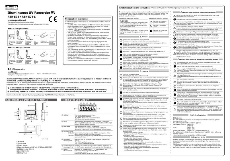
T&D RTR-574-S User manual

Appearance Diagram and Part Names
To prevent any loss or damage to our customers, other people and/or property, and to ensure the
proper use of our products we ask that before using our product you carefully read, understand and
follow the safety rules and precautions for our products as outlined below.
Explanation of Warning Symbols Explanation of Picture Symbols
DANGER
These entries are actions that
absolutely under no circumstance
should be taken. The taking of
such an action may cause serious
personal physical damage or
death.
Denotes an important
warning or caution.
Denotes a forbidden action.
CAUTION
These entries are actions that if
taken may lead to physical injury
or damage to persons or things.
Denotes an action that
must be taken.
DANGER
Do not take apart, repair or modify the Unit.
Touching them may result in malfunction or unexpected accidents.
If water or a foreign object enters into the Unit, immediately turn OFF the power, remove
batteries, and stop using.
Continued use may cause re or electrocution.
Do not use this Unit in wet or humid places, such as a bathroom.
It may cause a re or other trouble including malfunction.
If water or a foreign object enters the case, immediately cease using it.
Store the Unit and accessories out of the reach of children.
Touching them may result in unexpected accidents.
If any smoke or strange smells are emitted from the Unit, immediately turn OFF the power,
remove batteries, and stop using.
Continued use may cause re or electrocution.
Do not drop the Unit, or expose the Unit to a strong impact.
If that happens to the Unit, immediately turn OFF the power, remove batteries, and stop using. Continued use
may cause re or electrocution.
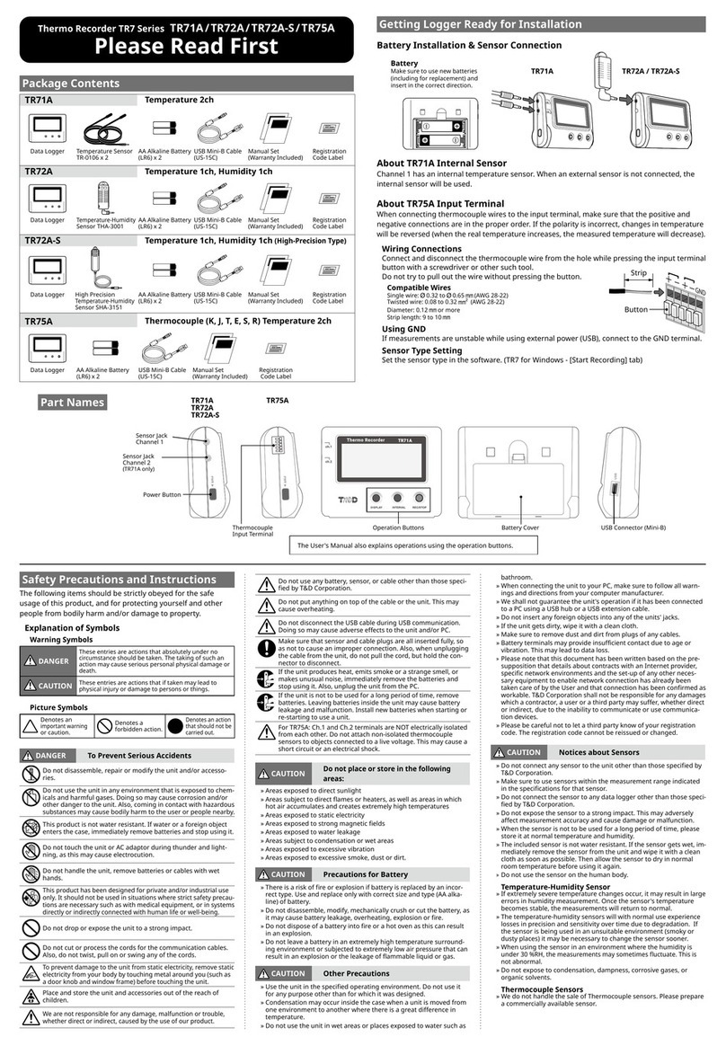
When installing and using this product, make sure to follow all warnings and directions from
your computer manufacturer.
CAUTION
This Unit is not waterproof.
If the Unit gets dirty, wipe it with a clean cloth.
Harmful gases or chemicals may cause corrosion and/or other danger to the Unit. Also, by
coming in contact with hazardous substances, harm may occur to the people handling the
Unit. Therefore, do not use or store the Unit in any environment that is exposed to
chemicals and harmful gases.
Battery life varies depending upon the type of battery, the battery performance, the
measuring environment, and the frequency of communication.
Battery terminals may provide insufcient contact due to age or vibration.
This may lead to data loss.
Use the Unit in an environment within the operational range.
Condensation may occur when a Unit is moved from one environment to another where
there is a great difference in temperature.
To prevent damage to the Unit from static electricity, remove static electricity from your
body by touching metal around you (door knob, window frame) before touching the Unit.
Static electricity may cause not only damage to the Unit, but may cause breaks in or a loss of data.
If the Unit is not to be used for a long period of time, for safety reasons please remove the
battery.
If left in the Unit, it may leak and lead to malfunctioning.Please use a new battery when you use the Unit
again.
Do not store or leave the Unit in any place exposed to high temperature and high humidity.
If the Unit is not to be used for a long period of time, store it in a place with a normal temperature and without
condensation with other items included.
Do not disconnect the communication cable during USB communication.
This may harmfully effect the Unit or your PC.
We shall not guarantee the operation of our device if you have connected it to your
computer using a USB hub or a USB extension cable.
Please do not insert your ngers or any foreign objects into the sensor or USB connection
jacks.
Do not use or store the Unit in any of the following places. Doing so may cause
electrocution, re and/or other adverse effects to the device and/or your computer.
-Areas exposed to direct sunlight
This will cause the inside of the Unit to become overheated and may cause re, deformation, and/or
other damage including malfunction.
-Areas prone to strong magnetic elds
This may cause damage including malfunction.
- Areas exposed to water leakage
This may cause electrocution or other damage including malfunction.
- Areas exposed to excessive vibration
This may cause injury, malfunction, damage or loss of proper electrical contact.
- Areas near re or exposed to excessive heat
This may cause damage including malfunction and deformation.
-Areas prone to dust and dirt
This may cause damage including malfunction.
Illuminance UV Recorder WL RTR-574 is a Data Logger, with built-in wireless communication capability, designed to measure and record
Illuminance, UV Intensity, Temperature and Humidity at a set interval.
Recorded data can be downloaded from an RTR-574 Data Logger (Remote Unit) via wireless communication with a Base Unit; that data can then be viewed in a graph and/or
saved to PC for analysis or sharing over a network.
As a Remote Unit, RTR-574 requires a Base Unit to carry out wireless communication. (Compatible Base Units: RTR-500, RTR-500NW, RTR-500AW,
RTR-500DC, RTR-500MBS-A)
The RTR-574 can be operated with "RTR-500 for Windows" version 1.10 or later.
When you use "RTR-500 for Windows", please check the software version by selecting "Version Info" in the [Help] Menu. The latest version of the
software can be downloaded from our T&D Web Site.
Before using an RTR-574, it is first necessary to install the USB Device Driver from the software that comes with the Base Unit.
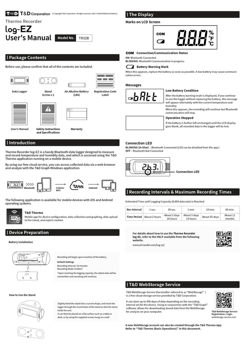
REC Mark The recording status is shown here.
ON: Recording in progress.
BLINKING: Waiting for programmed start.
OFF: Recording has been stopped.
DATA The number of recorded readings is shown in a scale here. After every
2,000 readings the scale is marked from left to right. Storage capacity is
8,000 readings.
COM Mark The communication status is shown here.
ON: The Unit is connected to a PC with the USB cable.
BLINKING: The Unit is in Wireless/USB/Serial communication.
Recording Mode ENDLESS:
Upon reaching storage capacity of 8,000 readings, the oldest data is
overwritten and recording continues.
ONETIME:
Upon reaching storage capacity of 8,000 readings, recording will
automatically stop.
Battery Life
Warning Mark
When it is time for the battery to be replaced, this mark will appear.
Not ON: Ample battery power.
ON: Time to change the battery.
Current Readings /
Messages Area
Normally, the current readings are shown here. Depending on the Unit’s
status, operational messages may also be displayed.
Unit of
Measurement
Humidity: % , Temperature: ˚C / ˚F, Illuminance: lx, klx
Cumulative Illuminance: lxh, klxh, Mlxh
UV Intensity : mW/cm2,
Cumulative Amount of UV Light: mW/cm2h, W/cm2h
Antenna
Sensor Jack
POWER Button
Operation Buttons
(DISPLAY, INTERVAL,
REC/STOP)
USB Communication
Cable Jack
Battery Cover
Notices about this Manual
In order to properly use this product, please carefully read this manual before using. T&D Corporation accepts no responsibility for any malfunction of and / or trouble with this product or with your
computer that is caused by the improper handling of this product and will deem such trouble or malfunction as falling outside the conditions for free repair outlined in the attached warranty.
- All rights of this Manual belong to T&D Corporation. It is prohibited to use, duplicate and / or arrange a part or whole of this Manual without the permission of T&D Corporation.
- "TANDD", "T&D" and the logo of T&D Corporation are all registered property of T&D Corporation.
- Specications, design and other contents outlined in this manual are subject to change without notice.
- We are not responsible for any malfunction or trouble caused by the use of our product or by any problem caused by the use of measurement results of our unit. Please be fully aware of this before using our product.
- On screen messages in this manual may vary slightly from the actual messages.
- Please notify the shop where you purchased this product or T&D Corporation of any mistakes, errors or unclear explanations in this manual.
- T&D Corporation accepts no responsibility for any damage or loss of income caused by the use of our product.
- This product has been designed for private or industrial use only. It is not for use in situations where strict safety precautions are necessary such as in connection with medical equipment, whether directly or indirectly.
- This Manual cannot be reissued, so please keep it in a safe place.
- Please carefully read this Manual and Warranty.
Safety Precautions and Instructions * Please carefully observe the following safety measures when using our product.
18
55
78
60
[Unit : mm]
Cautions about using the Illuminance UV Sensors
Do not connect the ISA-3151 sensor to any data logger other than those specied by T&D
Corporation.
Use the Unit in an environment within the operational range.
When measuring UV light or other light which may cause damage or injury to your eyes or
skin make sure to use protection such as safety glasses or some type of light-proof shield.
Do not expose the sensor to a strong impact.
Cracks or scratches in the Illuminance sensor and / or in the UV sensor will adversely affect the measurement
accuracy. Also, a broken sensor may result in injury.
This sensor is not waterproof. By all means do not allow it to get wet.
Do not expose to condensation, dampness, corrosive gases or organic solvents. Also, do
not use in areas near re or exposed to excessive heat.
When the Illuminance UV sensor is not being used, please store at room temperature to
prevent condensation.
If the sensor surface gets dirty, wipe it with a soft cloth.
If the sensor surface accumulates impurities (dirt), it will cause a decrease in the sensor’s accuracy and
sensitivity.
If you wish to extend the length of the sensor cable, please purchase and use our optional
sensor extension cable (TR-1C30 / TR-5C10).
Do not cut or process the sensor cables.
Using the "Adjustment Function" in the software supplied with the Base Unit, it is possible to
make desired adjustment settings to a sensor; these settings are saved directly into the
sensor itself.Therefore, when a sensor is replaced, it is necessary to re-make any desired
adjustment settings to be saved into the newly connected sensor.
Cautions about using the Temperature-Humidity Sensors
Do not connect the THA-3001/3151 sensor to any data logger other than those specied by
T&D Corporation.
Use the Unit in an environment within the operational range.
When using the THA-3001/3151 sensor in an environment where the humidity is less than
30%RH, the measurements may sometimes uctuate. This is not abnormal.
If extremely severe temperature changes occur, the humidity measurements may appear
abnormal.
Once the sensor's temperature becomes stable, the measurements will return to normal.
This sensor is not waterproof.
Only use in an environment where there is no condensation or possibility of becoming wet. Do not use in
water or near areas where high-pressure water is owing.
Do not expose to condensation, dampness, corrosive gases, or organic solvents.
When the sensor is not to be used for a long period of time, please store it at normal
temperature and humidity.
During use, the surface of the temperature - humidity sensor will accumulate impurities (dirt) causing a
ecrease in the sensor’s accuracy and sensitivity. If the sensor is being used in an environment where smoke
and dust are in abundance, periodic calibration may be required.
Do not use this sensor on a human body.
If you wish to extend the length of the sensor cable, please purchase and use our optional
sensor extension cable (TR-1C30 / TR-5C10).
Do not cut or process the sensor cables.
Using the "Adjustment Function" in the software supplied with the Base Unit, it is possible
to make desired adjustment settings to a sensor; these settings are saved directly into the
sensor itself.Therefore, when a sensor is replaced, it is necessary to re-make any desired
adjustment settings to be saved into the newly connected sensor.
Wireless Regulations
FCC Statement
This device complies with Part 15 of the Federal Communications Commission (FCC) rules. Operation is subject to
the following two conditions: (1) This device may not cause harmful interference, and (2) This device must accept any
interference received, including interference that may cause undesired operation.
Caution:
Changes or modications not expressly approved by the party responsible for compliance could void the user's
authority to operate the equipment.
Note about Antenna Usage:
This device has been designed to operate with the supplied antenna only. Use of any other antenna is strictly prohibited.
IC Statement:
This device complies with RSS-210 of the Industry Canada (IC). Operation is subject to the following two conditions: (1)
This device may not cause harmful interference; and (2) This device must accept any interference received, including
interference that may cause undesired operation.
Ce dispositif est conforme à la norme RSS 210 d’Industrie Canada.
L’utilisation de ce dispositif est autorisée seulement aux conditions suivantes : (1) il ne doit pas produire de brouillage et
(2) l’utilisateur du dispositif doit être prêt à accepter tout brouillage radioélectrique reçu, même si ce brouillage est
susceptible de compromettre le fonctionnement du dispositif.
Important Notice
Wireless products cannot be used in countries other than where those products have been approved for use, according
to that country's wireless regulations.
T&D Corporation shall in no manner whatsoever take responsibility for the usage of these products, nor be liable in any
manner for legal consequences stemming from the usage of these wireless products in unapproved areas.
RTR-574 / RTR-574-S
Introductory Manual
Thank you for purchasing our product.
Carefully read this instruction manual before using this Unit.
RTR-574 Package Contents
Illuminance UV
Recorder WL
RTR-574
Illuminance UV
Sensor
(ISA-3151)
Temperature
- Humidity
Sensor
(THA-3151)
AA Alkaline
Battery
USB
Communication
Cable (US-15C)
Introductory
Manual
(including
Warranty)
RTR-574-S Package Contents
Temperature Humidity Sensor
Illuminance UV
Recorder WL
RTR-574
Illuminance UV
Sensor
(ISA-3151)
Temperature
- Humidity
Sensor
(SHA-3151)
AA Alkaline
Battery
USB
Communication
Cable (US-15C)
Introductory
Manual
(including
Warranty)
© Copyright T&D Corporation. All rights reserved. 2017.07 16504670035 (6th Edition)
This is printed using recycled paper.
Reading the LCD Display
From hereafter in this manual, Illuminance UV Recorder WL RTR-574
will be referred to as the "Unit".

Specications
Product RTR-574 RTR-574-S
Temperature
- Humidity Sensor
(External)
THA-3151 SHA-3151 (High-Precision Type)
Thermistor Polymer Resistance Thermistor
Polymer Resistance
Measurement
Channels
Temperature
1ch
Humidity 1ch Temperature 1ch Humidity 1ch
Units of
Measurement
°C, °F %RH °C, °F %RH
Measurement Range 0 to 55 °C 10 to 95 %RH -25 to 70 °C 0 to 99 %RH (*1)
Accuracy ±0.5 °C ±5 %RH
at 25 °C, 50 %RH
±0.3°C
at 10 to 40 °C
±0.5°C
all other temperatures
±2.5 %RH
at 15 to 35 °C, 30
to 80 %RH
Measurement
Resolution
0.1 °C 1 %RH 0.1 °C 0.1 %RH
Responsiveness Response Time (90%): Approx. 7 min. Response Time (90%): Approx. 7 min.
Illuminance/UV
Sensor (External)
ISA-3151
Measurement
Channels
Illuminance: 1ch
UV Intensity: 1ch
Units of
Measurement
Illuminance: lx, klx
UV Intensity: mW/cm2
Measurement Range Illuminance: 0 lx to 130 klx
UV Intensity: 0 to 30 mW/cm2
Units of Cumulative
Measurement
Cumulative Illuminance: lxh, klxh, Mlxh
Cumulative amount of UV Light: mW/cm2h, W/cm2h
Display Range of
Cumulative
Measurement
Illuminance: 0 lxh to 90 Mlxh
UV Intensity: 0 mW to 62 W/cm2h
Accuracy Illuminance 10 lx to 100 klx : ±5 % at 25 °C, 50 %RH
UV Intensity 0.1 to 30 mW/cm2 : ±5 % at 25 °C, 50 %RH (*2)
Relative Spectral
Response
Illuminance: Approximated to the CIE standard response function V ( )
UV Intensity: 260 to 400 nm (UVA/UVB)
Measurement
Resolution
Illuminance: Minimum of 0.01 lx
UV Intensity: Minimum of 0.001 mW/cm2
Responsiveness Response Time (90%):
3 sec. at recording interval of 1 sec. or 6 sec. at other intervals
Logging Capacity
8,000 data sets (One data set consists of readings for all channels in that type of unit.)
Recording Interval Select from 15 choices: 1, 2, 5, 10, 15, 20, 30 sec. or 1, 2, 5, 10, 15, 20, 30, 60 min.
Recording Mode (*3) Endless (Overwrite oldest data when capacity is full) or One Time (Stop recording
when capacity is full)
Communication
Interfaces
Short Range Wireless Communication
FCC Part15 Section247 / IC RSS-210
Frequency Range: 902 to 928MHz, RF Power: 7mW
USB Communication
Serial Communication: RS-232C (*4)
Wireless
Transmission Range
Approx. 150 meters (500 ft) if direct and unobstructed
Power AA Alkaline Battery x 1
Battery Life (*5) Approx. 4 months
Dimensions H 55 mm x W 78 mm x D 18 mm (excluding protrusions)
Antenna Length: 60 mm
Weight Approx. 45 g
Operating
Environment
Temperature: -10 to 60 °C, Humidity: 90 %RH or less (no condensation)
Compatible Base
Units
RTR-500, RTR-500NW/500AW, RTR-500DC, RTR-500MBS-A
*1: When continually used in environments with temperatures above 60°C, accuracy of humidity
measurements will decrease over time. Also, humidity cannot be measured at temperatures below -20°C.
*2: Compared to the value measured by the T&D standard sensor for calibration under our calibration light
source.
*3: Only "Endless" is available when using RTR-500W for Windows or RTR-500MBS for Windows.
*4: For communication with the Data Collector RTR-500DC (Note: Optional serial communication cable TR-
6C10 is required.)
*5: Battery life varies depending upon multiple factors including ambient temperature, recording interval,
frequency of communication, and battery performance. All estimates are based on operations carried out
with a new battery and are in no way a guarantee of actual battery life.
The specications listed above are subject to change without notice.
Getting the RTR-574 (Remote Unit)
Ready to Use
Please get the Base Unit ready first before the RTR-574 (Remote Unit).
1.
Install the Battery.
Remove the battery cover and insert the battery,
making sure that the + and – are in the correct
direction.
Be sure to completely close the cover.
2.
Connect the included Sensors.
The Sensor Jacks are common for both sensors. The
Temperature - Humidity Sensor and the Illuminance
UV Sensor can be connected to either jack.
3.
Turn ON the Power.
Press the POWER button until the LCD display appears.
4.
Register the Remote Unit by using the
software supplied with the Base Unit.
When the direction appears in the software window, connect the Unit to the
computer. For details about settings and functions of the software, please see
the [Help] Menu in that software.
USB Connection
Wizard Window
If upon USB connection, the [New Hardware Detection Wizard] opens, it is
necessary to follow directions to install the USB Device Driver.
- If you have not installed the Software supplied with the Base Unit, please close
the Wizard Window and disconnect the USB cable from your PC.
- For details see the Introductory Manual that came with your Base Unit.
Battery Replacement Mark and Message
When it is time for the battery to be replaced, a battery life warning mark
will appear. While this mark is on display, wireless communication may be
broken or may be impossible.
If you change the battery while the mark is
displayed, recording will continue uninterrupted.
If the battery is not changed, but remains in use,
[SLP] will appear in the LCD display. Recording
will stop in order to protect recorded data until this
point.
- Recording will not be resumed even if the battery is changed at this point.
If the battery is further left unchanged, the display
will automatically shut off. All of the recorded data
up until that point will be erased.
- If + (plus) and – (minus) are mistaken, or if the battery terminals + and – are
shorted, the recorded data that is stored in the Unit will be lost.
- If the Unit is left without a battery for some time, all data may be lost, so please
work quickly when changing the battery.
Other Messages
FULL (Storage Capacity FULL)
When Recording Mode has been set to "ONETIME"
and the Unit reaches its storage capacity of 8,000
readings, recording will automatically stop and in the
LCD the current measurement and the word "FULL"
will alternately appear.
Sensor Unconnected
This will be displayed when a sensor has not been
connected or the wire has been broken.
- Measurement and recording will continue so battery
power will be consumed.
- If after re-connecting the sensor and measurements can
still not be displayed, it is very possible that the sensor
or the Unit are defective or have been damaged.
POWER Button
Use this button to turn ON/OFF the Power.
ON: Press the POWER button.
OFF: Press the POWER button until the LCD displays "OFF".
- During recording, the power cannot be turned off by pressing the POWER button
on the Unit. Please stop recording rst and then turn off the power.
- If there is ample battery power remaining in the Unit, even if the power has been
turned off, the recorded data will be saved.
DISPLAY Button
Use this button to change the LCD Display Pattern.
There are two LCD display patterns for readings: An Alternate Display and a
Fixed Display.
The factory default setting is an Alternate Display between Illuminance and UV
Intensity.
With each pressing of the button the measurement items will be shown
alternately in the following order for a Fixed Display:
Illuminance (lx, klx) UV Intensity (mW/cm2) Temperature (°C,°F) Humidity
(%) Cumulative Illuminance (lxh, klxh, Mlxh) Cumulative Amount of UV
Light (mW/cm2h, W/cm2h) Back to the Alternate Display
When the desired measurement item for a Fixed Display appears, stop
pressing the button.
Alternate Display:
The LCD display shows all or selected multiple measurement items in turn.
- Make settings for the measurement items to be displayed via the software
supplied with your Base Unit.
Fixed Display:
The LCD display shows one measurement item specied by pressing the
DISPLAY button.
Cumulative Illuminance and Cumulative Amount of UV Light
Cumulative Illuminance and Cumulative Amount of UV Light are the
numerical values obtained by accumulating measurement readings from
recording start until stop. The timing of accumulation will be the same as
when the display is refreshed.
INTERVAL Button
Use this button to check and change Recording Interval Setting.
The factory default setting for the recording interval is 10 minutes.
10 MIN 10 SEC
Checking the Recording Interval:
By holding the INTERVAL button down, the currently set recording interval
will appear on the LCD display.
- If no operation is carried out after the recording interval has been displayed, the
current measurement readings will return to the LCD display.
Changing the Recording Interval:
With each pressing of the button while the recording interval is on display,
the interval time will change as follows:
1, 2, 5, 10, 15, 20 and 30 seconds / 1, 2, 5, 10, 15, 20, 30 and 60 minutes
When the desired recording interval appears, stop pressing the button.
- Changes can only be made when recording has been stopped.
REC/STOP Button
Use this button to Start and Stop Recording.
By starting a new recording session, all data currently saved in the Unit
will be erased.
Start Recording:
Press the REC/STOP button until the [REC] mark
appears on the display.
Stop Recording:
Press the REC/STOP button until the [REC] mark
disappears from the display to stop recording.
- Make settings for the recording mode (ENDLESS / ONETIME) via the software
supplied with the Base Unit.
- It is possible to start recording even if the Unit is waiting for a programmed
recording to start. All programming is done via the software which comes with the
Base Unit.
Button Operation
If no operations can be performed using buttons on the Unit, it means
the buttons have been de-activated via the software supplied with the
Base Unit.
Relative Spectral Response Characteristics Graph (Illuminance)
Broken line: the CIE standard response function V ( )
Solid line: ISA-3151
Wavelength(nm)
Relative Photo Sensitivity
Relative Spectral Response Characteristics Graph (UV)
ISA-3151
Wavelength(nm)
Relative Photo Sensitivity
Cosine Correction Characteristics (Illuminance)
Broken line: cos
Solid line: Measurement Value
Cosine Correction Characteristics (UV)
Broken line: cos
Solid line: Measurement Values
Options
TR-1C30: Sensor Extension Cable
Temperature Durability: -25 to 60°C
Cable Length: 3 m
Up to 3 extension cables can be connected to one sensor
Vinyl chloride-shielded wire
TR-6C10 : Serial Communication Cable
For communication between RTR-500DC and RTR-574
Cable Length: 1 m
TR-07K2: Wall Attachment
Included: Screw × 2 and Double-sided Tape × 1
Materials: Polycarbonate
This manual suits for next models
1
Other T&D Measuring Instrument manuals
Popular Measuring Instrument manuals by other brands

APG
APG ACF-10 Series Operator's manual
MADDALENA
MADDALENA SensoStar C Installation and operating instructions
Special Projects Group
Special Projects Group SM302 user manual
Keysight
Keysight HSA N9342C Demonstration Guide

LOVATO ELECTRIC
LOVATO ELECTRIC EXP10 11 instruction manual
ELKHART BRASS
ELKHART BRASS Scorpion RF 8294-07 Installation, operating, & maintenance instructions
