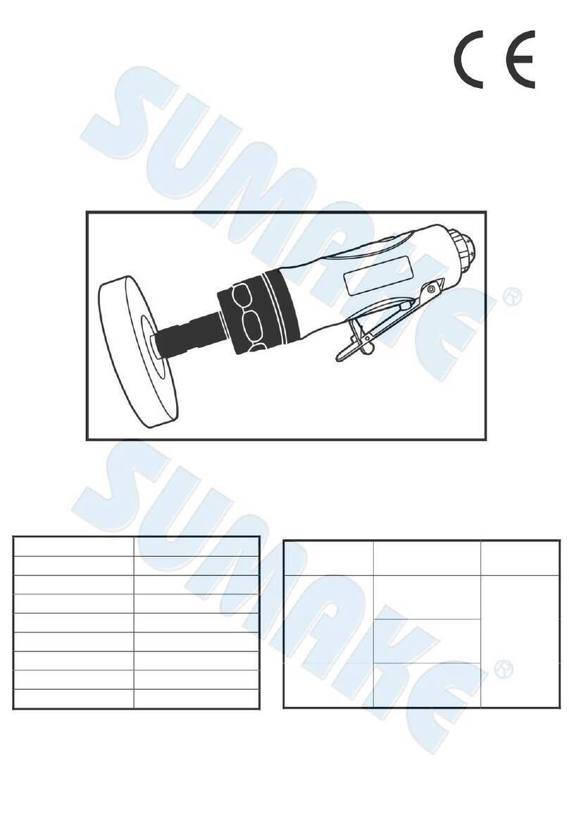
Sumake SMPRF48/O.E. User manual

.
SUMAKE PNEUMATIC TOOLS
Oil-Free Air Push To Start-Shut Off Air
Screwdriver (Environment Protect)
3 Air Ways - Reversible Type –
Test result according to EN ISO 11148-6:2012
SUMAKE INDUSTRIAL CO., LTD
4F,NO.351,Yangguang St.,Neihu District TAIPEI, TAIWAN, ZIP:114-91
MODEL
Vibration
EN ISO 28927-2
Noise : EN ISO 15744
Safety Instructions
Warning
Sound pressure level
Sound power level
SMPRF48/O.E.
No Load: 0.8 m/s2
No Load: 80 dB(A)
No Load: 91 dB(A)
1- Read this manual and
understand all safety
instructions before operation
the tool.
2- Wear an approved
ear-protector and gloves while
operating tool.
SMPRF50/O.E.
No Load: 0.8 m/s2
No Load: 80 dB(A)
No Load: 91 dB(A)
SMPRF55/O.E.
No Load: 1.0 m/s2
No Load: 79 dB(A)
No Load: 90 dB(A)
SMPRF60/O.E.
No Load: 0.9 m/s2
No Load: 80 dB(A)
No Load: 91 dB(A)
SMPRF65/O.E.
No Load: 0.9 m/s2
No Load: 80 dB(A)
No Load: 91 dB(A)
SMPRF68/O.E.
No Load: 0.9 m/s2
No Load: 81 dB(A)
No Load: 92 dB(A)
Uncertainty K= 1.5 m/s²
Uncertainty K= 3dB
SMPRF48(50)(55)(60)(65)(68)/O.E.-S-2304C-MIF

EC DECLARATION OF CONFORMITY
We: SUMAKE INDUSTRIAL CO., LTD.
4F, No. 351, Yangguang St., Neihu District, Taipei City, Taiwan
declare in sole responsibility that the equipment
Equipment:OIL-FREE AIR START-SHUT OFF AIR SCREWDRIVER
(ENVIRONMENT PROTECT) 3 AIR WAYS - REVERSIBLE TYPE -
Model/ Serial No.:SMPRF48(50)(55)(60)(65)(68)/O.E.
to which this declaration applies, complies with these normative documents:
Machinery Directive: 2006/42/EC
and conforms to the following EN standard,
EN ISO 12100: 2010
EN ISO 11148-6:2012
Name and Signature/Position Date and Place
2022/12/1
Mike Su –Managing Director Taipei, Taiwan
SMPRF48(50)(55)(60)(65)(68)/O.E.-D-2304B-MIF

Air Nutrunner Air Start Shut-off Operator’s Manual
1
For safety use, Please Follow the instructions. The operation without your local regulations may cause serious injury. Read thoroughly
and understand this instruction manual and keep this within reach for future reference.
CLASSIFIED CAPACITY SPECIFICATIONS
OPERATIONS
1. Precision adjustment has been made around case, gear and rotating section
2. M5 Signal port fitting is used for transmission of 1)Start signal of tools, and 2)Stop signal of torque.
3. Air start means automatic stop at torque set value and air supply stop of M5 signal port fitting and motor. You must stop
the air supply in order to reset the Air nutrunner motors to the initial status, then Air nutrunner motors will restart when air
supplied
4. Easy adjusting fastening torque by tightening or loosening nut torque indication.
5. Tighten to the right: increase torque. Loosen to the left: decrease torque
6. Air motor will automatically stop when the load reaches at the pre-set torque.
7. The color ring –for torque manages and identifies ………..Using site management.
8. To avoid defective of motor, please screw tight the tools at Locking space when fixing Air nutrunner motors.
9. Warning: In case O.E. type, Incorrect direction of air inlet(black) and air exhaust(silver) may causes defective of air nutrunner
motors .
AIR SUPPLY
1. Air tools are adversely affected by moisture. Since air from compressor contains much moisture and dust, it is desirable to
provide a filter and lubricator in the pipeline to remove such undesirable elements. Also take the drain out from air tank every
day.
2. When using brand-new air hose or air pipe. Blow and clean the inside of air hose or pipe before installation.
3. Keep inside of air hose or air pipe clean to prevent airdrop problem caused by the lots of drain and dust accumulated and
possibly make the inside diameter smaller in the long use.
4. When disconnect air hose from air tool while in the operation do not drop air hose end to the floor as dust or other element
may come into air hose.
5. Use air regulator to keep stable air pressure at 5.5kg/cm2-6.0kg/cm2 at the toll. It is important to get proper air pressure at
the toll.
6. After lubrication, oil will discharged the exhaust upon operation. Flush motor for a few seconds.
LUBRICATION
1. Lubrication is indispensable to air tolls. The most ideal maintenance is to install one lubricator to a toll for automatic oil feed,
but if it is not available, manual lubrication twice every day is recommended for longer life and keeping the efficient function
of mechanism.
2. For manual lubrication, disconnect air hose from bushing air inlet and full up spindle oil(#40-#60) into the air feed in take and
push the bit.
SMPRF48(50)(55)(60)(65)(68)/O.E.-I-2208B-MI
ModelNo.
Free
Speed
O.A.L
Dia.
Air hose bore
Air
Consumption
Torque
range
Vibration
Lever
Standard
Deviation
Fastening Capacity
Machine
Screw Dia.
Tapping
Screw Dia.
r.p.m
.
mm
mm
6.0 Kg/cm3
5.0 Kg/cm3
m3/min
Kgf-cm
Ms3
%
T
2T
SMPRF48/O.E.
1800
247
40
8.0
9.5
0.55
5-45
< 2.5
±3
M2.8-M5.8
M2.3-M4.7
SMPRF50/O.E.
1400
247
40
8.0
9.5
0.55
7-50
< 2.5
±3
M2.9-M6.0
M2.6-M4.9
SMPRF55/O.E.
1000
247
40
8.0
9.5
0.55
7-65
< 2.5
±3
M2.9-M6.4
M2.6-M5.4
SMPRF60/O.E.
550
247
40
8.0
9.5
0.55
15-95
< 2.5
±3
M4.1-M7.0
M3.3-M6.0
SMPRF65/O.E.
300
247
40
8.0
9.5
0.55
30-180
< 2.5
±3
M5.0-M9.3
M4.0-M7.2
SMPRF68/O.E.
250
247
40
8.0
9.5
0.55
50-280
< 2.5
±3
M6.0-M11.0
M4.9-M8.7

Air Nutrunner Air Start Shut-off Operator’s Manual
2
Installation diagram of Automation system with M5 signal port
【For 3 ports shutoff and air-start】
⚫By connecting with M5 signal port, PLC automation system can precise control the torque to avoid any float,
loose or miss occurred.
⚫Air screwdriver clutch will be released and motor will stop automatically when load reach the preset torque.
⚫Water filter, pressure regulator & oiler are the devices required upon tube configuration.
⚫In order to assure the tube from pressure interference, installation of quick exhaust valve is a must with the
use of the air tool.
⚫Connect M5 signal port with pressure sensor.
P=Pneumatic supply
A=Filter
B=Pressure regulator
C=Oil fog lubricator
D=Solenoid valve
E=Quick exhaust valve
F=M5pressure sensor
S=Pneumatic screwdriver
X1=1/4”PTsilver Hex vent
X2=1/4”PTblack Hex Inlet(lock)
X3=1/4”PTblack Hex Inlet(loosen)
M5=M5signal port

Air Nutrunner Air Start Shut-off Operator’s Manual
3
M5 port-Automated Signal Chart:
1. P1 appears when M5 Signal Port detects the pressure as the air tool switches on.
2. P0appears when M5 Signal Port turns off the pressure back to 0, when the torque has reached the target.
3. Central Processing Unit will determine on or off due to pressure by the sign of P1 or P0.
4. Ts1 < tolerance zone = float mode.
Ts2 within tolerance zone = lock torque.
Ts3 > tolerance zone = loose thread.
Air supply conditions & Do's and Don'ts:
1. There are some adverse effects for pneumatic tools when the air compressor contains too much water and
dust. Therefore, it is necessary that the pneumatic tubes equipped with water filter and automatic supply
lubricating oil to filter extra substances, and to drain water out of the drain tank.
2. Before the air screwdriver is installed, please connect inlet pipe and pipe coupling onto inlet nuts.
3. To prevent gathering too much water and dust on the pneumatic circuit and pipe coupling, please keep the
pipes clean or the inner diameter could possibly shrink in a long term use.
4. When the air screwdriver and the pneumatic tubes are detached, you must not drop the pneumatic tube
connector on the floor. This will gather dust and other extra substances into the pneumatic circuit and damage
the equipment.
5. In general, it is suggested that the pressure for main pneumatic circuit be 7.0kg/cm2or 8.0kg/cm2(100/140psi),
and to install pressure regulator before the air screwdriver is connected to the sub pneumatic circuit. The
pressure needs to be stabilized at 5.5kg/cm2or 6.0kg/cm2(80-90psi). If you choose the inner diameter for sub
pneumatic circuit as suggested in our chart, it will work for most of the screws. Please do not use the pressure
over the regulated one, otherwise it will shorten the life of the air screwdriver.
6. The installation of pressure regulator could stabilize the pressure of the pneumatic circuit, and to make sure
the accuracy of the air screwdriver twisting force(repeatability precision).
Maintenance note:
1. If the air screwdriver is not going to be used for a long time, please add lubricating oil for a better
preservation. Otherwise, the air screwdriver will be damaged and get rusty.
2. To use the FRL automatic lubricating tool could extend the life of the equipment.
SMPRF55/O.E.
OIL- FREE AIR PUSH TO START-SHUT OFF AIR SCREWDRIVER
(ENVIRONMENT PROTECT) 3 AIR WAYS - REVERSIBLE TYPE -
SMPRF55/O.E.-P-2102A-MI

SMPRF55/O.E.
OIL- FREE AIR PUSH TO START-SHUT OFF AIR SCREWDRIVER
(ENVIRONMENT PROTECT) 3 AIR WAYS - REVERSIBLE TYPE -
PARTS LIST
No. Parts No. Description Q'ty No. Parts No. Description Q'ty
1 5A6103 End Housing 1 2S5032 Air Inlet Bushing [PT] 2
2 7Q2010 O Ring 1 2S5032-1 Air Inlet Bushing [NPT] 2
3 2P6007 Valve 1 36 2S6103 Retainer 1
4 7S2111 Screw 1 37 7S2102 Ball 32
5 2Q2003 O Ring 1 38 3S5001 Pilot Pin 1
6 7S5001 Ball Bearing 1 39 3S5211 Rear Clutch 1
7 1S6004 End Plate 1 40 6N2006 C Ring 1
10 1P6011 Cylinder 1 41 3S5217 Center Clutch 1
12 1P6049 Oil Free Blade 6 42 7S2112 Ball 2
13 1P6063 Front Plate 1 43 3S5021 Anvil 1
14 7S2002 Ball Bearing 1 44 7S2105 Ball 2
15 6N2020 C Ring 1 45 6N5110 Spring 1
16 1S6052 14T Rotor 1 46 3S2227 Slide Base 1
19 1P2130 14T Plate Gear 4 47 3S5221 End Clutch 1
20 1P2290 Fourth Gear Cage 1 48 7S2102 Ball 25
21 1G6090 14T Main Gear 1 49 3S5231 Ball Race 1
22 1P6130 14T Plant Gear 4 50 6N2006 C Ring 1
23 1P6288 Fourth Gear Cage 1 51 6N5002 Torque Spring 1
24 1S6061 Internal Gear 1 52 2S5121 Washer 1
24-1 4W6023 Washer 1 53-1 3S2240 Anvil Bushing 1
25 5A6035 Center Housing 1 54 3A5232 Clutch Housing 1
26 7S6503 Ball Bearing 1 55 6S2010 Needle Pin 3
28 6S2005 Operating Rod 1 56 3S5101 Regulation Washer 1
29 6S2021 Valve Plate 1 57 3A6002 Torque Ring 1
30 7Q2006 O Ring 1 59 5S2001 Bit Slide Sleeve 1
31 6N2104 Cone Spring 1 59-1 7S3107 Ball 1
33 2Q5001 O Ring 3 60 6N2103 Spring 1
2S5031 Air Exhaust [PT] 1 61 6N2001 C Ring 1
2S5031-1 Air Exhaust [NPT] 1 62 5A6021 Rear Housing (Left) 1
SMPRF55/O.E.-P-2102A-MI
34
35
This manual suits for next models
5
Table of contents
Other Sumake Tools manuals

Sumake
Sumake ST-2407 User manual

Sumake
Sumake ST-66413 User manual

Sumake
Sumake SA-CL110 User manual

Sumake
Sumake ST-2310/RH User manual

Sumake
Sumake ST-2401SL User manual

Sumake
Sumake ST-2237/R User manual

Sumake
Sumake SF501 User manual

Sumake
Sumake STT-08B User manual

Sumake
Sumake ST-2516A User manual

Sumake
Sumake ST-P6634S User manual

Sumake
Sumake ST-2272 User manual

Sumake
Sumake ST-TAIS030 Series User manual

Sumake
Sumake ST-2553A User manual

Sumake
Sumake HR3 Series User manual

Sumake
Sumake ST-4011 User manual

Sumake
Sumake ST-2557 User manual

Sumake
Sumake ST-2272L User manual

Sumake
Sumake ST-6652F User manual

Sumake
Sumake SF30T Series User manual

Sumake
Sumake ST-2002A User manual