manuals.online logo
Brands
  1. Home
  2. •
  3. Brands
  4. •
  5. Sumake
  6. •
  7. Tools
  8. •
  9. Sumake ST-6652F User manual

Sumake ST-6652F User manual

SUMAKE PNEUMATIC TOOLS
Air Punch & Flange
Punch Dia. 5mm
ST-6652F
SUMAKE INDUSTRIAL CO., LTD
4F,NO.351,Yangguang St.,Neihu District TAIPEI, TAIWAN, ZIP:114-91
Specification:
Capacity
1.6 mm
Punch Hole
Dia. 5 mm
Overall Length
10” (255 mm)
Air Inlet (PT)
1/4” (6.35 mm)
Air Hose (I.D.)
3/8” (10 mm)
Air Pressure
90 psi (6.3 bar)
Net Weight
3.0 lbs (1.4 kg)
Noise and Vibration:
Vibration
EN ISO 20643
Noise
EN ISO 15744
Remark
No Load:
2.4 m/s²
Sound Pressure Level
No load: 71 dB(A)
Please always
wear ear
protector at
environment
noise level >
80 dB(A) due
to risk of
impaired
hearing!
Sound power level
No load: 82 dB(A)
Uncertainty
K= 1.5 m/s²
Uncertainty
K= 3dB
ST-6652F-S-2010C-CFF
ECDECLARATION OF CONFORMITY
We: SUMAKE INDUSTRIAL CO., LTD.
4F, No. 351, Yangguang St., Neihu District, Taipei City, Taiwan
declare in sole responsibility that the equipment
Equipment:AIR PUNCH & FLANGE PUNCH DIA. 5MM
Model/ Serial No.:ST-6652F
to which this declaration applies, complies with these normative documents:
Machinery Directive: 2006/42/EC
and conforms to the following EN standard,
EN ISO 12100: 2010
EN ISO 11148-10:2011
Name and Signature/Position Date and Place
2022/7/1
Mike Su –Managing Director Taipei, Taiwan
ST-6652F-D-2207C-CFF
Foreword
Sumake is a manufacturer and exporter of air tools
since established. We have devote all our efforts in
improving quality and tools?life. As well as the
noise and vibration of tools. Bring all of you
working efficiences, profits, and enjoy using the tool
is our principle.
Features
This tool is designed to meet an extremely wide
range of metal board to be connected with each other
by first press the rim of each other and punching
holes, then connect these two board by ways of
inserting screw and bolt into the holes.
1. Main Applications
This tool is perfect for compression and/or punching
die of iron, steel, cast iron, aluminum, nonferrous
metal made thin board.
2. Cautions for Use
2-1 Air pressure
Maximum performance is displayed at the proper
sanding speed, obtainable at a gauge pressure of 6.2
bar. Range-wise, this is an air pressure from 5 to 7
bar (70 to 100 psi)
57
2-2 Air line
Use a 3/8?air hose between the compressor and the
tool . Compressed air is cooled and its water content
separated, as soon as the air leaves the compressor.
Tool
Nipple
Coupler Recoil
hose
Leader
hose
Oiler Regulator
Water
separation Air
supply
Drain
daily
A portion of the water content, however, is
condensed in the piping, and can enter the tool
mechanism, and may cause trouble. So, install an air
filter and on oiler between the compressor and the
tool. Use a 3 HP or larger compressor for each
sander.
2-3 Air hose
Clean the hose with a blast of compressed air before
connecting the hose to air tool. This will prevent
both moisture and dust within the hose from entering
the tool and causing possible rust or malfunction. To
compensate for unusually long hose (over 25 ft), the
line pressure should be increased accordingly.
Drainage
2-4 Regular checks for cracks and fissures in the
Anvil, Clamb, Punch and Punching Die.
2-5 The approved eye protector, ear-muff, mouth-
muffle, and gloves should be worn when operate this
tool.
2-6 The working place shall beventilative.
2-7 Release the on-off device in the case of energy
supply failure.
2-8 Keep hands away from the compression
mechanism and it is better hold this tool by both
hands.
3. Operation, Adjusting And Replacing
Method
3.1 On-off device
To operate this tool, just push the lever toward the
tool itself. The Clamb move to the Anvil while push
the lever and move in the opposite direction while
release the lever. This tool operates once for one
single push-release cycle.
For the sake of safety, put it on hanger or on a soft
flat pad when not in use.
3.2 Replace and adjusting
There is no user serviceable part inside this tool.
Please send the tool to a qualified personnel or our
service section to repaire or/and replace worn parts.
4. Maintenance
4-1 Lubrication
Before connecting the hose , apply 4 or 5 drops of
#60 spindle oil at the air inlet. Apply Use of a thicker
oil can lead to reduced performance or malfunction.
If a thicker oil is used by accident, wipe it away
immediately. Also, every 3 or 4 hours of operation,
oiling is necessary. When necessa ry, the tool has to
be refilled with high quality hydraulic oil, like Shell
Teilus Oil C-10.
4-2 Storage
Avoid storing the tool in a location subject to high
humidity. If the tool is left as it is used , the residual
moisture inside the tool can cause rust. Before storing
and after operation, oil the tool at the air inlet with
spindle oil and run it for a short time.
4-3 Disposal
If the tool is too seriously damaged to be used
anymore, drop it in a resource recycling can. Never
drop it into fire.
4-4 Ordering service Parts
For further operational and handling information or
for replacement of parts and components, contact the
sale agent from whom you purchased the tool or the
service division of our company.
*In ordering parts and components, give each par t
number, name and quantity.
Warning
1. This tool is not insulted for coming into contact
with electric power source.
2. It is forbidden to use this tool in explosive
atmospheres and do not put any combustible material
near the workpiece since it emit spa rks when grind
with metal material.
3. Prevent long hair or loose clothing from drawing
in while operate this tool.
4. Never carry the tool by hose and beware of a
whipping compressed air hose.
ST-6652F-I-1103A-CF
ST-6652F AIR PUNCH & FLANGE PUNCH DIA. 5MM
PARTS LIST
No. Parts No. Description Q'ty No. Parts No. Description Q'ty
1 6652F-01 Clamp 1 20 6652F-20 Throttle Lever 1
2 6652F-02 Set Screw 1 21 6652F-21 Spring Pin 1
3 6652F-03 Punch Die 1 22 6652F-22 O-Ring 1
4 6652F-04 Guide Bushing 1 23 6652F-23 Push Rod 1
5 6652F-05 Cup Spring 13 24 6652F-24 Spring 1
6 6652F-06 Punch 1 25 6652F-25 Valve 1
7 6652F-07 Screw 2 26 6652F-26 Spring 1
8 6652F-08 Cover Plate 1 27 6652F-27 O-Ring 1
9 6652F-09 Anvil 1 28 6652F-28 Screw 1
10 6652F-10 Oil Seal 1 29 6652F-29 O-Ring 1
11 6652F-11 Support Ring 1 30 6652F-30 Support Ring 1
12 6652F-12 O-Ring 1 31 6652F-31 Hydr. Piston 1
13 6652F-13 Oil Plug 1 32 6652F-32 O-Ring 1
14 6652F-14 O-Ring 1 33 6652F-33 Support Ring 2
15 6652F-15 Hydr Cylinder 1 34 6652F-34 Spring 1
16 6652F-16 Air Cylinder 1 35 6652F-35 Piston 1
17 6652F-17 Plastic Wrapp 1 36 6652F-36 O-Ring 1
18 6652F-18 Valve Body 1 37 6652F-37 O-Ring 1
19 6652F-19 Air Inlet 1
ST-6652F-P-1103A-CF

Other Sumake Tools manuals

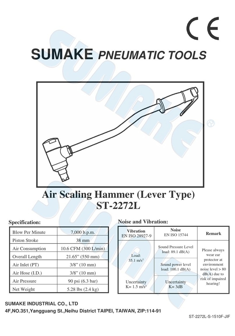
Sumake ST-2280 User manual

Sumake

Sumake ST-2280 User manual

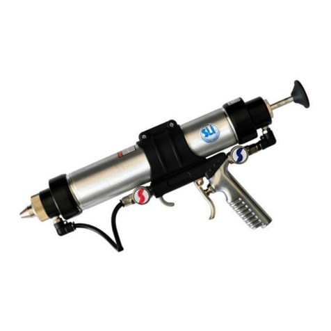
Sumake HR3 Series User manual

Sumake

Sumake HR3 Series User manual

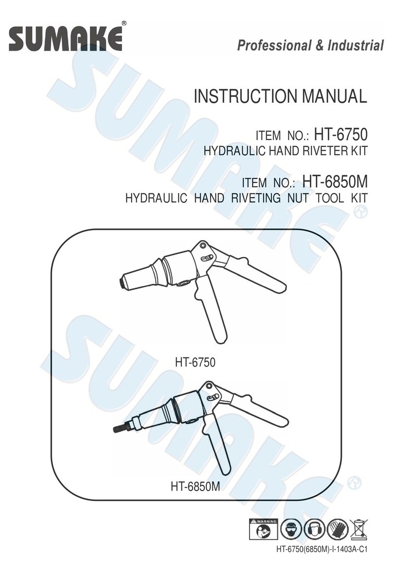
Sumake SA-4013 User manual

Sumake

Sumake SA-4013 User manual

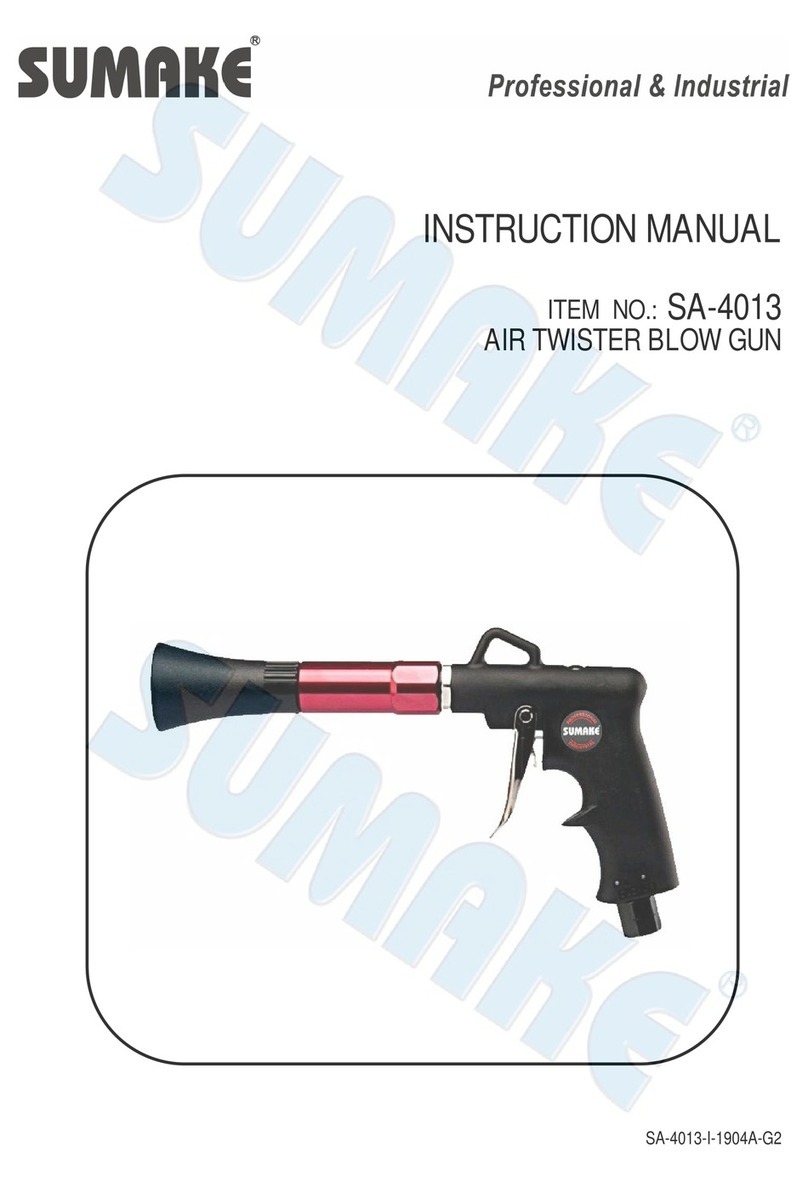
Sumake ST-2274 User manual

Sumake

Sumake ST-2274 User manual

Sumake STH-12A User manual

Sumake

Sumake STH-12A User manual

Sumake ST-2274S User manual

Sumake

Sumake ST-2274S User manual

Sumake ST-6410HR User manual

Sumake

Sumake ST-6410HR User manual

Sumake ST-2510 User manual

Sumake

Sumake ST-2510 User manual

Sumake SF30A Series User manual

Sumake

Sumake SF30A Series User manual

Sumake ST-2237/R User manual

Sumake

Sumake ST-2237/R User manual

Sumake ST-2560 User manual

Sumake

Sumake ST-2560 User manual

Sumake ST-2510A User manual

Sumake

Sumake ST-2510A User manual

Sumake ST-P6634 User manual

Sumake

Sumake ST-P6634 User manual

Sumake SF30T Series User manual

Sumake

Sumake SF30T Series User manual

Sumake ST-NH620 User manual

Sumake

Sumake ST-NH620 User manual

Sumake ST-NS11A-H User manual

Sumake

Sumake ST-NS11A-H User manual

Sumake ST-2404SL User manual

Sumake

Sumake ST-2404SL User manual

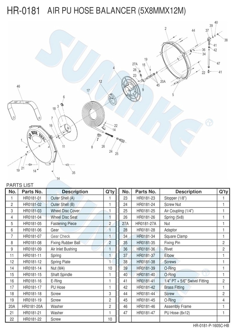
Sumake HR-0181 User manual

Sumake

Sumake HR-0181 User manual

Sumake ST-66409 User manual

Sumake

Sumake ST-66409 User manual

Sumake STT-08B User manual

Sumake

Sumake STT-08B User manual

Sumake ST-TB100 User manual

Sumake

Sumake ST-TB100 User manual

Sumake ST-2310/RH User manual

Sumake

Sumake ST-2310/RH User manual

Sumake ST-CH200R User manual

Sumake

Sumake ST-CH200R User manual

Sumake HR3 Series User manual

Sumake

Sumake HR3 Series User manual

Popular Tools manuals by other brands

Piper PA-32-301 Saratoga Maintenance manual

Piper

Piper PA-32-301 Saratoga Maintenance manual

TE Connectivity 2379255-1 instruction sheet

TE Connectivity

TE Connectivity 2379255-1 instruction sheet

Kobalt SGY-AIR266 Assembly instructions

Kobalt

Kobalt SGY-AIR266 Assembly instructions

WilTec XPOtool 64155 user manual

WilTec

WilTec XPOtool 64155 user manual

Foxwell ET2530 manual

Foxwell

Foxwell ET2530 manual

Paslode IM350+ Lithium General safety instructions

Paslode

Paslode IM350+ Lithium General safety instructions

RAMSET TRIX 160 Operator's manual and maintenance instructions

RAMSET

RAMSET TRIX 160 Operator's manual and maintenance instructions

Gardena RollUp M Operator's manual

Gardena

Gardena RollUp M Operator's manual

Granit 61099000 operating instructions

Granit

Granit 61099000 operating instructions

Parkside PSVH 56 A1 operating instructions

Parkside

Parkside PSVH 56 A1 operating instructions

London Emblem Badgeworx instruction manual

London Emblem

London Emblem Badgeworx instruction manual

Josef Kihlberg JK20 operating instructions

Josef Kihlberg

Josef Kihlberg JK20 operating instructions

Buffalo 320 manual

Buffalo

Buffalo 320 manual

Renishaw A-5514-8500 quick start guide

Renishaw

Renishaw A-5514-8500 quick start guide

Utility Solutions LOAD-RANGER USLR-XLT-1 Operation manual

Utility Solutions

Utility Solutions LOAD-RANGER USLR-XLT-1 Operation manual

Surtek RH405 manual

Surtek

Surtek RH405 manual

Aero AT-3 R100 Operating handbook

Aero

Aero AT-3 R100 Operating handbook

BGS technic 69506 instruction manual

BGS technic

BGS technic 69506 instruction manual

manuals.online logo
manuals.online logoBrands
  • About & Mission
  • Contact us
  • Privacy Policy
  • Terms and Conditions

Copyright 2025 Manuals.Online. All Rights Reserved.