Sumitomo HF-520 Series User manual

Power Transmission & Controls Group
Headquarter ThinkPark Tower, 1-1 Osaki 2-chome, Shinagawa-ku, Tokyo 141-6025, Japan
Specications, dimensions, and other items are subject to change without prior notice.
No.D2301E-1.2
EA04 Printed 2016.06
Worldwide Locations
U.S.A
Sumitomo Machinery Corporation of America
(SMA)
4200 Holland Blvd. Chesapeake, VA 23323, U.S.A.
TEL (1)757-485-3355 FAX (1)757-485-7490
Canada
SM Cyclo of Canada, Ltd. (SMC)
1453 Cornwall Road, Oakville, Canada ON L6J 7T5
TEL (1)905-469-1050 FAX (1)905-469-1055
Mexico
SM Cyclo de Mexico, S.A. de C.V. (SMME)
Av. Desarrollo 541, Col. Finsa, Guadalupe,
Nuevo León, México, CP67132
TEL (52)81-8144-5130 FAX (52)81-8144-5130
Brazil
Sumitomo Industrias Pesadas do Brasil Ltda.
(SHIB)
Rodovia do Acucar (SP-075) Km 26
Itu, Sao Paulo, Brasil
TEL (55)11-4886-1000 FAX (55)11-4886-1000
Chile
SM-Cyclo de Chile Ltda. (SMCH)
San Pablo 3507, Quinta Normal, Santiago, Chile
TEL (56)2-892-7000 FAX (56)2-892-7001
Argentina
SM-Cyclo de Argentina S.A. (SMAR)
Ing. Delpini, 2236 Area de Promocion el Triangulo,
Partido Malvinas Argentinas Grand Bourg,
Buenos Aires, Argentina B1615KGB
TEL (54)3327-45-4095 FAX (54)3327-45-4099
Guatemala
SM Cyclo de Guatemala Ensambladora, Ltda.
(SMGT)
Parque Industrial Unisur, 0 Calle B 19-50 Zona 3,
Bodega D-1 Delta Bárcenas en Villa Nueva, Guatemala
TEL (502)6648-0500 FAX (502)6631-9171
Colombia
SM Cyclo Colombia, S.A.S. (SMCO)
Carrera 11, No.93A-53, Ofce 203, Bogotá, Colombia
TEL (57)1-3000673
Germany
Sumitomo (SHI) Cyclo Drive Germany GmbH
(SCG)
Cyclostraße 92, 85229 Markt Indersdorf, Germany
TEL (49)8136-66-0 FAX (49)8136-5771
Austria
Sumitomo (SHI) Cyclo Drive Germany GmbH
(SCG)
SCG Branch Austria Ofce
Gruentalerstraße 30A, 4020 Linz, Austria
TEL (43)732-330958 FAX (43)732-331978
Belgium
Sumitomo (SHI) Cyclo Drive Germany GmbH
(SCG)
SCG Branch Benelux Ofce
Heikneuterlaan 23, 3010 Kessel-Lo, Leuven, Belgium
TEL (32)16-60-83-11 FAX (32)16-60-16-39
France
SM-Cyclo France SAS (SMFR)
8 Avenue Christian Doppler, 77700 Serris, France
TEL (33)164171717 FAX (33)164171718
Italy
SM-Cyclo Italy Srl (SMIT)
Via dell' Artigianato 23, 20010 Cornaredo (MI), Italy
TEL (39)293-481101 FAX (39)293-481103
Spain
SM-Cyclo Iberia, S.L.U. (SMIB)
C/Landabarri No. 3, 6° B, 48940 Leioa, Vizcaya, Spain
TEL (34)9448-05389 FAX (34)9448-01550
Sweden
SM-Cyclo Scandinavia AB (SMSC)
Industrigatan 21B, 234 35 Lomma, Sweden
TEL (46)40220030
United Kingdom
SM-Cyclo UK Ltd. (SMUK)
Unit 29, Bergen Way, Sutton Fields Industrial Estate,
Kingston upon Hull, HU7 0YQ, East Yorkshire,
United Kingdom
TEL (44)1482-790340 FAX (44)1482-790321
Turkey
SM Cyclo Turkey Güç Aktarım Sis. Tic. Ltd. Sti.
(SMTR)
Büyükdere Çayırbaşı Cd. Dede Yusuf Sk. No: 11,
34453 Sarıyer Istanbul, Turkey
TEL (90)216-384-4482 FAX (90)216-384-4482
China
Sumitomo (SHI) Cyclo Drive China, Ltd. (SCT)
11F, SMEG Plaza, No. 1386 Hongqiao Road,
Changning District, Shanghai, China (P.C. 200336)
TEL (86)21-3462-7877 FAX (86)21-3462-7922
Hong Kong
SM-Cyclo of Hong Kong Co., Ltd. (SMHK)
Rm 1301, CEO Tower, 77 Wing Hong Street,
Cheung Sha Wan, Kowloon, Hong Kong
TEL (852)2460-1881 FAX (852)2460-1882
Korea
Sumitomo (SHI) Cyclo Drive Korea, Ltd. (SCK)
Royal Bldg. 9F Rm. 913, 5 Danju-Dong, Chongro-Ku,
Seoul, Korea 110-721
TEL (82)2-730-0151 FAX (82)2-730-0156
Taiwan
Tatung SM-Cyclo Co., Ltd. (TSC)
22 Chungshan N. Road 3rd., Sec. Taipei, Taiwan 104,
R.O.C.
TEL (886)2-2595-7275 FAX (886)2-2595-5594
Singapore
Sumitomo (SHI) Cyclo Drive Asia Pacic Pte.
Ltd. (SCA)
15 Kwong Min Road, Singapore 628718
TEL (65)6591-7800 FAX (65)6863-4238
Philippines
Sumitomo (SHI) Cyclo Drive Asia Pacic Pte.
Ltd. (SCA)
Philippines Branch Ofce
B2B Granville Industrial Complex, Carmona,
Cavite 4116, Philippines
TEL (63)2-584-4921 FAX (63)2-584-4922
TEL (63)46-430-3591
TEL (63)46-438-20579 - 81
Vietnam
SM-Cyclo (Vietnam) Co., Ltd. (SMVN)
Factory 2B, Lot K1-2-5, Road No. 2-3-5A,
Le Minh Xuan Industrial Park, Binh Chanh Dist.,
HCMC, Vietnam
TEL (84)8-3766-3709 FAX (84)8-3766-3710
Malaysia
SM-Cyclo (Malaysia) Sdn. Bhd. (SMMA)
No.7C, Jalan Anggerik Mokara 31/56, Kota Kemuning,
Seksyen 31, 40460 Shah Alam, Selangor Darul Ehsan,
Malaysia
TEL (60)3-5121-0455 FAX (60)3-5121-0578
Indonesia
PT. SM-Cyclo Indonesia (SMID)
Jalan Sungkai Blok F 25 No. 09 K, Delta Silicon 5,
Lippo Cikarang, Bekasi 17530, Indonesia
TEL (62)21-2961-2100 FAX (62)21-2961-2211
Thailand
SM-Cyclo (Thailand) Co., Ltd. (SMTH)
1 Empire Tower, Unit 2103-4, 21st Floor, South Sathorn
Road, Yannawa, Sathorn, Bangkok 10120, Thailand
TEL (66)2670-0998 FAX (66)2670-0999
Australia
Sumitomo (SHI) Hansen Australia Pty. Ltd.
(SHAU)
181 Power St, Glendenning, NSW 2761, Australia
TEL (61)2-9208-3000 FAX (61)2-9208-3050
India
Sumi-Cyclo Drive India Private Limited
(SMIN)
Survey No. 130, Hissa No. 02, Jeevan Nagar,
Off Mumbai-Bangalore Bypass, Tathawade,
Pune - 411033, India
TEL (91)20-6674-2900 FAX (91)20-6674-2901
Japan
Sumitomo Heavy Industries, Ltd. (SHI)
ThinkPark Tower, 1-1 Osaki 2-chome, Shinagawa-ku,
Tokyo 141-6025, Japan
TEL (81)3-6737-2511 FAX (81)3-6866-5160
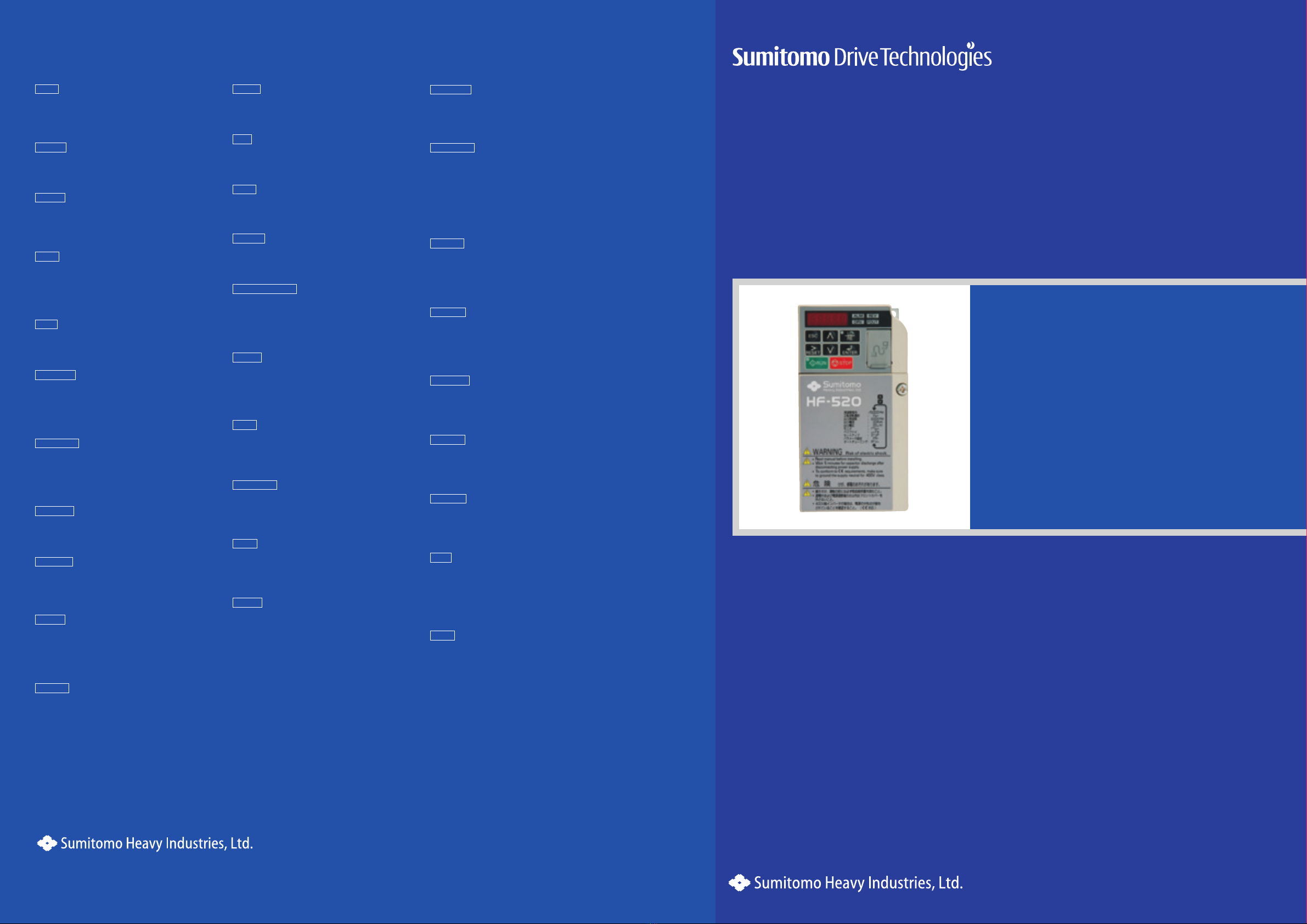
Sensorless Vector Inverter
HF-520 series
No.D2301E-1

1
HF-520 series : The user friendly Sensorless Vector
Control Drive!
Powerful Inverter suitable for SUMITOMO Gearmotor
Sensorless vector control allows for high starting torque.
Deceleration time can be shortened by the overexcitation operation of braking
function.
This inverter is ideal for SUMITOMO Gearmotor operation.
Easy Parameter Setting for the Application
The most suitable parameters are pre-set automatically by choosing the type of
applications such as conveyor, lifter and etc.
This will help to reduce testing and commissioning time.
Easy Parameter Management
A copy of the parameter values settings by the LED operator can be used to
transfer to other inverters.
Parameter setting le can be managed using Engineering Tool for PC.
Long Lifetime Inverter
The capacitor and cooling fan are designed for long lifetime operation (10 years).
Maintenance time can be checked by LED operator.
Corresponds to major standards of the world
< Table of Contents >
Explanation of Functions ……………………… 1~2
Operation …………………………………… 3~4
Standard and Common Specications ………… 5
Standerd Connection Diagram ………………… 6
Terminal Functions …………………………… 7
Applied Connection Diagram ………………… 8
Table of Parameters ………………………… 9~12
Outline Drawing ……………………………… 13

2
Power Range
Voltage Class
(Input/Rated output)
Applicable Motor (kW)
0.2 0.4 0.75 1.5 2.2 3.7 5.5 7.5
3-phase 200V/3-phase 200V
3-phase 400V/3-phase 400V
1-phase 200V/3-phase 200V
Model No.
Gearmotor Product Lineup
CYCLO® HYPONIC Gearmotor® PREST® NEO Gearmotor
HF520 :HF-520 series
Power supply
2 : 3-phase 200V
4 : 3-phase 400V
S : 1-phase 200V
HF520 2 − A20
Output power
A20 : 0.2kW 1A5 : 1.5kW 5A5 : 5.5kW
A40 : 0.4kW 2A2 : 2.2kW 7A5 : 7.5kW
A75 : 0.75kW 3A7 : 3.7kW
HF-520 series
Bevel BUDDYBOX® and Helical BUDDYBOX® which can be driven by HF-520 too.
Applicable Wiring for Accessories and Options … 14
Peripheral Equipment ………………………… 15
External Options …………………………… 16~21
Notes to Inverter Users ……………………… 22~24
Selection Guide ……………………………… 25
Warranty …………………………………… 26

3
Operation
LED On Flashing Off
LED Display
STOP Key
Stop the drive.
LED Display
REV
FOUT
DRV
ALM
ENTER Key
Select all modes, parameters,
settings, etc.
Select a menu item to move from
one display screen to the next.
Data Display Area
(5-digit)
Displays frequency, parameter
number, and other data.
LO/RE Lamp
Light to indicate that the
operator is set to LOCAL.
ESC Key
Return to the previous menu.
Easy Operation
Used as a quick guide for the
abbreviations used on the
display screen.
RESET & SHIFT Key
Resets to clear a fault situation.
Move the cursor to the right.
RUN Lamp
Light while the drive is operating
the motor.
RUN Key
Start the drive.
Communication Port
Port used for LED Operator.
Up Key
Scroll up to select parameter
numbers, setting values, etc.
Down Key
Scroll down to select parameter
numbers, setting values, etc.
LO/RE Selection Key
Switch drive control between the
operator (LOCAL) and
the control terminals (REMOTE).
When the inverter
detect the alarm
• When an alarm occurs
• OPE (Operation Error) detected
•
When a fault or error occurs during Auto-Tuning
• During deceleration to stop
• When the Run command is input and
the frequency reference is 0.
Motor is rotating in reverse
Drive Mode.
• Drive Mode
• Auto-Tuning
Display output frequency (Hz)
When the Run command is selected from
the LED operator (LOCAL).
During run
Normal state
Motor Forward rotation
Programming mode
Display except output frequency
Other than LED operator
(REMOTE)
During stop

4
Operation
LED Operator Screen Structure
Conveyor Application
No. Parameter Name Default Setting
A1-02 Control Method Selection 0 : V/f Control
C1-01 Acceleration Time 1 3.0 s
C1-02 Deceleration Time 1 3.0 s
C6-01 Drive Duty Selection (ND/HD) 0 : Heavy Duty (HD)
L3-04 Stall Prevention Selection during Deceleration 1 : Enabled
1
2
3
4
DRV
5
6
7
8
9
10
11
Tum the power on
Drive Condition Setting
• Local Mode
• Frequency Reference Setting
Forward/Reverse
Output Frequency
Output Current
Output Volage
Monitor Display
Verify Mode
Set Up Mode
Parameter Setting Mode
Auto-Tuning Mode
Return Frequency Reference
Setting
Flashing
Flashing
Flashing
When the parameter change is possible, display is flashing.
Step DisplayKey Operation Step DisplayKey Operation
Step DisplayKey Operation
< Frequency Reference Setting >
Frequency Reference
Writing of Frequency
Reference
After “End” display
Green Light
Monitor Mode : Condition monitor, Alarm and Alarm history
Select the monitor item
Monitor U1-O1
(Frequency Reference)
Select another monitor item
Push
Push
Verify Mode :
Check the edited parameter.
Check the value of the
edited parameter.
LO Light
Return to the verify menu.
After pressing one more ESC Key, return to the initial display.
The Verify Menu lists edited parameters from the Programming
Mode or as a result of Auto-Tuning.
Drive Mode :
Structure for LED Operator
Monitor the operation status of the drive
(Frequency reference, Output frequency, Output current, Output voltage, etc.).
Return the monitor mode
display
The application Presets function is applicable.
The parameters are changed to the optimum value for each application.
Setup Mode

5
Standard and Common Specications
Standard Specications
Item Specifications
Input Voltage Class 3-phase 200V / 3-phase 400V / 1-phase 200V
Applicable Motor (kW) 0.2 0.4 0.75 1.5 2.2 3.7 5.5 7.5
Rating
Input Voltage Class Model No. HF520 -
3-phase 200V HF5202-
A20 A40 A75 1A5 2A2 3A7 5A5 7A5
3-phase 400V HF5204-
1-phase 200V HF520S- - - -
Rated Output Capacity (kVA) 200V class 0.6 1.1 1.9 3.0 4.2 6.7 9.5 12.6
400V class 0.9 1.4 2.6 3.7 4.2 7.0 11.3 13.7
Rated Output Capacity (A)
3-phase 200V input 1.6 3.0 5.0 8.0 11.0 17.5 25.0 33.0
3-phase 400V input 1.2 1.8 3.4 4.8 5.5 9.2 14.8 18.0
1-phase 200V input 1.6 3.0 5.0 8.0 11.0 - - -
Output Voltage 3-phase 200V~240V (200V class) / 3-phase 380~480V (400V class)
Over Load Current Rating 150% 1 minute
Power Supply
Voltage Frequency
3-phase 200V 3-phase 200V~240V 50/60Hz
3-phase 400V 3-phase 380V~480V 50/60Hz
1-phase 200V 1-phase 200V~240V 50/60Hz
Allowable Fluctuation Voltage -15~+10%, Frequency±5%
Protective Method Enclosed Type IP20 Enclosed Type
(NEMA Type1)
Cooling Method
3-phase 200V Self-cooling Cooling fan
3-phase 400V Self-cooling Cooling fan
1-phase 200V Self-cooling Cooling fan -
Common Specications
Item Specifications
Control Characteristics
Control Method Sensorless Vector Control , V/f Control
Frequency Control Range 0.01 to 400 Hz
Frequency Accuracy Digital input: within ±0.01% of the max output frequency (-10 to +50 °C)
Analog input: within ±0.5% of the max output frequency (25 °C ±10 °C)
Frequency Setting Resolution Digital inputs: 0.01 Hz
Analog inputs: 1/1000 of maximum output frequency
Output Frequency Calculation
Resolution
1/220 x Maximum output frequency (E1-04)
Frequency Setting Signal Main frequency reference: 0 to +10 Vdc (20 kΩ), 4 to 20 mA (250 Ω),0 to 20 mA (250 Ω)
Main speed reference: Pulse Train Input (max 32 kHz)
Torque Limit Sensorless Vector Control only. Adjustable in 4 quadrants.
Accel/Decel Time 0.00 to 6000.0 s (allows four separate settings for accel and decel)
Braking Torque Instantaneous Average Decel Torque <2> : 0.1/0.2 kW: over 150%, 0.4/0.75 kW: over 100%, 1.5 kW: over 50%, 2.2 kW and above:
over 20% Continuous Regen Torque: 20%, 125% with a Braking Resistor Unit <3> : (10% ED) 10 s with an internal braking resistor.
V/f Characteristics Preset V/f patterns and user-set program available.
Functions
Momentary Power Loss Ride-Thru,Speed Search Over/Undertorque Detection,Torque Limit, Multi-Step Speed (17 steps max)
Accel/Decel Time Switch,S-Curve Accel/Decel,2-Wire/3-Wire Sequence,Rotational Auto-Tuning Stationary Auto-Tuning of Line-
to-Line Resistance,Dwell,Cooling Fan ON/OFF,Slip Compensation Torque Compensation,Jump Frequencies (reference dead
band) Frequency Reference Upper/Lower Limit,DC Injection Braking (start and stop), High Slip Braking PID Control (with Sleep
Function),Energy Saving,MEMOBUS/Modbus (RS-485/RS-422) Fault Reset,Parameter Copy,Fault Restart,Removable Terminals with
Parameter Backup Function
Carrier Frequency 5 kHz (user-adjustable from 2 to 15 kHz)
Protection Functions
Motor Protection Motor overheat protection via output current sensor
Overcurrent Protection Drives stops when output exceeds 200% of the rated current
Overload Protection A stop command will be entered after operating at 150% for 60 s
Overvoltage Specification 200 V Class: Stops when DC bus voltage exceeds approx. 410 V
400 V Class: Stops when DC bus voltage exceeds approx. 820 V
Low Voltage Protection
Drive stops when DC bus voltage falls below the levels indicated: <5>
190 V (3-phase 200 V), 160 V (single-phase 200 V)
380 V (3-phase 400 V), 350 V (3-phase 380 V)
Momentary Power Loss
Ride-Thru
3 selections available: Ride-Thru disabled (stops after 15 ms), time base of 0.5 s, and continue running as long as the drive control
board is powered up.
Heatsink Overheat Protection Protected by thermistor
Stall Prevention Stall prevention is available during acceleration, deceleration, and duringrun. Separate settings
for each type of stall prevention determine the current level at which stall prevention is triggered
Ground Fault Protection Electronic circuit protection
DC Bus Charge LED Remains lit until DC bus voltage falls below 50 V
Environment
Storage/Installation Area Indoors
Ambient Temperature IP20/NEMA Type 1 enclosure: -10 °C to +40 °C
IP20/IP00 Open-Chassis enclosure: -10 °C to +50 °C
Storage Temperature -20 to +60 °C allowed for short-term transport of the product
Humidity 95% RH or less with no condensation
Altitude Up to 1000 meters without derating; up to 3000 meters with output current and voltage derating.
Shock, Impact 10 to 20 Hz: 9.8 m/s2
20 to 55 Hz: 5.9 m/s2
Note 1: Instantaneous average deceleration torque refers to the torque required to decelerate the motor (uncoupled from the load) from the rated motor speed down to zero in the shortest
time.
Note 2: Ensure that Stall Prevention Selection during Deceleration is disabled (L3-04 = 0) or set to 3 when using a regenerative braking resistor.
Note 3: Overload protection may be triggered when operating with 150% of the rated output current if the output frequency is less than 6 Hz.

6
Standard Connection Diagram
M
P1 P
R/L1
S/L2
T/L3
U/T1
V/T2
W/T3
S1
S2
S3
S4
S5
S6
S7
+24 V
S3
Dip Switch SINK
SOURCE
SC
Shield Ground
Terminal
MA
P1
P2
MB
MC
MP
AM
AC
PC
200~240V
50/60Hz
Option Card
Connector
Dip Switch S1
VI
HC
H1
U
V
W
Pulse Train Input
(max. 32kHz)
+10.5V max. 20mA
Frequency Reference
Setting Potentiometer
R
S
T
RP
+V
A1
A2
AC
R+
R–
S+
S–
IG
3 Phase
Power Supply HF-520
DC Reactor
(Option)
Jumper
Regenerative Braking Resistor
(Option)
–
+1+2
During Run
Frequency Agree
MEMOBUS
RS-485/422
AC250V 10 mA to 1A
DC30V 10 mA to 1A
Safety Switch
Dip
Switch
S2
Shield Ground Terminal
Jumper Safety Disable Input
DC5~48V, 50mA max.
Terminator
Resistor
Forward Run/Stop
Fuse
AC Reactor
Reverse Run/Stop
External Fault
Fault Reset
Multi-step Speed 1
Multi-step Speed 2
Jog Reference
0~+10V (20kΩ)
1kΩ
3
2
1
0~+10V (20kΩ)
4~20mA (250Ω)/
0~20mA (250Ω)
120 Ω,
1/2 W
(
(
+24 V 8 mA
Analog Monitor Output
DC0~+10V (2mA)
Pulse Train Output
0~32kHz
+
-
Common
Shielded Wire Twisted-Pair Shielded Wire
Main Circuit Control Circuit
Thermal Relay
B1B2
Fault
10Ω or less (400V class)
100Ω or less (200V class)
AM

7
Terminal Functions
Main Terminals
No. Terminal Name Function
R/L1
Main circuit power supply input
Connects line power to the drive.
Drives with single-phase 200 V input power use terminals R/ L1 and S/L2 only.
T/L3 must not be used.
S/L2
T/L3
U/T1
Drive output Connects to the motor.V/T2
W/T3
B1 Regenerative braking resistor Available for connecting a regenerative braking resistor.
B2
+1 DC reactor connection These terminals are shorted at shipment.
Remove the shorting bar between +1 and +2 when connecting a DC reactor to this terminal.
+2
+1 DC power supply input For connecting a DC power supply.
–
(2 terminals) Ground
Grounding Terminal
200V Class 100Ω or less
400V Class 10Ω or less
Input Terminals
Type No. Terminal Name (Function) Function (Signal Level)
Multi-Function
Digital Inputs
S1 Multi-function input 1
(Closed: Forward run, Open: Stop)
Photocoupler
24 Vdc, 8 mA
Note: Drive preset to sinking mode. When using source mode, set DIP switch S3 to allow for a 24
Vdc (±10%) external power supply.
S2 Multi-function input 2
(Closed: Reverse run, Open: Stop)
S3 Multi-function input 3 (External fault (N.O.)
S4 Multi-function input 4 (Fault reset)
S5 Multi-function input 5
(Multi-step speed reference 1)
S6 Multi-function input 6
(Multi-step speed reference 2)
S7 Multi-function input 7 (Jog reference)
SC Multi-function input common
(Control common) Sequence common
Safe Disable
Input
HC Power supply for safe disable input +24 Vdc (max 10 mA allowed)
H1 Safe disable input Open: Output disabled
Closed: Normal operation
Main
Frequency
Reference
Input
RP Multi-function pulse train input
(frequency reference)
Response frequency: 0.5 to 32 kHz
(Duty Cycle: 30 to 70%)
(High level voltage: 3.5 to 13.2 Vdc)
(Low level voltage: 0.0 to 0.8 Vdc)
(input impedance: 3 kΩ)
+V Analog input power supply +10.5 Vdc (max allowable current 20 mA)
A1 Multi-function analog input 1
(frequency reference) Input voltage 0 to +10 Vdc (20 kΩ) resolution 1/1000
A2 Multi-function analog input 2
(frequency reference)
Input voltage or input current (Selected by DIP switch S1) 0 to +10 Vdc (20 kΩ),
Resolution: 1/1000 4 to 20 mA (250 Ω) or 0 to 20 mA (250 Ω),
Resolution: 1/500
AC Frequency reference common 0 V
Output Terminals
Type No. Terminal Name (Function) Function (Signal Level) Default Setting
Multi-Function
Digital Output
MA N.O. (fault) Digital output
30 Vdc, 10 mA to 1 A; 250 Vac, 10 mA to 1 A
Minimum load: 5 Vdc, 10 mA (reference value)
MB N.C. output (fault)
MC Digital output common
Multi-Function
Photocoupler
Output
P1 Photocoupler output 1 (During run)
Photocoupler output 48 Vdc, 2 to 50 mA <2>P2 Photocoupler output 2 (Frequency agree)
PC Photocoupler output common
Monitor Output
MP Pulse train output (Output frequency) 32 kHz (max), DC5-12V (50% duty)
AM Analog monitor output 0 to 10 Vdc (2 mA or less) Resolution: 1/1000
AC Monitor common 0 V

8
Applied Connection Diagram
Operation by Current Signal (4-20mA)
When terminal S5 is used as a current/Voltage signal (Frequency reference setting potentiometer)
Changeover signal input.
ACL
U
V
W
X
Y
Z
MCB
Power
Supply
Tx
FU
Stop Run
RN
RN
RN
Current signal
Forword
AU
AU
(Note2)
Manual (Frequency setting)
Auto (Current signal) MB
MC
S1
S5
SC
+V
A1
AC
A2
Note 1 Set parameter b1-01 to “1: Frequency Reference Selection 1”.
Set parameter H1-05 to “3: Multi-Function Digital Input Terminal S5 Function Selection”.
Set parameter H3-02 to “0: A1 Frequency Bias”.
Set parameter H3-09 to “2: Terminal A2 Signal Level Selection”.
Set parameter H3-10 to “2: A2 Auxiliary Frequency Reference”.
Set dip switch S1 on I side. (Current input)
Note 2 Install a step-down transformer when the power is 400 V-class.
Note 3 Connect the earth for shielded wire to the ground.
Frequency Reference
Setting Potentiometer
1kΩ
Current signal
DC4–20mA
+
–
Frequency meter
10V F.S.
+
FM
–
AM
AC
IM
Ground
Twisted wire
Shieided wire
HF-520
R/L1
S/L2
T/L3
U/T1
V/T2
W/T3
(Note3)
MCB
Power
Supply
Forward rotation
Reverse rotation
Multi-stage speed 1
Multi-stage speed 2
Multi-stage speed 3
Multi-stage speed 4
IM
S1
S2
S5
S6
S4
S7
SC
Shielded wire
Multi-stage
Speed 1
Parameter Setting
Multi-stage
Speed 2
Multi-stage
Speed 3
Multi-stage
Speed 4
H1-05=3
H1-06=4
H1-04=5
H1-07=32
Frequency
setting
Multi-stage
Speed 2
Multi-stage
Speed 1
Multi-stage
Speed 3
Multi-stage
Speed 4
d1-01
d1-03
d1-02
d1-04
d1-05
d1-06
d1-07
d1-08
d1-09
d1-10
d1-11
d1-12
d1-13
d1-14
d1-15
d1-16
× × × ×
× × ×
× × ×
× ×
× × ×
× ×
× ×
×
× × ×
× ×
× ×
×
× ×
×
×
Frequency setting by external signal
(×......Open, ......Closed)
U X
Y
Z
V
W
HF-520
R/L1
S/L2
T/L3
U/T1
V/T2
W/T3
Multispeed Operation (16-Step Speed)

9
Table of Parameters
Function
No. Name Range Def. *1Control Mode
V/f
SV
Initialization
Parameters
A1-01 Access Level Selection 0 ~ 2 2
A1-02 Control Method Selection 0,2 0 S S
A1-03 Initialize Parameters 0 ~ 5550 0
A1-04 Password 0 ~ 9999 0
A1-05*2Password Setting 0 ~ 9999 0
A1-06 Application Preset 0 ~ 8 0
User
Parameters
A2-01 ~
A2-32
User Parameters, 1 to 32 b1-01 ~
o2-08 -
A2-33 User Parameter Automatic Selection 0,1 1
Operation Mode Selection
b1-01 Frequency Reference Selection 1 0 ~ 4 1 S S
b1-02 Run Command Selection 1 0 ~ 3 1 S S
b1-03 Stopping Method Selection 0 ~ 3 0 S S
b1-04 Reverse Operation Selection 0,1 0
b1-07 LOCAL/REMOTE Run Selection 0,1 0
b1-08 Run Command Selection
while in Programming Mode 0 ~ 2 0
b1-14 Phase Order Selection 0,1 0
b1-15 Frequency Reference Selection 2 0 ~ 4 0
b1-16 Run Command Selection 2 0 ~ 3 0
b1-17 Run Command at Power Up 0,1 1
DC Injection Braking
b2-01 DC Injection Braking Start Frequency 0.0 ~ 10.0 0.5 Hz
b2-02 DC Injection Braking Current 0 ~ 75 50%
b2-03 DC Injection Braking Time/
DC Excitation Time at Start 0.00 ~ 10.00 0.00 s
b2-04 DC Injection Braking Time at Stop 0.00 ~ 10.00 0.00 s
b2-08 Magnetic Flux Compensation Value 0 ~ 1000 0% ×
Speed Search
b3-01 Speed Search Selection at Start 0,1 0
b3-02 Speed Search Deactivation Current 0 ~ 200 120
b3-03 Speed Search Deceleration Time 0.1 ~ 10.0 2.0 s
b3-05 Speed Search Delay Time 0.0 ~ 100.0 0.2 s
b3-06
Output Current 1 during Speed Search
0.0 ~ 2.0 *4
b3-08
Current Control Gain during Speed Search
(Speed Estimation Type) 0.00 ~ 6.00 0.5
b3-10 Speed Search Detection
Compensation Gain 1.00 ~ 1.20 1.05
b3-14 Bi-Directional Speed Search Selection 0,1 0
b3-17 Speed Search Restart Current Level 0 ~ 200 150%
b3-18 Speed Search Restart Detection Time 0.00 ~ 1.00 0.10 s
b3-19 Number of Speed Search Restarts 0 ~ 10 3
b3-24 Speed Serch Method Selection 0,1 0
b3-25 Speed Serch Retry Interval Time 0 to 30.0 0.5 s
Timer
b4-01 Timer Function On-Delay Time 0.0 ~ 300.0 0.0 s
b4-02 Timer Function Off-Delay Time 0.0 ~ 300.0 0.0 s
PID Control
b5-01 PID Function Setting 0 ~ 4 0
b5-02 Proportional Gain Setting (P) 0.00 ~ 25.00 1.00
b5-03 Integral Time Setting (I) 0.0 ~ 360.0 1.0 s
b5-04 Integral Limit Setting 0.0 ~ 100.0 100.0%
b5-05 Derivative Time (D) 0.00 ~ 10.00 0.00 s
b5-06 PID Output Limit 0.0 ~ 100.0 100.0%
b5-07 PID Offset Adjustment -100.0 ~+100.0 0.0%
b5-08 PID Primary Delay Time Constant 0.00 ~ 10.00 0.00 s
b5-09 PID Output Level Selection 0,1 0
b5-10 PID Output Gain Setting 0.00 ~ 25.00 1.00
b5-11 PID Output Reverse Selection 0,1 0
b5-12 PID Feedback Reference Missing
Detection Selection 0 ~ 5 0
b5-13 PID Feedback Loss Detection Level 0 ~ 100 0%
b5-14 PID Feedback Loss Detection Time 0.0 ~ 25.5 1.0 s
b5-15 PID Sleep Function Start Level 0.0 ~ 400.0 0.0 Hz
b5-16 PID Sleep Delay Time 0.0 ~ 25.5 0.0 s
b5-17 PID Accel/Decel Time 0 ~ 255 0 s
b5-18 PID Setpoint Selection 0,1 0
Function
No. Name Range Def. *1Control Mode
V/f
SV
PID Control
b5-19 PID Setpoint Value 0.00 ~ 100.00 0.00%
b5-20 PID Setpoint Scaling 0 ~ 3 1
b5-34 PID Output Lower Limit -100.0 ~ 100.0 0.0%
b5-35 PID Input Limit 0 ~ 1000.0
1000.0%
b5-36 PID Feedback High Detection Level 0 ~ 100 100%
b5-37
PID Feedback High Level Detection Time
0.0 ~ 25.5 1.0 s
b5-38 PID Setpoint / User Display 1 ~ 60000 *4
b5-39 PID Setpoint Display Digits 0 ~ 3
b5-40
Frequency Reference Monitor Content
during PID 0,1 0
b5-47
Reverse Operation Selection 2 by PID Output
0,1 1
Dwell Function
b6-01 Dwell Reference at Start 0.0 ~ 400.0 0.0 Hz
b6-02 Dwell Time at Start 0.0 ~ 10.0 0.0 s
b6-03 Dwell Frequency at Stop 0.0 ~ 400.0 0.0 Hz
b6-04 Dwell Time at Stop 0.0 ~ 10.0 0.0 s
Energy Saving
b8-01 Energy Saving Control Selection 0,1 0
b8-02 Energy Saving Gain 0.0 ~ 10.0 0.7 ×
b8-03
Energy Saving Control Filter Time Constant
0.00 ~ 10.00 0.50 ×
b8-04 Energy Saving Coefficient Value 0.00 ~655.00 *4 ×
b8-05 Power Detection Filter Time 0 ~ 2000 20 ms ×
b8-06 Search Operation Voltage Limit 0 to 100% 0% ×
Acceleration and Deceleration Times
C1-01 Acceleration Time 1
0.0 ~
6000.0*310.0 s
S S
C1-02 Deceleration Time 1 S S
C1-03 Acceleration Time 2
C1-04 Deceleration Time 2
C1-05 Acceleration Time 3
(Motor 2 Accel Time 1)
C1-06 Deceleration Time 3
(Motor 2 Decel Time 1)
C1-07 Acceleration Time 4
(Motor 2 Accel Time 2)
C1-08 Deceleration Time 4
(Motor 2 Decel Time 2)
C1-09 Fast-Stop Time 0.0 ~ 6000.0*310.0 s
C1-10 Accel/Decel Time Setting Units 0.1 1
C1-11
Accel/Decel Time Switching Frequency
0.0 ~ 400.0 0.0 Hz
C1-14 Accel/Decel Rate Frequency 0.0 ~ 400.0 0.0 Hz
S-Curve
C2-01 S-Curve Characteristic at Accel Start 0.00 ~ 10.00 0.00 s
C2-02 S-Curve Characteristic at Accel End 0.00 ~ 10.00 0.00 s
C2-03 S-Curve Characteristic at Decel Start 0.00 ~ 10.00 0.00 s
C2-04 S-Curve Characteristic at Decel End 0.00 ~ 10.00 0.00 s
Slip Compensation
C3-01 Slip Compensation Gain 0.0 ~ 2.5 0.0
C3-02
Slip Compensation Primary Delay Time
0 ~ 10000 2000 ms
C3-03 Slip Compensation Limit 0 ~ 250 250%
C3-04 Slip Compensation Selection
during Regeneration 0,1 1
C3-05 Output Voltage Limit
Operation Selection 0,1 1 ×
C3-18 Output Voltage Limit Level 70.0 to 100.0 90.0% ×
Torque Compensation
C4-01 Torque Compensation Gain 0.00 ~ 2.50 1.00
C4-02 Torque Compensation
Primary Delay Time 0 ~ 60000 200 ms
C4-03
Torque Compensation at Forward Start
0.0 ~ 200.0 0.0% ×
C4-04
Torque Compensation at Reverse Start
-200.0 ~ 0.0 0.0% ×
C4-05 Torque Compensation Time Constant 0 ~ 200 10 ms ×
C4-06 Torque Compensation
Primary Delay Time 2 0 ~ 10000 150 ms ×
Speed Control
(ASR)
C5-01 ASR Proportional Gain 1 0.00 ~ 300.00 0.20 ×
C5-02 ASR Integral Time 1 0.000 ~ 10.000 0.200 ×
C5-03 ASR Proportional Gain 2 0.00 ~ 300.00 0.02 ×
C5-04 ASR Integral Time 2 0.000 ~ 10.000 0.050 s ×
C5-05 ASR Limit 0.0 ~ 20.0 5.0% ×
“S” in the “Control Mode” column indicates that the parameter is available in the Set up and Parameter mode.
“” in the “Control Mode” column indicates that the parametr is available in the Parametr mode.
“×” in the “Control Mode” column indicates that the parameter is not available in the Set up and Parameter mode .
*1 : Default setting is determined by A1-02, Control Method Selection.
*2 : This parameter is hidden from view to access A1-05, rst display A1-04. Then press the STOP key while holding down the up arrow key.
*3 : Setting range value is dependent on parameter C1-10, Accel/Decel Time Setting Units.
*4 : Default setting value is dependent on parameter o2-04, Drive Model Selection.

10
Table of Parameters
Function
No. Name Range Def. *1Control Mode
V/f
SV
Carrier Frequency
C6-01 Drive Duty Selection 0,1 0 S S
C6-02 Carrier Frequency Selection 1 ~ B,F 2 S S
C6-03 Carrier Frequency Upper Limit 1.0 ~ 15.0
*4
C6-04 Carrier Frequency Lower Limit 1.0 ~ 15.0 ×
C6-05 Carrier Frequency Proportional Gain 00 ~ 99 ×
Frequency Reference
d1-01 Frequency Reference 1
0.00 ~400.00 0.00Hz
S S
d1-02 Frequency Reference 2 S S
d1-03 Frequency Reference 3 S S
d1-04 Frequency Reference 4 S S
d1-05 Frequency Reference 5
d1-06 Frequency Reference 6
d1-07 Frequency Reference 7
d1-08 Frequency Reference 8
d1-09 Frequency Reference 9
d1-10 Frequency Reference 10
d1-11 Frequency Reference 11
d1-12 Frequency Reference 12
d1-13 Frequency Reference 13
d1-14 Frequency Reference 14
d1-15 Frequency Reference 15
d1-16 Frequency Reference 16
d1-17 Jog Frequency Reference
0.00 ~ 400.00
5.00 Hz S S
Freq.
Limits
d2-01 Frequency Reference Upper Limit 0.0 ~ 110.0 100.0%
d2-02 Frequency Reference Lower Limit 0.0 ~ 110.0 0.0%
d2-03 Master Speed Reference Lower Limit 0.0 ~ 110.0 0.0%
Jump
Frequency
d3-01 Jump Frequency 1 0.0 ~ 400.0 0.0 Hz
d3-02 Jump Frequency 2 0.0 ~ 400.0 0.0 Hz
d3-03 Jump Frequency 3 0.0 ~ 400.0 0.0 Hz
d3-04 Jump Frequency Width 0.0 ~ 20.0 1.0 Hz
Frequency Reference Hold
d4-01 Frequency Reference Hold Function
Selection 0,1 0
d4-03 Frequency Reference Bias Step
(Up/Down 2)
0.00 ~
99.99 0.00Hz
d4-04 Frequency Reference Bias Accel/Decel
(Up/Down 2) 0,1 0
d4-05
Frequency Reference Bias
Operation Mode Selection (Up/Down 2)
0,1 0
d4-06
Frequency Reference Bias (Up/Down 2)
-99.9 ~
+100.0 0.0%
d4-07 Analog Frequency Reference
Fluctuation Limit (Up/Down 2)
0.1 ~
+100.0 1.0%
d4-08
Frequency Reference Bias Upper Limit
(Up/Down 2) 0.0 ~ 100.0 100.0%
d4-09
Frequency Reference Bias Lower Limit
(Up/Down 2)
-99.9 ~
0.0 0.0%
d4-10 Up/Down Frequency Reference Limit
Selection 0,1 0
Offset
Freq.
d7-01 Offset Frequency 1 -100.0 ~ +100.0 0.0%
d7-02 Offset Frequency 2 -100.0 ~ +100.0 0.0%
d7-03 Offset Frequency 3 -100.0 ~ +100.0 0.0%
V/f Pattern Characteristics
E1-01*2Input Voltage Setting 155 ~ 255 *4 S S
E1-03 V/f Pattern Selection 0 ~ F F
E1-04 Maximum Output Frequency 40.0 ~ 400.0 60.0 Hz S S
E1-05*2Maximum Output Voltage 0.0 ~ 255.0 200.0 V S S
E1-06 Base Frequency 0.0 ~ E1-04 60.0 Hz S S
E1-07 Middle Output Frequency 0.0 ~ E1-04 3.0 Hz
E1-08 Middle Output Frequency Voltage 0.0 ~ 255.0 *4
Function
No. Name Range Def. *1Control Mode
V/f
SV
V/f Pattern
Characteristics
E1-09 Minimum Output Frequency 0.0 ~ E1-04 1.5 Hz S S
E1-10 Minimum Output Frequency Voltage 0.0 ~ 255.0 *4
E1-11 Middle Output Frequency 2 0.0 ~ E1-04 0.0 Hz
E1-12*2Middle Output Frequency Voltage 2 0.0 ~ 255.0 0.0 V
E1-13*2Base Voltage 0.0 ~ 255.0 0.0 V S
Motor Parameters
E2-01 Motor Rated Current Rated Current
10 ~ 200%
*4
S S
E2-02 Motor Rated Slip 0.00 ~ 20.00
E2-03 Motor No-Load Current
0 ~ E2-01 below
E2-04 Number of Motor Poles 2 ~ 48 4pole
E2-05 Motor Line-to-Line Resistance 0.000 ~ 65.000 *4
E2-06 Motor Leakage Inductance 0.0 ~ 40.0
E2-07
Motor Iron-Core Saturation Coefficient 1
0.00 ~ 0.50 0.50 ×
E2-08
Motor Iron-Core Saturation Coefficient 2
E2-07 ~ 0.75 0.75 ×
E2-09 Motor Mechanical Loss 0.0 ~ 10.0 0.0% ×
E2-10 Motor Iron Loss for Torque
Compensation 0 ~ 65535 *4 ×
E2-11 Motor Rated Output 0.00 ~ 650.00 S S
E2-12
Motor Iron-Core Saturation Coefficient 3
1.30 ~ 5.00 1.30 ×
Motor 2 V/f Characteristics
E3-01 Motor 2 Control Method 0,2 0
E3-04 Motor 2 Max Output Frequency 40.0 ~ 400.0 60.0 Hz
E3-05*2Motor 2 Max Voltage 0.0 ~ 255.0 200.0 V
E3-06 Motor 2 Base Frequency 0.0 ~ E3-04 60.0 Hz
E3-07 Motor 2 Mid Output Freq. 0.0 ~ E3-04 3.0 Hz
E3-08*3Motor 2 Mid Output Freq. Voltage 0.0 ~ 255.0 13.6 V
(26.6 V)
E3-09 Motor 2 Min. Output Freq. 0.0 ~ E3-04 1.5 Hz
E3-10*3Motor 2 Min. Output Freq. Voltage 0.0 ~ 255.0 9.1 V
(17.7V)
E3-11 Motor 2 Mid Output Frequency 2 0.0 ~ E3-04 0.0 Hz
E3-12*2
Motor 2 Mid Output Frequency Voltage 2
0.0 ~ 255.0 0.0 V
E3-13*2Motor 2 Base Voltage 0.0 ~ 255.0 0.0 V S
Motor 2 Parameters
E4-01 Motor 2 Rated Current Rated Current
10 ~ 200%
*4
E4-02 Motor 2 Rated Slip 0.00 ~ 20.00
E4-03 Motor 2 Rated No- Load Current
0 ~ E4-01 below
E4-04 Motor 2 Motor Poles 2 ~ 48 4pole
E4-05 Motor 2 Line-to- Line Resistance 0.000 ~ 65.000 *4
E4-06 Motor 2 Leakage Inductance 0.0 ~ 40.0
E4-07 Motor 2 Motor Iron-Core Saturation
Coefficient 1 0.00 ~ 0.50 0.50 ×
E4-08 Motor 2 Motor Iron-Core Saturation
Coefficient 2
Setting of
E4-07 ~ 0.75 0.75 ×
E4-09 Motor 2 Mechanical Loss 0.0 ~ 10.0 0.0 ×
E4-10 Motor 2 Iron Loss 0 ~ 65535 *4 ×
E4-11 Motor 2 Rated Capacity 0.00 ~ 650.00 ×
E4-12 Motor 2 Iron-Core Saturation
Coefficient 3 1.30 ~ 5.00 1.30 ×
E4-14 Motor 2 Slip Compensation Gain 0.0 ~ 2.5 0.0
E4-15 Torque Compensation Gain Motor 2 0.00 ~ 2.50 1.00
E5-39 Current Detection Delay Time -1000 to 1000 0µs
PG Setup Parameters
F1-02 Operation Selection at PG Open
Circuit (PGo) 0 ~ 3 1 ×
F1-03
Operation Selection at Overspeed (oS)
0 ~ 3 1 ×
F1-04 Operation Selection at Deviation 0 ~ 3 3 ×
F1-08 Overspeed Detection Level 0 ~ 120 115% ×
F1-09 Overspeed Detection Delay Time 0.0 ~ 2.0 1.0 ×
*1 : Default setting is determined by A1-02, Control Method Selection.
*2 : Values shown here are for 200 V class drives. Double the value when using a 400 V class drive.
*3 : Values shown here are for 200 V class drives. ( ) the value when using a 400 V class drive.
*4 : Default setting value is dependent on parameter o2-04, Drive Model Selection.

11
Function
No. Name Range Def. *1Control Mode
V/f
SV
PG Setup
Parameters
F1-10
Excessive Speed Deviation Detection Level
0 ~ 50 10% ×
F1-11 Excessive Speed Deviation
Detection Delay Time 0.0 ~ 10.0 0.5 s ×
F1-14 PG Open-Circuit Detection Time 0.0 ~ 10.0 2.0 s ×
Serial Communications Option Card
F6-01
Communications Error Operation Selection
0 ~ 3 1
F6-02
External Fault from Comm. Option Selection
0,1 0
F6-03 External Fault from Comm. Option
Operation Selection 0 ~ 3 1
F6-04 Bus Error Detection Time 0.0 ~ 5.0 2.0 s
F6-07 NetRef/ComRef Function Selection 0,1 0
F6-08 Reset Communication Parameters 0,1 0
F6-10 CC-Link Node Address 0 ~ 64 0
F6-11 CC-Link Communications Speed 0 ~ 4 0
F6-14 BUS Error Auto Reset 0,1 0
F6-50 DeviceNet MAC Address 0 ~ 64 0
F6-51 Device Net Communications Speed 0 ~ 4 0
F6-52 DeviceNet PCA setting 0 ~ 255 21
F6-53 DeviceNet PPA setting 0 ~ 255 71
F6-54
54 DeviceNet Idle Mode Fault Detection
0,1 0
F6-55 DeviceNet Baud Rate Monitor 0 ~ 2
(Read only) -
F6-56 DeviceNet Speed Scaling Factor -15 ~ 15 0
F6-57 DeviceNet Current Scaling Factor -15 ~ 15 0
F6-58 DeviceNet Torque Scaling Factor -15 ~ 15 0
F6-59 DeviceNet Power Scaling Factor -15 ~ 15 0
F6-60 DeviceNet Voltage Scaling Factor -15 ~ 15 0
F6-61 DeviceNet Time Scaling Factor -15 ~ 15 0
F6-62 DeviceNet Heartbeat Interval 0 ~ 10 0
F6-63 MAC ID Memory 0 ~ 63
(Read only) -
Multi-Function Digital Input
H1-01 Multi-Function Digital Input Terminal
S1 Function Selection
1 ~ 9F
40
H1-02 Multi-Function Digital Input Terminal
S2 Function Selection 41
H1-03 Multi-Function Digital Input Terminal
S3 Function Selection
0 ~ 9F
24
H1-04 Multi-Function Digital Input Terminal
S4 Function Selection 14
H1-05 Multi-Function Digital Input Terminal
S5 Function Selection 3(0)
H1-06 Multi-Function Digital Input Terminal
S6 Function Selection 4(3)
H1-07 Multi-Function Digital Input Terminal
S7 Function Selection 6(4)
Multi-Function Digital
Outputs
H2-01 Terminal MA, MB and MC
Function Selection (relay)
0 ~ 192
E
H2-02 Terminal P1 Function Selection
(open- collector) 0
H2-03 Terminal P2 Function Selection
(open- collector) 2
H2-06 Watt Hour Output Unit Selection 0 ~ 4 0
Analog Inputs
H3-01 Terminal A1 Signal Level Selection 0,1 0
H3-02 Terminal A1 Function Selection 0 ~ 41 0
H3-03 Terminal A1 Gain Setting -999.9 ~999.9 100.0%
H3-04 Terminal A1 Bias Setting -999.9 ~999.9 0.0%
H3-09 Terminal A2 Signal Level Selection 0 ~ 3 2
H3-10 Terminal A2 Function Selection 0 ~ 41 0
H3-11 Terminal A2 Gain Setting -999.9 ~ 999.9 100.0%
H3-12 Terminal A2 Bias Setting -999.9 ~ 999.9 0.0%
H3-13 Analog Input Filter Time Constant 0.00 ~ 2.00 0.03 s
H3-14
Analog Input Terminal Enable Selection
1,2,7 7
Function
No. Name Range Def. *1Control Mode
V/f
SV
Analog
Inputs
H3-16 Terminal A1 Offset -500 ~ 500 0
H3-17 Terminal A2 Offset -500 ~ 500 0
Multi-Function
Analog Outputs
H4-01
Multi-Function Analog Output Terminal AM
000 ~ 999 102
H4-02 Multi-Function Analog Output
Terminal AM Gain -999.9 ~999.9 100.0% S S
H4-03 Multi-Function Analog Output
Terminal AM Bias -999.9 ~999.9 0.0%
MEMOBUS/Modbus Communications
H5-01 Drive Node Address 0 ~ FFH 1F
H5-02 Communication Speed Selection 0 ~ 8 3
H5-03 Communication Parity Selection 0 ~ 2 0
H5-04 Stopping Method After
Communication Error 0 ~ 3 3
H5-05
Communication Fault Detection Selection
0,1 1
H5-06 Drive Transmit Wait Time 5 ~ 65 5 ms
H5-07 RTS Control Selection 0,1 1
H5-09 CE Detection Time 0.0 ~ 10.0 2.0 s
H5-10 Unit Selection for MEMOBUS/Modbus
Register 0025H 0,1 0
H5-11
Communications ENTER Function Selection
0,1 1
H5-12 Run Command Method Selection 0,1 0
Pulse Train Input/Output
H6-01 Pulse Train Input Terminal
RP Function Selection 0 ~ 3 0
H6-02 Pulse Train Input Scaling 100 ~ 32000 1440 Hz
H6-03 Pulse Train Input Gain 0.0 ~ 1000.0 100.0%
H6-04 Pulse Train Input Bias -100.0 ~+100.0 0.0%
H6-05 Pulse Train Input Filter Time 0.00 ~ 2.00 0.10 s
H6-06 Pulse Train Monitor Terminal MP
Selection
000,031,101,102,
105,116,501,502
102
H6-07 Pulse Train Monitor Scaling 0 ~ 32000 1440 Hz
H6-08 Pulse Train Min. Frequency 0.1 ~ 1000.0 0.5 Hz
Momentary Power Loss
L1-01 Motor Overload Protection Selection 0 ~ 2,6 1 S S
L1-02 Motor Overload Protection Time 0.1 ~ 5.0 1.0 min
L1-03 Motor Overheat Alarm Operation
Selection (PTC input) 0 ~ 3 3
L1-04 Motor Overheat Fault Operation
Selection (PTC input) 0 ~ 2 1
L1-05 Motor Temperature Input Filter Time
(PTC input) 0.00 ~ 10.00 0.20 s
L1-08 Electrothermal Level Setting 1 . A
10~150% *4
L1-09 Electrothermal Level Setting 2
L1-13
Continuous Electrothermal Operation Selection
0,1 1
L1-22*2
Leakage Current Filter Time Constant 1
0.0 ~ 60.0 20.0S
L1-23*2
Leakage Current Filter Time Constant 2
0.0 ~ 60.0 1.0S
Stall Prevention Function
L2-01
Momentary Power Loss Operation Selection
0 ~ 2 0
L2-02
Momentary Power Loss Ride-Thru Time
0.0 ~ 25.5
*4
L2-03 Momentary Power Loss Minimum
Baseblock Time 0.1 ~ 5.0
L2-04 Momentary Power Loss Voltage
Recovery Ramp Time 0.0 ~ 5.0
L2-05*3Undervoltage Detection Level (Uv) 150 ~ 210
L2-06 KEB Deceleration Time 0.0 ~ 200.0 0.0s
L2-07 KEB Acceleration Time 0.0 ~ 25.5 0.0s
L2-08
KEB Start Output Frequency Reduction
0 ~ 300 100%
L2-11*3Desired DC Bus Voltage during KEB 150 ~ 400 E1-01×
1.22(V)
Stall Prevention
Function
L3-01
Stall Prevention Selection during Acceleration
0 ~ 2 1
L3-02
Stall Prevention Level during Acceleration
0 ~ 150 *4
L3-03
Stall Prevention Limit during Acceleration
0 ~ 100 50%
L3-04
Stall Prevention Selection during Deceleration
0 ~ 4,7 0 S S
L3-05 Stall Prevention Selection during Run 0 ~ 2 1 ×
L3-06 Stall Prevention Level during Run 30 ~ 150 *4 ×
*1 : Default setting is determined by A1-02, Control Method Selection.
*2 : Parameter can be changed and displayed at parameter C6-02=B.
*3 : Values shown here are for 200 V class drives. Double the value when using a 400 V class drive.
*4 : Default setting value is dependent on parameter o2-04, Drive Model Selection.
Table of Parameters

12
Function
No. Name Range Def. *1Control Mode
V/f
SV
Stall Prevention Function
L3-11 Ov Suppression Function Selection 0,1 0
L3-17*3Overvoltage Suppression and Stall
Prevention Desired DC Bus Voltage 150 ~ 400 375 V
L3-20 Main Power Circuit Voltage
Adjustment Gain 0.00 ~ 5.00 1.00
L3-21 Accel/Decel Rate Calculation Gain 0.00 ~ 200.00 1.00
L3-23 Automatic Reduction Selection for
Stall Prevention during Run 0,1 0
L3-24 Motor Acceleration Time for Inertia
Calculations 0.001 ~10.000 *3
L3-25 Load Inertia Ratio 0.0 ~ 1000.0 1.0
Frequency Detection
L4-01 Speed Agreement Detection Level 0.0 ~ 400.0 0.0 Hz
L4-02 Speed Agreement Detection Width 0.0 ~ 20.0 2.0 Hz
L4-03
Speed Agreement Detection Level (+/-)
-400.0 ~ 400.0 0.0 Hz
L4-04
Speed Agreement Detection Width (+/-)
0.0 ~ 20.0 2.0 Hz
L4-05 Frequency Reference Loss Detection
Selection 0,1 0
L4-06
Frequency Reference at Reference Loss
0.0 ~ 100.0 80.0%
L4-07 Frequency Detection Conditions 0,1 0
L4-08
Speed Agreement Detection Conditions
0,1 0
Fault Reset
L5-01 Number of Auto Restart Attempts 0 ~ 10 0
L5-02 Auto Restart Operation Selection 0,1 0
L5-04 Fault Reset Interval Time 0.5 ~ 600.0 10.0 s
L5-05 Fault Reset Operation Selection 0,1 0
Overtorque Detection
L6-01 Torque Detection Selection 1 0 ~ 8 0
L6-02 Torque Detection Level 1 0 ~ 300 150%
L6-03 Torque Detection Time 1 0.0 ~ 10.0 0.1s
L6-04 Torque Detection Selection 2 0 ~ 8 0
L6-05 Torque Detection Level 2 0 ~ 300 150%
L6-06 Torque Detection Time 2 0.0 ~ 10.0 0.1 s
L6-08 Mechanical Weakening (oL5)
Detection Operation 0 ~ 8 0
L6-09 Mechanical Weakening Detection
Speed Level -110.0 ~ 110.0 110%
L6-10
Mechanical Weakening Detection Time
0.0 ~ 10.0 0.1 s
L6-11
Mechanical Weakening Detection Start Time
0 ~ 65535 0h
Torque Limit
L7-01 Forward Torque Limit 0 ~ 300
*3
×
L7-02 Reverse Torque Limit 0 ~ 300 ×
L7-03 Forward Regenerative Torque Limit 0 ~ 300 ×
L7-04 Reverse Regenerative Torque Limit 0 ~ 300 ×
L7-06 Torque Limit Integral Time Constant 5 ~ 10000 50 ms ×
L7-07 Torque Limit Control Method
Selection during Accel/Decel 0,1 1 ×
Hardware Protection
L8-02 Overheat Alarm Level 50 ~ 130 *3
L8-03
Overheat Pre-Alarm Operation Selection
0 ~ 4 3
L8-05 Input Phase Loss Protection Selection 0,1 0
L8-07
Output Phase Loss Protection Selection
0 ~ 2 0
L8-09
Output Ground Fault Detection Selection
0,1 *3
L8-10
Heatsink Cooling Fan Operation Selection
0,1 0
L8-11
Heatsink Cooling Fan Operation Delay Time
0 ~ 300 60 s
L8-12 Ambient Temperature Setting -10 ~ 50 40°C
L8-15
oL2 Characteristics Selection at Low Speeds
0,1 1
L8-18 Soft Current Limit Selection 0,1 0
L8-19 Frequency Reduction Rate during oH
Pre-Alarm 0.1 ~ 0.9 0.8
L8-35 Installation Method Selection 0 ~ 2 *3
L8-38 Carrier Frequency Reduction 0 ~ 2
L8-40 Carrier Frequency Reduction Time 0.00 ~ 2.00 0.50
L8-41 High Current Alarm Selection 0,1 0
Hunting
Prevention
n1-01 Hunting Prevention Selection 0,1 1 ×
n1-02 Hunting Prevention Gain Setting 0.00 ~ 2.50 1.00 ×
n1-03 Hunting Prevention Time Constant 0 ~ 500 10 ×
n1-05
Hunting Prevention Gain while in Reverse
0.00 ~ 2.50 0.00 ×
Function
No. Name Range Def. *1Control Mode
V/f
SV
Speed Feedback Detection
Control Function
n2-01 Speed Feedback Detection Control
(AFR) Gain 0.00 ~ 10.00 *3 ×
n2-02 Speed Feedback Detection Control
(AFR) Time Constant 0 ~ 2000 50 ms ×
n2-03 Speed Feedback Detection Control
(AFR) Time Constant 2 0 ~ 2000 750ms ×
High-Slip Braking
n3-01 High-Slip Braking Deceleration
Frequency Width 1 ~ 20 5% ×
n3-02 High-Slip Braking Current Limit 100 ~ 200 150% ×
n3-03 High-Slip Braking Dwell Time at Stop 0.0 ~ 10.0 1.0 s ×
n3-04 High-Slip Braking Overload Time 30 ~ 1200 40 s ×
n3-13 Overexcitation Deceleration Gain 1.00 ~ 1.40 1.10
n3-21 High-Slip Suppression Current Level 0 ~ 150 100%
n3-23 Overexcitation Operation Selection 0 ~ 2 0
Online Tuning
of Motor
Line-to-Line
Resistance
n6-01 Line-to-Line Motor Resistance Online
Tuning 0,1 1 ×
Display Settings
o1-01 Drive Mode Unit Monitor Selection 104 ~ 699 106
o1-02
User Monitor Selection After Power Up
1 ~ 5 1
o1-03 Digital Operator Display Selection 0 ~ 3 0
o1-10 Frequency Reference Setting and
User-Set Display 1 ~ 60000
*3
o1-11 Frequency Reference Setting /
Decimal Display 0 ~ 3
Operator Keypad Functions
o2-01 LO/RE Key Function Selection 0,1 1
o2-02 STOP Key Function Selection 0,1 1
o2-03 User Parameter Default Value 0 ~ 2 0
o2-04 Drive Model Selection 0 ~ FF *3
o2-05 Frequency Reference Setting Method
Selection 0,1 0
o2-06 Operation Selection when LED
Operator is Disconnected 0,1 0
o2-07 Motor Direction at Power Up when
Using Operator 0,1 0
Copy
Function
o3-01 Copy Function Selection 0 ~ 3 0
o3-02 Copy Allowed Selection 0,1 0
Maintenance Period
o4-01 Accumulated Operation Time Setting 0 ~ 9999 0
o4-02
Accumulated Operation Time Selection
0,1 1
o4-03 Cooling Fan Operation Time Setting 0 ~ 9999 0
o4-05 Capacitor Maintenance Setting 0 ~ 150 0%
o4-07 DC Bus Pre-Charge Relay
Maintenance Setting 0 ~ 150 0%
o4-09 IGBT Maintenance Setting 0 ~ 150 0%
o4-11 U2, U3 Initialization 0,1 0
o4-12 kWh Monitor Initialization 0,1 0
o4-13 Number of Run Commands Initialize
Selection 0,1 0
Special
Adjustments
S1-01*4Motor Selection 0,2 2
S2, S3 Special Adjustments - *3 ×
Motor Tuning
T1-00 Motor Selection 1/2 1,2 1
T1-01 Auto-Tuning Mode Selection 0,2,3 *3
T1-02 Motor Rated Power
0.03 ~ 650.00
T1-03*2Motor Rated Voltage 0.0 ~ 255.5 200.0 V
T1-04 Motor Rated Current Rated Current
10 ~ 200% *3
T1-05 Motor Base Frequency 0.0 ~ 400.0 60.0 Hz
T1-06 Number of Motor Poles 2 ~ 48 4pole
T1-07 Motor Base Speed 0 ~ 24000
1750 r/min
T1-11 Motor Iron Loss 0 ~ 65535 14 W ×
*1 : Default setting is determined by A1-02, Control Method Selection.
*2 : Values shown here are for 200 V class drives. Double the value when using a 400 V class drive.
*3 : Default setting value is dependent on parameter o2-04, Drive Model Selection.
*4 : Software version : 5551 or later.
Table of Parameters

13
Outline Drawing
Input voltage Inverter model Dimensions (mm) Drawing
W H D W1 H1 H2 D1 t1
Approx.weight (kg)
1-phase
200V class
HF520S-A20 68 128 76 56 118 5 6.5 3 0.6
A
HF520S-A40 68 128 118 56 118 5 38.5 5 1.0
3-phase
200V class
HF5202-A20 68 128 76 56 118 5 6.5 3 0.6
HF5202-A40 68 128 108 56 118 5 38.5 5 0.9
HF5202-A75 68 128 128 56 118 5 58.5 5 1.1
Input voltage Inverter model Dimensions (mm) Drawing
W H D W1 H1 H2 D1 t1
Approx.weight (kg)
1-phase
200V class
HF520S-A75 108 128 137.5 96 118 5 58 5 1.7
B
HF520S-1A5 108 128 154 96 118 5 58 5 1.8
HF520S-2A2 140 128 163 128 118 5 65 5 2.4
3-phase
200V class
HF5202-1A5 108 128 129 96 118 5 58 5 1.7
HF5202-2A2 108 128 137.5 96 118 5 58 5 1.7
HF5202-3A7 140 128 143 128 118 5 65 5 2.4
3-phase
400V class
HF5204-A20 108 128 81 96 118 5 10 5 1.0
HF5204-A40 108 128 99 96 118 5 28 5 1.2
HF5204-A75 108 128 137.5 96 118 5 58 5 1.7
HF5204-1A5 108 128 154 96 118 5 58 5 1.7
HF5204-2A2 108 128 154 96 118 5 58 5 1.7
HF5204-3A7 140 128 143 128 118 5 65 5 2.4
Input voltage Inverter model Dimensions (mm)
W H D W1 H1 H2 H3 H4 H5 H6 D1 t1 d
Approx.weight (kg)
3-phase
200V class
HF5202-5A5 140 254 140 122 234 248 6 13 13 1.5 55 5 M5 3.8
HF5202-7A5 140 254 140 122 234 248 6 13 13 1.5 55 5 M5 3.8
3-phase
400V class
HF5204-5A5 140 254 140 122 234 248 6 13 13 1.5 55 5 M5 3.8
HF5204-7A5 140 254 140 122 234 248 6 13 13 1.5 55 5 M5 3.8
D1
t1
D
2-M4
W1
H1
H2
W
H
t1
D
D1
4-M4
H
W1
W
H2 H1
W1
W
H5 H2
H4
H
H3
D1
t1
D
H1
4-d
H6
Fig.A Fig.B

14
Applicable Wiring for Accessories and Options
Standard Accessories
,QYHUWHU
%
8 9 :
5 6 7
%
3RZHU©VXSSO\
0RWRU
,0
© 1DPH © )XQFWLRQ
,QSXW©$&©UHDFWRU©IRU©KDUPRQLF©
VXSSUHVVLRQSRZHU©
VPRRWKLQJSRZHUIDFWRU©
LPSURYHPHQW
5DGLR©QRLVH©½OWHU
=HURõSKDVH©UHDFWRU
,QSXW©QRLVH©½OWHU©
5HJHQHUDWLYH©EUDNLQJ©
UHVLVWRU
2XWSXW©QRLVH©½OWHU©
5DGLR©QRLVH©½OWHU
=HURõSKDVH©UHDFWRU
,QSXW©UDGLR©QRLVH©½OWHU
;<©½OWHU
'&©UHDFWRU
2XWSXW©$&©UHDFWRU
7KLV©LV©XVHIXO©LQ©VXSSUHVVLQJ©KDUPRQLFV©LQGXFHG©RQ©WKH©SRZHU©VXSSO\©OLQHV©RU©
ZKHQ©WKH©PDLQ©SRZHU©YROWDJH©LPEDODQFH©H[FHHGV©©DQG©SRZHU©VRXUFH©
FDSDFLW\©LV©PRUH©WKDQ©N9$©RU©WR©VPRRWK©RXW©OLQH©¾XFWXDWLRQV©©,W©DOVR©
LPSURYHV©WKH©SRZHU©IDFWRU
(OHFWULFDO©QRLVH©LQWHUIHUHQFH©PD\©RFFXU©RQ©QHDUE\©HTXLSPHQW©VXFK©DV©D©UDGLR©
UHFHLYHU©©7KLV©PDJQHWLF©FKRNH©½OWHU©KHOSV©UHGXFH©UDGLDWHG©QRLVH
7KLV©FDSDFLWLYH©½OWHU©UHGXFHV©UDGLDWHG©QRLVH©IURP©WKH©PDLQ©SRZHU©ZLUHV©LQ©WKH©
LQYHUWHU©LQSXW©VLGH
7KH©UHJHQHUDWLYH©EUDNLQJ©UHVLVWRU©LV©XVHIXO©IRU©LQFUHDVLQJ©WKH©LQYHUWHUV©FRQWURO©
WRUTXH©IRU©KLJK©GXW\õF\FOH©RQõRII©DSSOLFDWLRQV©DQG©LPSURYLQJ©WKH©
GHFHOHUDWLQJ©FDSDFLW\
7KLV©½OWHU©UHGXFHV©UDGLDWHG©QRLVH©HPLWWHG©RQ©WKH©LQYHUWHU©RXWSXW©FDEOH©WKDW©
PD\©LQWHUIHUH©ZLWK©UDGLR©RU©WHOHYLVLRQ©UHFHSWLRQ©DQG©WHVW©HTXLSPHQW©DQG©
VHQVRU©RSHUDWLRQ
(OHFWULFDO©QRLVH©LQWHUIHUHQFH©PD\©RFFXU©RQ©QHDUE\©HTXLSPHQW©VXFK©DV©D©UDGLR©
UHFHLYHU©©7KLV©PDJQHWLF©FKRNH©½OWHU©KHOSV©UHGXFH©UDGLDWHG©QRLVH
,QVWDOO©LW©RQ©WKH©RXWSXW©VLGH©WR©UHGXFH©OHDNDJH©FXUUHQW©FRQWULEXWHG©E\©KLJKHU©
KDUPRQLFV©©&RQWDFW©RXU©FRPSDQ\©IRU©GHWDLOV
7KH©LQGXFWRU©RU©FKRNH©½OWHU©VXSSUHVVHV©KDUPRQLFV©JHQHUDWHG©E\©WKH©LQYHUWHU
7KLV©½OWHU©UHGXFHV©WKH©FRQGXFWHG©QRLVH©LQ©WKH©SRZHU©VXSSO\©ZLULQJ©EHWZHHQ©
WKH©LQYHUWHU©DQG©WKH©SRZHU©GLVWULEXWLRQ©V\VWHP©©
&RQQHFW©LW©WR©WKH©LQYHUWHU©SULPDU\©LQSXW©VLGH
5DWHG©LQSXW
YROWDJH
õSKDVH
9
FODVV
õSKDVH
9
FODVV
õSKDVH
9
FODVV
$SSOLFDEOH©PRWRU
NZ ,QYHUWHU©PRGHO
5DWHG©FXUUHQW©$
7\SH 7\SH
&LUFXLW©EUHDNHU
PDGH©E\©0LWVXELVKL©(OHFWULF
(OHFWURPDJQHWLF©FRQWDFWRU
PDGH©E\©)XML©(OHFWULF
&DEOH©VL]H
P
PP
+)6õ$
+)6õ$
+)6õ$
+)6õ$
+)6õ$
+)õ$
+)õ$
+)õ$
+)õ$
+)õ$
+)õ$
+)õ$
+)õ$
+)õ$
+)õ$
+)õ$
+)õ$
+)õ$
+)õ$
+)õ$
1)õ
1)õ
1)õ
1)õ
1)õ
1)õ
1)õ
1)õ
1)õ
1)õ
1)õ
1)õ
1)õ
1)õ
1)õ
1)õ
1)õ
1)õ
1)õ
1)õ
6&õ
6&õ
6&õ
6&õ1
6&õ1
6&õ
6&õ
6&õ
6&õ1
6&õ1
6&õ1
6&õ1
6&õ1
6&õ
6&õ
6&õ
6&õ1
6&õ1
6&õ1
6&õ1
+)õ$ 1)õ 6&õ
1RWH © ©7KH©VKRZQ©DFFHVVRULHV©DUH©IRU©XVH©ZLWK©680,7202©õSKDVH©õSROH©PRWRUV
© ©6HOHFW©WKH©FLUFXLW©EUHDNHU©EDVHG©RQ©UHTXLUHG©FDSDFLW\
© ©8VH©WKLFNHU©FDEOHV©ZKHQ©ZLULQJ©GLVWDQFH©H[FHHGV©©P
7KH©DODUP©RXWSXW©SRLQW©VKRXOG©EH©©PP
:KHQ©XVLQJ©DQ©HDUWK©OHDNDJH©EUHDNHU©(/%©VHOHFW©WKH©EUHDNHUV©WULS©FXUUHQW©IURP©WKH©WDEOH©EHORZ©EDVHG©RQ©
WKH©WRWDO©ZLUH©GLVWDQFH©5©E\©VXPPLQJ©WKH©GLVWDQFH©IURP©WKH©EUHDNHU©WR©WKH©LQYHUWHU©DQG©WKH©LQYHUWHU©WR©WKH©PRWRU
P©RU©OHVV
P©RU©OHVV
P©RU©OHVV
7ULS©FXUUHQW©P$Ś
1RWH © © :KHQ©&9©ZLULQJ©LV©XVHG©LQ©PHWDO©FRQGXLW©WKH©OHDNDJH©FXUUHQW©LV©©
DSSUR[LPDWHO\©P$NP
© © /HDNDJH©FXUUHQW©ZLOO©LQFUHDVH©HLJKWIROG©ZLWK©,9©W\SH©FDEOH©GXH©WR©
KLJKHU©GLHOHFWULF©FRQVWDQW©©,Q©WKLV©FDVH©XVH©(/%©ZLWK©WKH©QH[W©
KLJKHU©WULS©UDWLQJ
0&%
(OHFWURPDJQHWLF
FRQWDFWRU
$&©UHDFWRU
1RLVH©½OWHU
=HURõSKDVH©UHDFWRU
5DGLR©QRLVH
½OWHU
'&
UHDFWRU
1RLVH
½OWHU
=HURõSKDVH
UHDFWRU
$&
UHDFWRU

15
Peripheral Equipment
Caution in Selecting Peripheral Equipment
Wiring and connection
1. Be sure to connect the power supply to RST (input terminals) and the motor to U, V, W (output terminals).
2. Be sure to connect the grounding terminal. ( mark)
Inverters generate high frequency, increasing leakage current. Be sure to ground the inverter and motor.
Wiring
between
inverter and
motor
Electromagnetic
contactor
When using an electromagnetic contactor between the inverter and motor, do not turn the contactor ON or OFF during inverter
operation.
Thermal relay
Install a thermal relay that matches the motor in the following cases:
*Install a thermal relay for each motor when operating more than one motor with one inverter.
*Set the current of the thermal relay at the rated motor current x 1.1. When the wiring length is long (more than 10 m), the
thermal relay may be activated too quickly. Install an AC reactor or current sensor on the output side.
*When motors are to be operated with the rated current exceeding the adjustable level of the built-in electronic thermal relay.
Earth leakage breaker
Install an earth leakage breaker on the input side for protection of the inverter wiring and operators.
Conventional earth leakage breakers may malfunction because of high harmonics from the inverter; therefore use an earth
leakage breaker that is applicable to the inverter. The leakage current differs according to the cable length. Refer to p.14.
Wiring distance
The wiring distance between the inverter and operation panel should be less than 30m. If it exceeds 30m, use a current/voltage
converter, etc. Use shielded cable for wiring.
When the wiring distance between the motor and inverter is long, the leakage current from high harmonics may cause the
protective function of the inverter and peripheral equipment to be activated.
The situation will be improved by an AC reactor installed on the output side of the inverter.
Select appropriate cable to prevent voltage drop. (Large voltage drop lowers the torque.)
Phase-advanced capacitor
Do not use a phase-advanced capacitor.
When a power factor improving capacitor is connected between the inverter and motor, the capacitor may be heated or broken
by the higher harmonics in the inverter output.

16
External Options
Frequency Reference Setting Unit
No. VR07
Cable for Engineering Tool (Model No. WV103)
Connection Method
Communication Unit
50
50
ø9.5
ø3
ø25
ø30
12
Panel
Bakelite plate
2415
(0.8t)
Panel cut
Potentiometer 1kΩ,2W
0
10
20
30
40 50 60
70
80
90
100
Outline Drawing (mm)
When installing the communication unit in the HF-520, the
27mm depth becomes long.
Note) 1. Engineering Tool for drive setup and parameter management
The installation les can be obtained at no
Charge from : http://www.shi.co.jp/ptc/
Item Specication
Connector DSUB 9P
Cable Length 3 m
Name No.
CC-Link Unit SI-C3/V-H
DeviceNet Unit SI-N3/V-H
WV103(3 m)
• Engineering Tool for PC
(SDWP001)
27
22 13
Unit : mm
RJ45 Connector

17
LED Operator
3
1
ICS-3
ICS-1
Cable length
L(m)Model
JVOP-182-H Dimensions for the panel cutICS-1 , 3
L
90
78
60 7.9
Unit : mm
12.2 1.6 M3 × 2 depth5
44
15
22
22
14
26
22
78
2
Unit : mm
External Options
)
*
0
/-
+
.
GLD1
Regenerative Braking Resistor
100% braking torque: 10 sec 10% ED
Type of thermal relay: TR-ONH
Rated
power
(W)
Dimensions (mm) Weight
(g)
F G H J K L M N
200 28 26 22 6 53 287 306 4 340
300 44 40 40 10 78 309 335 5 840
400 44 40 40 10 78 385 411 5 1000
750 57 40 40 10 84 355 381 5 1360
Voltage
(V)
Capacity
(kW)
Braking resistor Thermal relay
set value (A)
Part No. Rated
power Resistance Qty
200V
0.2 Y135AA201 200W 400Ω 1 0.83
0.4 Y135AA200 200W 200Ω 1 0.83
0.75 Y135AA205 300W 200Ω 1 1.25
1.5 Y135AA204 300W 80Ω 1 1.25
2.2 Y135AA208 400W 70Ω 1 1.7
3.7 Y135AA203 300W 20Ω 2-pc. series 2.1
5.5 X435AC069 750W 10Ω 2-pc. series 5.3
7.5 X435AC069 750W 10Ω 2-pc. series 5.3
400V
0.2, 0.4 Y135AA202 200W 750Ω 1 0.42
0.75 Y135AA207 300W 750Ω 1 0.63
1.5 Y135AA206 300W 400Ω 1 0.63
2.2 Y135AA209 400W 250Ω 1 0.83
3.7 Y135AA204 300W 80Ω 2-pc. series 1.1
5.5 Y135AA209 400W 250Ω 3-pc. series 2.0
7.5 Y135AA209 400W 250Ω 3-pc. series 2.0

18
External Options
% Speed Meter: DCF-12NB
0-100% 50 divisions
AC Ammeter: ACF-12NB
The CT directly detects the current of the secondary side of the inverter.
0©0
0©PRXQWLQJ©EROW
7HUPLQDO©VFUHZ©
WKUHDG
GLD
õGLD©KROH
GLD
3DQHO©FXW
0©0
0©PRXQWLQJ©EROW
7HUPLQDO©WKUHDG
GLD
õGLD©KROH
GLD
3DQHO©FXW
0©WKUHDG
0©WKUHDG
5DWLQJ©SODWH
5DWLQJ©SODWH
0©WKUHDG
(
GLD
ACF-12NB
COMA-15 COM-15-26
Table of combination of AC ammeter (ACF-12NB) and current transformer
Construction of current transformer (CT) COMA-15 type: Totally molded current transformer with primary winding
COM-15-26 type: Totally molded current transformer, throughhole type
Install the current transformer (CT) on the output side of the inverter.
Motor
capacity
(kW)
200V class 400V class
Part No.
Meter
CT Type
Number
of
primary
through
holes
Part No.
Meter
CT Type
Number
of
primary
through
holes
Rated
current
[A]
Max.
scale
[A]
Rated
current
[A]
Max.
scale
[A]
0.2 X525AA078 3 3 COMA-15 5/5A - - - - - -
0.4 X525AA079 5 5 COMA-15 5/5A - X525AA078 3 3 COMA-15 5/5A -
0.75 X525AA080 5 10 COMA-15 10/5A - X525AA079 5 5 COMA-15 5/5A -
1.5 X525AA081 5 15 COMA-15 15/5A - X525AA080 5 10 COMA-15 10/5A -
2.2 X525AA082 5 20 COMA-15 20/5A - X525AA080 5 10 COMA-15 10/5A -
3.7 X525AA083 5 30 COMA-15 30/5A - X525AA081 5 15 COMA-15 15/5A -
5.5 X525AA042 5 50 COM-15-26 50/5A 3 X525AA082 5 20 COMA-15 20/5A -
7.5 X525AA042 5 50 COM-15-26 50/5A 3 X525AA083 5 30 COMA-15 30/5A -
Part No.
X525AA014 1mA F.S.
X525AA048 10V F.S.
Unit : mm

19
External Options
DC Reactor for Power Factor Improvement and Harmonics Suppression
The DC reactor is available for improvement
of the power factor of the inverter, ensuring
power line impedance, and control of
higher harmonics.
: '
: '
õGLD*
+
+
0
+
''
3 3
AC Reactor for Power Factor Improvement and Harmonics Suppression
The AC reactor is available for improvement
of the power factor of the inverter, ensuring
proper power line impedance, and control of
higher harmonics.
* The AC reactor is for 3-phase input.
,0
8
:
9
8
$
7
/
+
+
' '
õGLD* %
:
:
9
5
6
7
;
<
=
$&©UHDFWRU
,QYHUWHU
0
8
:
9
õSKDVH©LQSXW
8 5
6
,QYHUWHU
;
=
:
Applicable
capacity
(kW)
Specification Part No.
Y220DA W W1 D D1 D2 D3 H H1 H2 G
Connection
Terminal
Weight
(kg)
Insulation
Current
(A)
L
(mH)
200V
Series
0.2 1.0 29.7 032 52 35 40 32 20 22 65 - 300 dia.4 M4 0.3 B
0.4 2.0 14.8 033 52 35 40 32 20 22 75 - 300 dia.4 M4 0.4 B
0.75 3.75 9.72 034 52 35 50 42 25 27 85 - 300 dia.4 M4 0.6 B
1.5 7.5 4.83 035 74 50 45 37 - - 120 145 - dia.5 M5 1.0 B
2.2 11.0 3.41 036 74 50 45 37 - - 120 145 - dia.5 M5 1.1 B
3.7 18.5 2.13 037 90 60 62 52 - - 140 170 - dia.5 M5 2.0 B
5.5 28.0 1.47 038 90 60 62 52 - - 140 170 - dia.5 M5 2.4 B
7.5 38.0 1.11 039 100 80 95 80 - - 140 170 - 5.5×7 M5 3.5 B
400V
Series
0.2 0.5 116 002 52 35 40 32 20 22 65 - 300 dia.4 M4 0.3 B
0.4 1.0 59.3 003 52 35 40 32 20 22 75 - 300 dia.4 M4 0.4 B
0.75 1.88 38.9 004 52 35 50 42 25 27 85 - 300 dia.4 M4 0.6 B
1.5 3.75 19.3 005 59 40 60 47 30 35 100 - 300 dia.4 M4 0.9 B
2.2 5.5 13.7 006 74 50 45 37 - - 120 140 - dia.5 M5 1.1 B
3.7 9.25 8.52 007 74 50 70 62 - - 120 145 - dia.5 M5 1.8 B
5.5 14.0 5.87 008 90 60 62 52 - - 140 165 - dia.5 M5 1.5 B
7.5 19.0 4.46 009 100 80 95 80 - - 140 165 - 5.5×7 M5 3.5 B
Applicable capacity (kW) Specification Part No.
Y220DA W DI D2 H1 H2 A B G L T Weight
(kg)
Insulation
3-Phase 1-Phase Current
(A)
L
(mH)
200V
Series
0.2, 0.4 0.2 2.1 5.8 053 87 26 23 95 - 50 38 4 310 M4 1.0 B
0.75 0.4 4.0 3.1 054 87 26 23 95 - 50 38 4 310 M4 1.1 B
1.5 0.75 8.0 1.6 055 90 33 30 100 120 55 48 4 - M4 1.6 B
2.2 - 11 1.2 056 113 35 30 116 140 55 43 4 - M4 2.1 B
3.7 1.5/2.2 17 0.7 057 113 35 30 116 140 55 43 4 - M5 2.4 B
5.5 - 24 0.5 058 146 35 35 147 180 80 50 5 - M5 3.9 F
7.5 - 33 0.4 059 150 35 35 150 185 80 50 5 - M6 4.4 F
400V
Series
0.2, 0.4
-
1.2 22 080 87 26 23 95 - 50 38 4 310 M4 1.0 B
0.75 2.1 12 081 90 26 23 96 - 50 38 4 310 M4 1.1 B
1.5 4.0 6.5 082 90 33 30 100 - 55 48 4 310 M4 1.7 B
2.2 5.5 4.6 083 113 33 30 115 - 55 43 4 310 M4 2.5 B
3.7 9.0 2.9 084 113 35 30 115 140 55 43 4 - M4 2.8 B
5.5 13 2.0 085 153 35 35 145 175 80 50 5 - M4 4.2 B
7.5 17 1.5 086 162 37 35 145 175 80 50 5 - M5 4.4 B
Unit : mm
Unit : mm
Other manuals for HF-520 Series
2
Table of contents
Other Sumitomo Inverter manuals

Sumitomo
Sumitomo HF-520 Series Operating instructions

Sumitomo
Sumitomo SF-320 User manual

Sumitomo
Sumitomo HF-430NEO Series User manual

Sumitomo
Sumitomo HF-520 Series User manual

Sumitomo
Sumitomo CAI Series User manual

Sumitomo
Sumitomo HF-430 Series Operating instructions

Sumitomo
Sumitomo CAI40C User manual
Popular Inverter manuals by other brands

Generac Power Systems
Generac Power Systems 00919-0 owner's manual

Generac Power Systems
Generac Power Systems Air-cooled Generators Installation guidelines

Cyber Power
Cyber Power CPS1200EOH12SC user manual

TECO
TECO JN5-CM-USB instruction manual

Sofar
Sofar HYD 6000-EP user manual

Renac
Renac Pre R3 Series user manual