Cyber Power CPS1200EOH12SC User manual

Solar Hybrid Inverter
CPS1200EOH12SC
CPS2200EOH24SC
CPS3000EOH24SC
User’s Manual

2
TABLE OF CONTENTS
1 IMPORTANT SAFETY INSTRUCTIONS…………………………..3
2 INSTALLATION……..………………………………………………..4
2-1 Unpacking………………………………………………………............4
2-2 Product Overview & Outlook…………………………………………..4
2-3 Power Requirements of Your Equipment…...………………………..6
2-4 Hardware Installation Guide……..…………………………………….6
3 DEFINITIONS FOR ILLUMINATED LCD INDICATORS…...........9
4 OPERATION & CONFIGURATION……………………………….10
Power On/Off..……………………………………………………………...10
View LCD Information…………...………………………………………...10
Audible Alarm On/Off…………………….…...………………..................11
PV / Utility Priority…………..……..……………………………………….11
Charger Control…………………….…...……………………...................11
Input Voltage Range Selector…..……………………………..................11
5 TROUBLESHOOTING……………………………………………..12
6 TECHNICAL SPECIFICATIONS.………………………………….14
APPENDIX PV MODULE SELECTION…………………………….15

3
1 IMPORTANT SAFETY INSTRUCTIONS
(SAFE THESE INSTRUCTIONS)
Before attempting to unpack, install, or operate the product, please read and follow all instructions
carefully.
CAUTION! To prevent the risk of fire or electric shock, install in a temperature and humidity controlled
indoor area free of conductive contaminants. (Please see Technical Specifications section for
acceptable temperature and humidity range.)
CAUTION! The product must be installed in a protected environment away from heat-emitting
appliances such as a radiator or heat register. The location should provide adequate air flow around the
product for proper ventilation.
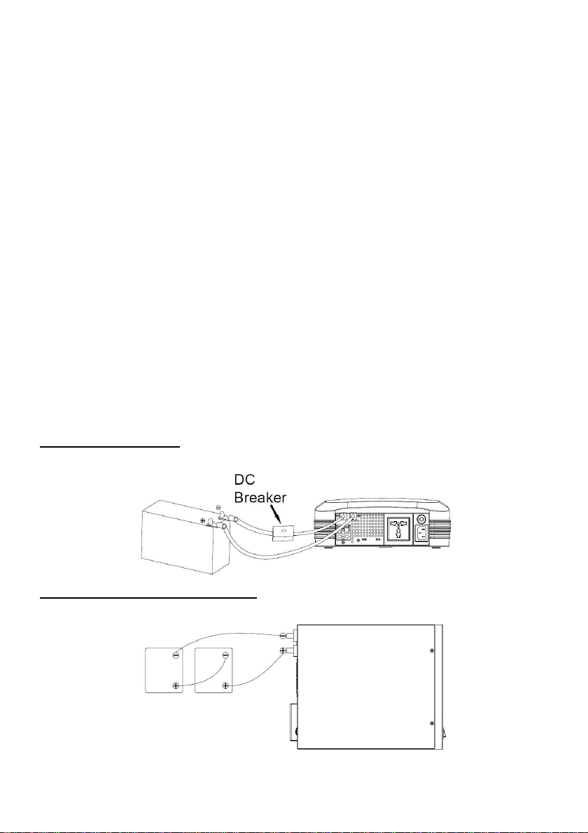
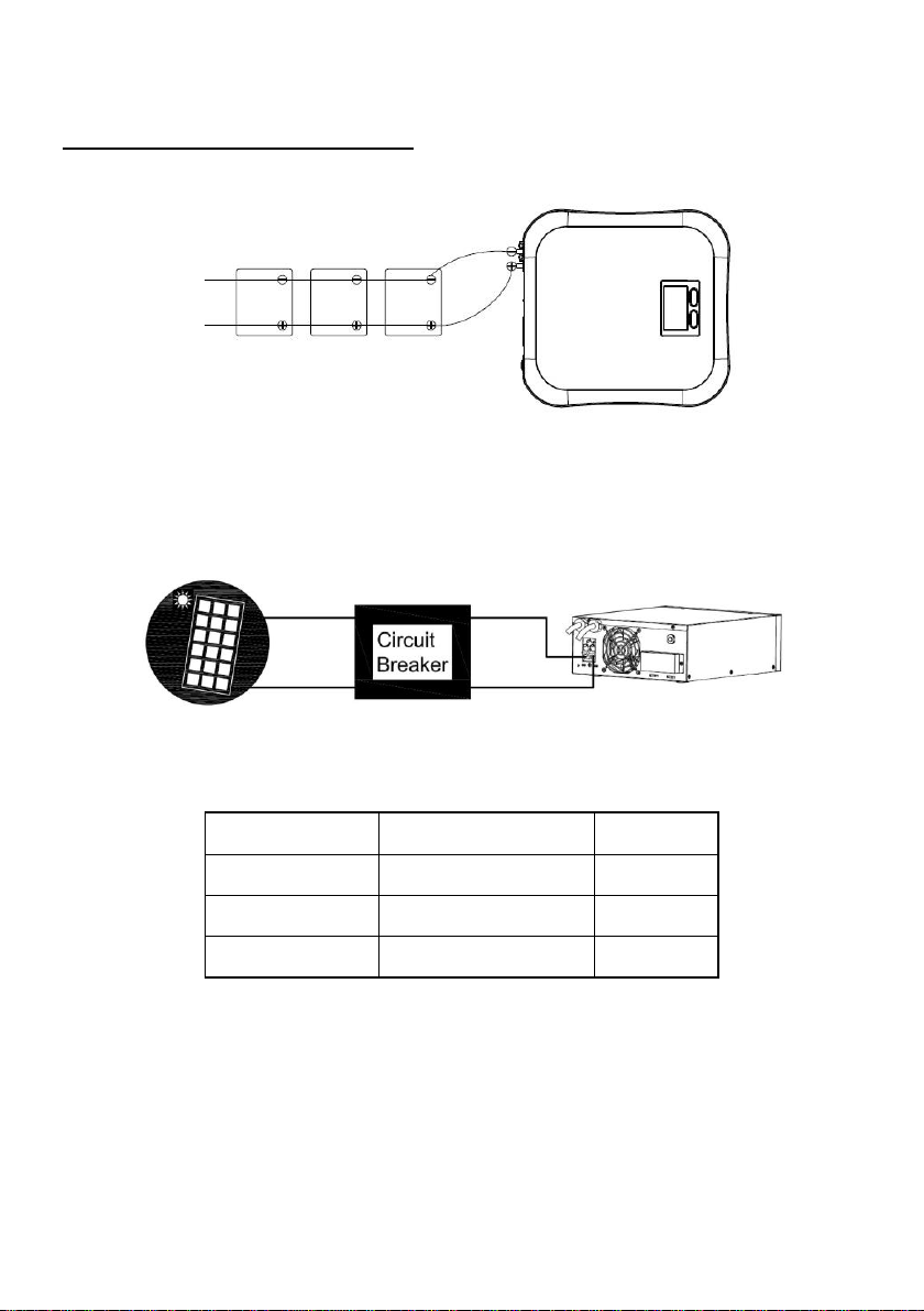
CAUTION! To reduce the risk of injury, use cables come with the product. Use appropriate and certified
external battery cables.
CAUTION! To reduce risk of damage and injury, use batteries with good quality.
CAUTION! Risk of electric shock. DO NOT remove the cover. No user serviceable parts inside.
CAUTION! Provide adequate ventilation for the battery compartment. The battery enclosure should be
designed to prevent accumulation and concentration of hydrogen gas at the top of the compartment.
CAUTION! A battery can present a risk of electrical shock and high short circuit current. When working
on batteries, remove watches, rings, or other metal objects. Use tools with insulated handles.
CAUTION! Hazardous live parts inside can be energized by the battery even when theAC input power
is disconnected.
CAUTION! To avoid electrical shock, turn off the unit and unplug it from the AC power source before
installing equipment or servicing the battery. Servicing the battery can only be performed by trained
personnel.
DO NOT USE FOR MEDICAL OR LIFE SUPPORT EQUIPMENT! Do not use in any circumstance that
would affect the operation and safety of life support equipment, medical applications, or patient care.
DO NOT USE WITH OR NEAR AQUARIUMS! To reduce the risk of fire or electric shock, do not use
with or near an aquarium. Condensation from the aquarium can cause the unit to short out.
DO NOT USE THE PRODUCT ON ANY TRANSPORTATION! To reduce the risk of fire or electric
shock, do not use the unit on any transportation such as airplanes or ships. The effect of shock or
vibration caused during transit and the damp environment can cause the unit to short out.

4
2 INSTALLATION
2-1 Unpacking
Inspect the product upon receipt. The box should contain the following:
(a) This product; (b) User Manual; (c) Input Power Cord (except for CPS3000EOH24SC)
2-2 Product Overview & Outlook
CyberPower Solar Hybrid Inverter converts renewable solar energy from panels into usableAC and
store excess power in batteries as backup power during blackout and emergencies. The Solar Hybrid
Inverter comes with a small and compact design, which helps to simplify the installation process. With
Green thinking in mind, CyberPower is always in the lead in providing the most pioneering
energy-saving solution.
CPS1200EOH12SC
CPS2200EOH24SC
User Manual
CPS3000EOH24SC
Input Power Cord
(except for CPS3000EOH24SC)

5
CPS1200EOH12SC / CPS2200EOH24SC
CPS3000EOH24SC
Application Diagram

6
2-3Power Requirements of Your Equipment
1. Ensure that the equipment plugged into the AC outlet does not exceed the product’s rated
capacity (1200VA/720W for CPS1200EOH12SC; 2200VA/1320W for CPS2200EOH24SC;
3000VA/1800W for CPS3000EOH24SC). If rated unit capacities are exceeded, an overload
condition may occur and cause the unit to shut down or the circuit breaker trip.
2. There are many factors that can affect the amount of power that your appliances will require. For
optimal system performance keep the load below 80% of the unit’s rated capacity.
2-4 Hardware Installation Guide
Step 1 Connect the Battery
For optimal battery life and reasonable recharging time, make sure the batteries capacity no less than
100Ah. Use batteries with same brand, type, and capacity.
Connect DC input cables of this product to external batteries:
Red “+”cable to the battery’s Positive “+”polarity
Black “-”cable to the battery’s Negative “-”polarity
Single Battery Connection
Single battery voltage must be equal to DC voltage of the unit.
Multiple Batteries Connection –in Series
Connect two batteries in series can double the voltage. Sum of voltages must be equal to DC voltage of
the unit.

7
Multiple Batteries Connection –in Parallel
Connect multiple batteries in parallel can increase total battery capacity but still keep terminal voltage
as single battery voltage.
Step 2 Connect the Solar Panel
CAUTION! In order to switch off the power from PV for the need of maintenance and service, please
install a circuit breaker between the product and PV module.
CAUTION! To reduce risk of injury, use appropriate cables for PV connection. The wiring can only be
performed by trained personnel. Refer to below table for recommended cable size.
Model
PV Charging Current
Wire Gauge
CPS1200EOH12SC
40A
12AWG
CPS2200EOH24SC
40A
12AWG
CPS3000EOH24SC
50A
10AWG

8
Connect the cables from PV module to the unit’s PV input terminals. Please check the polarity before
connection.
For more information about PV Module Selection, please refer to the APPENDIX section.
Step 3 Connect the Product to Utility
Connect the product to a wall outlet. Charging the battery for at least 8 hours is recommended to
ensure that the battery’s maximum charge capacity is achieved. To recharge the battery and maintain
optimal battery charge, simply leave the unit plugged into a wall outlet at all times. The battery can be
charged whether the unit is turned on or off.
DO NOT connect Neutral of the Power Distribution Box to (a) the OUTPUT Neutral of this product, or (b)
the INPUT Neutral of connected equipment. Otherwise, reversed polarity will damage the product and
connected equipment.
Step 4 Connect the Load
Connect the load to the unit’s outlet. Make sure that the total loads of your appliances are below 80% of
the unit’s rated capacity.
(請請請請請)

9
3 DEFINITIONS FOR ILLUMINATED LCD INDICATORS
LCD Display
No.
Icon
Description
1
INPUT VOLTAGE
This meter measures the AC input voltage that the unit is receiving from
the utility wall outlet. In the event of a complete power loss, severe
brownout or over-voltage, the unit will rely on its external battery to
supply consistent 230V output voltage. The Input Voltage Meter can be
used as a diagnostic tool to identify poor quality input power.
2
OUTPUT VOLTAGE
This meter measures the AC voltage that the unit is providing to the
connected device. It displays normal line mode and battery backup
mode.
3
LINE MODE
The unit is supplying utility power to connected equipment.
4
BATTERY MODE
The unit is operating from its external batteries.
5
MUTE
This icon appears whenever the unit is in silent mode. The buzzer does
not beep during silent mode until the battery reaches low capacity.
6
OVERLOAD
This icon appears and an alarm sounds to indicate the outlet is
overloaded. To relieve the overload, unplug your equipment from the
outlet until the icon disappears and the alarm stops.
7
LOAD CAPACITY
This meter displays the approximate output load level (in 25%
increments) of the unit’s outlet.
8
BATTERY CAPACITY
This meter displays the approximate charge level (in 25% increments) of
the unit’s external battery.

10
4 OPERATION & CONFIGURATION
Power On/Off
Power On:Press the POWER button to turn on the unit.
Power Off:Press the POWER button again to turn off the unit.
View LCD Information
Short press the DISPLAY button to view the information about the unit.
Display Pages
LCD Readout
Normal Mode (When the power button is pressed.)
Page 1
Output voltage. The unit is “V ”.
Page 2
Output power. The unit is “KW ”but not shown on LCD.
Page 3
Input voltage. The unit is “V ”.
Page 4
Priority of input power source.
: Solar first (default), solar energy will provide power to load as first priority.
: Utility first, utility will provide power to load as first priority.
Standby Charging Mode (When the power button is not pressed.)
Mode 1
When Utility exist
LCD only displays icon . The unit bypasses utility power to output and charge
the battery.
Mode 2
When PV exist
LCD only displays icon . Solar power charges the battery and there is no
output.
Mode 3
When both Utility
& PV exist
LCD displays icon and at the same time. The unit bypasses utility to
output. The battery is charged by both Solar and utility power.
Additional
Each Page
When PV is charging, the Solar ON icon flashes within each page.

11
Audible Alarm On/Off
Press the DISPLAY button for 2 seconds to enable the audible alarm (beep once) or disable (beep
once) the audible alarm. The MUTE icon will appear on the LCD display when the audible alarm is
disabled. The default setting is for the alarm to be in the ON position.
PV / Utility Priority
To setup the priority of input power source, press the display button for 8 seconds (beep twice) and the
priority changes from PV to Utility. The LCD will display utility first icon . If there is no action for 8
seconds, the LCD will go back to status display. The default setting is solar power first.
Charger Control
CAUTION! The setting should be performed by trained personnel. Incorrect operation will damage the
battery.
Default: The charging voltage is 13.7V for CPS1200EOH12SC and 27.4V for
CPS2200EOH24SC/CPS3000EOH24SC.
Customized (for poor battery condition): The charging voltage is 13.3V for
CPS1200EOH12SC and 26.6V for CPS2200EOH24SC/CPS3000EOH24SC. If the battery is
aging, lower the charging voltage to enhance the charging capability.
Input Voltage Range Selector
Input voltage range is defined in specification section. Output voltage is the same as input voltage inAC
mode.
Narrow (170-280Vac): For connected equipment that are sensitive to the fluctuation of voltage
range, narrow the input voltage range and the output voltage will follow.
Wide (90-280Vac): For connected equipment that are less sensitive to the fluctuation of voltage
range, set the input voltage range wider and the output voltage will follow.
Note: The transfer time will increase while the input voltage gets lower. If the connected
equipment is sensitive to the transfer time, power interruption condition may occur.

12
5 TROUBLESHOOTING
Problem
Possible Cause
Solution
The product will not turn on.
The unit is not connected to an
AC wall outlet.
The unit must be connected to a
220/230V outlet.
The battery is worn out.
Replace the batteries.
Mechanical problem.
Contact CyberPower Systems.
Outlet does not provide power to
connected equipment.
Circuit breaker has tripped
due to an overload.
Turn the unit off and remove some
of the connected equipment. Wait
10 seconds, reset the circuit
breaker by depressing the button,
and then turn the unit on.
DC fuse is blown due to
overload.
Servicing of the DC fuse should
only be performed by trained
personnel. For more information on
DC fuse replacement, contact
CyberPower Systems.
Batteries are discharged.
Recharge the unit for at least 8
hours.
The product may require
service.
Contact CyberPower Systems.
There is no LCD display.
The product is not turned on.
Press the power button.
Batteries are discharged.
Recharge the unit for at least 8
hours.
The LCD is defective.
Contact CyberPower Systems.
Utility power is normal but the
unit is in Battery Mode.
AC input is missing.
Make sure the AC input is
well-connected.
Input protector is tripped.
Reset the input protector.
The audible alarm beeps
continuously.
The unit is in Fault Mode.
Refer to Fault Code Table for
further information. Contact
CyberPower Systems.

13
Fault Code Table
Fault Code
Event
Audible Alarm
A00
Overload
Rapid beeping every 1/2 second
A05
PV Voltage High
Beep every second
A06
Battery Low
Beep every 2 seconds
A07
PV Current High
Beep every second
E50
Output Voltage High
Constant tone
E51
Output Short
Constant tone
E52
Overload Fault
Constant tone
E53
Fan Fail
Constant tone
E54
Over Charge
Constant tone

14
6 TECHNICAL SPECIFICATIONS
Model
CPS1200EOH12SC
CPS2200EOH24SC
CPS3000EOH24SC
Power Rating (VA/Watt)
1200VA/720W
2200VA/1320W
3000VA/1800W
Input
Input Voltage Range
Narrow Mode: 170 - 280Vac
Wide Mode: 90 - 280Vac
Input Frequency
50/60Hz (Auto-sensing)
Output
Output Voltage
230Vac
Output Frequency
50/60Hz
Outlet Type
(1) Universal
(1) Universal
Terminal Block
Transfer Time
< 8ms (Typical Narrow Mode)
Battery
Battery Voltage
12V
24V
24V
Charging Current
20A
10A
20A
PV Input (Solar Charger)
Maximum Input Power (Watt)
500W
1000W
1300W
Nominal PV Input Voltage
12Vdc
24Vdc
24Vdc
Optimal Operating Voltage Range
15~18VDC
30~36VDC
30~36VDC
Maximum PV Input Voltage
40V
55V
55V
Charging Current
40A
40A
50A
Environmental
Operating Temperature (°C)
0C to 40C
Operating Relative Humidity
0 to 90% (non-condensing)
Physical
Dimensions (WxHxD) (mm.)
250 x 90 x 265
250 x 90 x 265
240 x 100.5 x 280
Weight (kg.)
2.23
2.32
4.5

15
APPENDIX PV MODULE SELECTION
Find the following PV panel parameters first, and calculate to see if it meets the product’s acceptable
spec range (See Technical Specifications –PV Input section).
PV Panel Parameters
Description
Corresponding Inverter Spec
Pmax
Max. output power (W)
Max. input power (W)
Vmp
Max. power voltage (V)
Optimal operating voltage range (V)
Imp
Max. power current (A)
Charging current (A)
Voc
Open-circuit voltage (V)
Max. PV input voltage (V)
Isc
Short-circuit current (A)
Max. PV input current (A)
Please consider below requirements:
(a) Total Voc < Inverter’s max. PV input voltage
(b) Vmp falls within Inverter’s optimal operating voltage range
If one PV module cannot meet this requirement, connect multiple PV modules in series to
increase the total voltage.
Example for CPS1200EOH12SC
After considering Voc of PV module not exceeds 40VDC and Max. Vmp within 15~18VDC, we can
choose PV module with below specification.
Pmax
85W
Max. PV module numbers in series
1 →18VDC÷17.6
Vmp
17.6V
Imp
4.83A
Max. PV module numbers in parallel
9 →40A÷4.83
Total PV module numbers is 1×9=9
Voc
21.6V
Isc
5.03A
Example for CPS2200EOH24SC
After considering Voc of PV module not exceeds 55VDC and Max. Vmp within 30~36VDC, we can
choose PV module with below specification.

16
Pmax
260W
Max. PV module numbers in series
1 →36VDC÷30.9
Vmp
30.9V
Imp
8.42A
Max. PV module numbers in parallel
5 →40A÷8.42
Total PV module numbers is 1×5=5
Voc
37.7V
Isc
8.89A
Example for CPS3000EOH24SC
After considering Voc of PV module not exceeds 55VDC and Max. Vmp within 30~36VDC, we can
choose PV module with below specification.
Pmax
260W
Max. PV module numbers in series
1 →36VDC÷30.9
Vmp
30.9V
Imp
8.42A
Max. PV module numbers in parallel
6 →50A÷8.42
Total PV module numbers is 1×6=6
Voc
37.7V
Isc
8.89A
CAUTION! Ensure that Open Circuit Voltage (Voc) of PV modules not exceeds 40V for
CPS1200EOH12SC and 55V for CPS2200/3000EOH24SC, or else the inverter may be damaged.
If PV voltage or current is out of normal range, the unit will stop solar charging and send a warning
code.

17
This manual suits for next models
2
Table of contents
Other Cyber Power Inverter manuals

Cyber Power
Cyber Power CPS3000 User manual

Cyber Power
Cyber Power CPD1200EILCD User manual

Cyber Power
Cyber Power CPS1000EILCD User manual

Cyber Power
Cyber Power CPD1200EO12LCD User manual

Cyber Power
Cyber Power Mini Central CPSPV40000ETL Series User manual

Cyber Power
Cyber Power CPS5000ECH48 User manual

Cyber Power
Cyber Power CPS1200EO12LCD User manual

Cyber Power
Cyber Power CPSHB300ETR-IN User manual

Cyber Power
Cyber Power CPSPV7000ETL User manual

Cyber Power
Cyber Power Al Series User manual