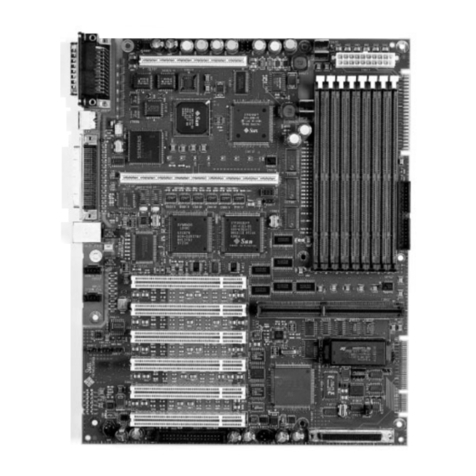
Sun Microsystems SPARCcenter 2000 User manual

SPARCcenter2000SystemBoardManual
Part No.: 800-6993-13
Revision A, October 1994
Sun Microsystems Computer Corporation
2550 Garcia Avenue
Mountain View, CA 94043
U.S.A.

Please
Recycle
1993 and 1994 Sun Microsystems, Inc.
2550 Garcia Avenue, Mountain View, California 94043-1100 U.S.A.
All rights reserved. This product and related documentation are protected by copyright and distributed under licenses
restricting its use, copying, distribution, and decompilation. No part of this product or related documentation may be
reproduced in any form by any means without prior written authorization of Sun and its licensors, if any.
Portions of this product may be derived from the UNIX®and Berkeley 4.3 BSD systems, licensed from UNIX System
Laboratories, Inc., a wholly owned subsidiary of Novell, Inc., and the University of California, respectively. Third-party font
software in this product is protected by copyright and licensed from Sun’s font suppliers.
RESTRICTED RIGHTS LEGEND: Use, duplication, or disclosure by the United States Government is subject to the restrictions
set forth in DFARS 252.227-7013 (c)(1)(ii) and FAR 52.227-19.
The product described in this manual may be protected by one or more U.S. patents, foreignpatents, or pending applications.
TRADEMARKS
Sun, the Sun logo, Sun Microsystems, Solaris, are trademarks or registered trademarks of Sun Microsystems, Inc. in the U.S.
and certain other countries. UNIX is a registered trademark in the United States and other countries, exclusively licensed
through X/Open Company, Ltd. OPEN LOOK is a registered trademark of Novell, Inc. PostScript and Display PostScript are
trademarks of Adobe Systems, Inc. All other product names mentioned herein are the trademarks of their respective owners.
All SPARC trademarks, including the SCD Compliant Logo, are trademarks or registered trademarks of SPARC International,
Inc. SPARCstation, SPARCserver, SPARCengine, SPARCstorage, SPARCware, SPARCcenter, SPARCclassic, SPARCcluster,
SPARCdesign, SPARC811, SPARCprinter, UltraSPARC, microSPARC, SPARCworks, and SPARCompiler are licensed
exclusively to Sun Microsystems, Inc. Products bearing SPARC trademarks are based upon an architecture developed by Sun
Microsystems, Inc.
The OPEN LOOK®and Sun™ Graphical User Interfaces were developed by Sun Microsystems, Inc. for its users and licensees.
Sun acknowledges the pioneering efforts of Xerox in researching and developing the concept of visual or graphical user
interfaces for the computer industry. Sun holds a non-exclusive license from Xerox to the Xerox Graphical User Interface,
which license also covers Sun’s licensees who implement OPEN LOOK GUIs and otherwise comply with Sun’s written license
agreements.
X Window System is a product of the Massachusetts Institute of Technology.
THIS PUBLICATION IS PROVIDED “AS IS” WITHOUT WARRANTY OF ANY KIND, EITHER EXPRESS OR IMPLIED,
INCLUDING, BUT NOT LIMITED TO, THE IMPLIED WARRANTIES OF MERCHANTABILITY, FITNESS FOR A
PARTICULAR PURPOSE, OR NON-INFRINGEMENT.
THIS PUBLICATION COULD INCLUDE TECHNICAL INACCURACIES OR TYPOGRAPHICAL ERRORS. CHANGES ARE
PERIODICALLY ADDED TO THE INFORMATION HEREIN; THESE CHANGES WILL BE INCORPORATED IN NEW
EDITIONS OF THE PUBLICATION. SUN MICROSYSTEMS, INC. MAY MAKE IMPROVEMENTS AND/OR CHANGES IN
THE PRODUCT(S) AND/OR THE PROGRAM(S) DESCRIBED IN THIS PUBLICATION AT ANY TIME.
iii
Contents
Preface. . . . . . . . . . . . . . . . . . . . . . . . . . . . . . . . . . . . . . . . . . . . . . . xi
1. Preparing for Installation or Service . . . . . . . . . . . . . . . . . . . . . 1-1
1.1 Required Tools . . . . . . . . . . . . . . . . . . . . . . . . . . . . . . . . . . . 1-1
1.2 Safety Precautions . . . . . . . . . . . . . . . . . . . . . . . . . . . . . . . . 1-1
1.3 System Board Description. . . . . . . . . . . . . . . . . . . . . . . . . . 1-2
1.3.1 System Master Board . . . . . . . . . . . . . . . . . . . . . . . . . 1-3
1.4 Replacement Parts . . . . . . . . . . . . . . . . . . . . . . . . . . . . . . . . 1-3
2. Removing and Replacing System Boards and Assemblies . . 2-1
2.1 Halting the System. . . . . . . . . . . . . . . . . . . . . . . . . . . . . . . . 2-1
2.2 Removing a System Board. . . . . . . . . . . . . . . . . . . . . . . . . . 2-2
2.3 Using Standoffs. . . . . . . . . . . . . . . . . . . . . . . . . . . . . . . . . . . 2-3
2.4 SuperSPARC Modules . . . . . . . . . . . . . . . . . . . . . . . . . . . . . 2-4
2.4.1 Removal . . . . . . . . . . . . . . . . . . . . . . . . . . . . . . . . . . . . 2-5
2.4.2 Installation or Replacement. . . . . . . . . . . . . . . . . . . . 2-5
2.5 SBus Cards. . . . . . . . . . . . . . . . . . . . . . . . . . . . . . . . . . . . . . . 2-6

iv SPARCcenter 2000 System Board Manual—October 1994
2.5.1 Removal . . . . . . . . . . . . . . . . . . . . . . . . . . . . . . . . . . . . 2-6
2.5.2 Replacement . . . . . . . . . . . . . . . . . . . . . . . . . . . . . . . . 2-8
2.6 SIMMs and NVSIMMs. . . . . . . . . . . . . . . . . . . . . . . . . . . . . 2-12
2.6.1 Removal . . . . . . . . . . . . . . . . . . . . . . . . . . . . . . . . . . . . 2-13
2.6.2 Installation . . . . . . . . . . . . . . . . . . . . . . . . . . . . . . . . . . 2-15
2.7 OpenBoot PROMs . . . . . . . . . . . . . . . . . . . . . . . . . . . . . . . . 2-16
2.7.1 Removal . . . . . . . . . . . . . . . . . . . . . . . . . . . . . . . . . . . . 2-17
2.7.2 Replacement . . . . . . . . . . . . . . . . . . . . . . . . . . . . . . . . 2-17
2.8 TOD/NVRAM . . . . . . . . . . . . . . . . . . . . . . . . . . . . . . . . . . . 2-18
2.8.1 Removal . . . . . . . . . . . . . . . . . . . . . . . . . . . . . . . . . . . . 2-19
2.8.2 Replacement . . . . . . . . . . . . . . . . . . . . . . . . . . . . . . . . 2-19
2.9 Installing the System Board. . . . . . . . . . . . . . . . . . . . . . . . . 2-19
2.10 Replacing the Rear Screen . . . . . . . . . . . . . . . . . . . . . . . . . . 2-20
2.11 Restarting the System. . . . . . . . . . . . . . . . . . . . . . . . . . . . . . 2-20
2.12 Selecting a System Master . . . . . . . . . . . . . . . . . . . . . . . . . . 2-21
2.12.1 When a Terminal Is Present . . . . . . . . . . . . . . . . . . . . 2-21
2.12.2 When a Terminal Is Not Present . . . . . . . . . . . . . . . . 2-22
A. Jumpers. . . . . . . . . . . . . . . . . . . . . . . . . . . . . . . . . . . . . . . . . . . . . . A-1
A.1 NVSIMM Jumpers . . . . . . . . . . . . . . . . . . . . . . . . . . . . . . . . A-1
A.2 DSBE/S Link Integrity Test Jumper . . . . . . . . . . . . . . . . . . A-2
A.2.1 FSBE/S Link Integrity Test Jumper. . . . . . . . . . . . . . A-3
A.3 System Board Jumpers. . . . . . . . . . . . . . . . . . . . . . . . . . . . . A-4
B. Connector Pinouts. . . . . . . . . . . . . . . . . . . . . . . . . . . . . . . . . . . . . B-1
B.1 Connector Locations. . . . . . . . . . . . . . . . . . . . . . . . . . . . . . . B-1

Contents v
B.2 Keyboard and Mouse Connector . . . . . . . . . . . . . . . . . . . . B-2
B.3 Serial Port Connectors . . . . . . . . . . . . . . . . . . . . . . . . . . . . . B-3
B.4 SBus Connectors. . . . . . . . . . . . . . . . . . . . . . . . . . . . . . . . . . B-4
B.5 XDBus Backplane Connectors. . . . . . . . . . . . . . . . . . . . . . . B-8
B.5.1 XDBus Connector 0. . . . . . . . . . . . . . . . . . . . . . . . . . . B-8
B.5.2 XDBus Connector 1. . . . . . . . . . . . . . . . . . . . . . . . . . . B-11
B.6 SuperSPARC Module Connectors . . . . . . . . . . . . . . . . . . . B-13
C. Environmental Specifications. . . . . . . . . . . . . . . . . . . . . . . . . . . C-1
C.1 Environmental Requirements . . . . . . . . . . . . . . . . . . . . . . . C-1
D. General Rules for System Configuration . . . . . . . . . . . . . . . . . D-1
D.1 System Master Board . . . . . . . . . . . . . . . . . . . . . . . . . . . . . . D-1
D.1.1 Identifying the System Master. . . . . . . . . . . . . . . . . . D-2
D.1.2 Minimum Requirements for the System Master . . . D-2
D.1.3 Selecting the System Master Board. . . . . . . . . . . . . . D-3
D.2 System Slave Boards. . . . . . . . . . . . . . . . . . . . . . . . . . . . . . . D-5
D.3 Selecting a SuperSPARC Module Location . . . . . . . . . . . . D-5
D.4 Selecting an SBus Module Location . . . . . . . . . . . . . . . . . . D-6
D.5 Selecting SIMM or NVSIMM Locations. . . . . . . . . . . . . . . D-8
D.6 SIMM or NVSIMM Installation Rules . . . . . . . . . . . . . . . . D-8
D.7 Identifying SIMM or NVSIMM Types . . . . . . . . . . . . . . . . D-9
D.8 Locating a Disk Drive Tray . . . . . . . . . . . . . . . . . . . . . . . . . D-10
D.9 Selecting Drive ID Numbers in the SCSI Box . . . . . . . . . . D-10
D.10 Connecting SCSI Cables. . . . . . . . . . . . . . . . . . . . . . . . . . . . D-11
D.11 Connecting DSBE/S or DWIS Cables. . . . . . . . . . . . . . . . . D-11

vi SPARCcenter 2000 System Board Manual—October 1994
D.12 Connecting Ethernet. . . . . . . . . . . . . . . . . . . . . . . . . . . . . . . D-11
D.13 Connecting Video Cables. . . . . . . . . . . . . . . . . . . . . . . . . . . D-11
Index . . . . . . . . . . . . . . . . . . . . . . . . . . . . . . . . . . . . . . . . . . . . . Index-1

vii
Figures
Figure 1-1 End and Side Views of the System Board . . . . . . . . . . . . . . . . . 1-3
Figure 1-2 Replacement Part Locations. . . . . . . . . . . . . . . . . . . . . . . . . . . . . 1-5
Figure 2-1 Rear Screen . . . . . . . . . . . . . . . . . . . . . . . . . . . . . . . . . . . . . . . . . . . 2-2
Figure 2-2 System Board Ejector/injector Levers in the Unlocked Position 2-3
Figure 2-3 Locking and Unlocking Standoffs. . . . . . . . . . . . . . . . . . . . . . . . 2-4
Figure 2-4 SuperSPARC Modules A and B. . . . . . . . . . . . . . . . . . . . . . . . . . 2-5
Figure 2-5 SBus Slot Locations . . . . . . . . . . . . . . . . . . . . . . . . . . . . . . . . . . . . 2-6
Figure 2-6 Removing or Installing an SBus Card . . . . . . . . . . . . . . . . . . . . 2-7
Figure 2-7 SBus Card Retainer . . . . . . . . . . . . . . . . . . . . . . . . . . . . . . . . . . . . 2-8
Figure 2-8 SBus Card Rear Panel with Adapter. . . . . . . . . . . . . . . . . . . . . . 2-8
Figure 2-9 DSBE/S SBus Card . . . . . . . . . . . . . . . . . . . . . . . . . . . . . . . . . . . . 2-10
Figure 2-10 FSBE/S SBus Card. . . . . . . . . . . . . . . . . . . . . . . . . . . . . . . . . . . . . 2-10
Figure 2-11 Disabling and Enabling the Link Integrity Test . . . . . . . . . . . . 2-11
Figure 2-12 SIMM Types . . . . . . . . . . . . . . . . . . . . . . . . . . . . . . . . . . . . . . . . . . 2-13
Figure 2-13 SIMM Location Numbers. . . . . . . . . . . . . . . . . . . . . . . . . . . . . . . 2-14
Figure 2-14 Unlocking a SIMM. . . . . . . . . . . . . . . . . . . . . . . . . . . . . . . . . . . . . 2-14

viii SPARCcenter 2000 System Board Manual—October 1994
Figure 2-15 Creating Space to Remove a SIMM. . . . . . . . . . . . . . . . . . . . . . . 2-15
Figure 2-16 NVSIMM Jumper Locations. . . . . . . . . . . . . . . . . . . . . . . . . . . . . 2-16
Figure 2-17 Open Boot PROM Locations . . . . . . . . . . . . . . . . . . . . . . . . . . . . 2-17
Figure 2-18 TOD/NVRAM Location. . . . . . . . . . . . . . . . . . . . . . . . . . . . . . . . 2-18
Figure A-1 NVSIMM Jumper Locations. . . . . . . . . . . . . . . . . . . . . . . . . . . . . A-1
Figure A-2 DSBE/S SBus Card Jumper . . . . . . . . . . . . . . . . . . . . . . . . . . . . . A-2
Figure A-3 FSBE/S SBus Card Jumper. . . . . . . . . . . . . . . . . . . . . . . . . . . . . . A-3
Figure A-4 Jumper Locations on the System Board . . . . . . . . . . . . . . . . . . . A-4
Figure B-1 End and Side Views of the System Board . . . . . . . . . . . . . . . . . B-2
Figure B-2 Keyboard/Mouse Connector (DIN-8) Pinout . . . . . . . . . . . . . . B-2
Figure B-3 Serial Port A and B Connector Pinouts . . . . . . . . . . . . . . . . . . . B-3
Figure B-4 Location of XDBus Connector 0 . . . . . . . . . . . . . . . . . . . . . . . . . B-8
Figure D-1 Open Boot PROM Location . . . . . . . . . . . . . . . . . . . . . . . . . . . . . D-4
Figure D-2 SuperSPARC Module Locations. . . . . . . . . . . . . . . . . . . . . . . . . D-6
Figure D-3 SBus Card Locations . . . . . . . . . . . . . . . . . . . . . . . . . . . . . . . . . . . D-7
Figure D-4 SIMM Slot Locations and U-numbers . . . . . . . . . . . . . . . . . . . . D-8
Figure D-5 SIMM Variations . . . . . . . . . . . . . . . . . . . . . . . . . . . . . . . . . . . . . . D-10

ix
Tables
Table 1-1 Safety Precautions . . . . . . . . . . . . . . . . . . . . . . . . . . . . . . . . . . . . . 1-2
Table 1-2 Replacement Part Numbers. . . . . . . . . . . . . . . . . . . . . . . . . . . . . 1-4
Table 2-1 SIMM Variations . . . . . . . . . . . . . . . . . . . . . . . . . . . . . . . . . . . . . . 2-12
Table A-1 System Board Jumpers . . . . . . . . . . . . . . . . . . . . . . . . . . . . . . . . . A-4
Table B-1 SBus Connector 0 (Connector J5700). . . . . . . . . . . . . . . . . . . . . . B-4
Table B-2 SBus Connector 1 (Connector J5701). . . . . . . . . . . . . . . . . . . . . . B-5
Table B-3 SBus Connector 2 (Connector J5702). . . . . . . . . . . . . . . . . . . . . . B-6
Table B-4 SBus Connector 3 (Connector J5703). . . . . . . . . . . . . . . . . . . . . . B-7
Table B-5 XDBus Connector 0 (Connector P0200) . . . . . . . . . . . . . . . . . . . B-8
Table B-6 XDBus Connector 1 (Connector P0300) . . . . . . . . . . . . . . . . . . . B-11
Table B-7 SuperSPARC Module Connectors (J2800 and J3100) . . . . . . . . B-13
Table C-1 Temperature Limits. . . . . . . . . . . . . . . . . . . . . . . . . . . . . . . . . . . . C-1
Table C-2 Humidity Limits . . . . . . . . . . . . . . . . . . . . . . . . . . . . . . . . . . . . . . C-2
Table C-3 Altitude Limits. . . . . . . . . . . . . . . . . . . . . . . . . . . . . . . . . . . . . . . . C-2
Table D-1 Example of Connector and Slot Priorities . . . . . . . . . . . . . . . . . D-6
Table D-2 SBus Slot Requirements for the System Master . . . . . . . . . . . . D-7

xSPARCcenter 2000 System Board Manual—October 1994
Table D-3 Example of SBus Card Distribution . . . . . . . . . . . . . . . . . . . . . . D-7
Table D-4 Example of ID Numbering in a SCSI Tray. . . . . . . . . . . . . . . . . D-11

xi
Preface
This manual is written for the trained service provider and contains service
procedures for the Sun™ SPARCcenter™ 2000 and SPARCcenter™ 2000E
system board.
When You Need Help with UNIX™ Commands
This manual does not include specific software commands or procedures. Refer
to the operating system documentation when you need help with commands
or procedures such as:
•Shutting down the system
•Booting the system
•Configuring devices
•Other software procedures
Depending on the operating system you are using, complete descriptions of
commands and procedures can be found in:
•On-line AnswerBook™ documentation that comes with Solaris
•Other software documentation you received with your system

xii SPARCcenter 2000 System Board Manual—October 1994
What Typographical Changesand Symbols Mean
Table P-1 describes the type changes and symbols used in this book.
Related Documentation
These documents contain reference information related to system board
installation and testing.
Table P-1 Typographic Conventions
Typeface or Symbol Meaning Example
AaBbCc123 The names of commands, files, and
directories; on-screen computer output Edit your .login file.
Use ls -a to list all files.
system% You have mail.
AaBbCc123 What you type, contrasted with on-screen
computer output system% su
Password:
AaBbCc123 Command-line placeholder:
replace with a real name or value To delete a file, type rm filename.
AaBbCc123 Book titles, new words or terms, or words
to be emphasized Read Chapter 6 in User’s Guide.These are called
class options. You must be root to do this.
Code samples are included in boxes and may display the following:
% UNIX C shell prompt system%
$ UNIX Bourne and Korn shell prompt system$
# Superuser prompt, all shells system#
Table P-2 Related Documents
Application Name Part Number
Safety Data Center Regulatory Compliance 801-3051
Installation Deskside/Data Center SBus Install 800-6366
Memory Module Installation Guide 801-2030
SuperSPARC Module Installation Guide 801-2035
Diagnostics SPARCcenter 2000 Post User’s Guide 800-7481
Open Boot Command Reference 800-6076

xiii
Notes, Cautions, and Warnings
Warning – The SuperSPARC module has a hot surface. Avoid contact. Surfaces
are hot and may cause personal injury if touched.
Warning – This equipment contains lethal voltage. Accidental contact can
result in serious injury or death.
Caution – Improper handling by unqualified personnel can cause serious
damage to this equipment. Unqualified personnel who tamper with this
equipment may be held liable for any resultant damage to the equipment.
Individuals who remove any outer panels or open covers to access this
equipment must observe all safety precautions and ensure compliance with
skill level requirements, certification, and all applicable local and national
laws.
Procedures contained in this document must be performed by qualified
service-trained maintenance providers.
Note – Before you begin, carefully read each of the procedures in this manual.
If you have not performed similar operations on comparable equipment, do
not attempt to perform these procedures.
User’s Guides Writing FCODE Programs for SBus Cards 800-5673
System and Network Administration for the Sun Workstation 800-1323
Service SPARCcenter 2000 Service Manual 800-2007
Table P-2 Related Documents (Continued)
Application Name Part Number
!!

xiv SPARCcenter 2000 System Board Manual—October 1994

1-1
PreparingforInstallationorService 1
This chapter discusses:
•Tools
•Safety precautions
•System boards
•Replacement parts
1.1 Required Tools •Antistatic mat
•Grounding strap
•#1 Phillips screwdriver
•IC extraction tool
1.2 Safety Precautions
Caution – When working on the system board, use an antistatic mat which has
at least 0.25" (6 mm) of cushioning. This cushioning will protect underside
components and prevent harmful board flexing.
Caution – When the system power is turned off, the AC power cord must
remain plugged in to ensure a proper ground.
Protect yourself and the equipment by observing the following precautions.
!
!

1-2 SPARCcenter 2000 System Board Manual—October 1994
1
1.3 System Board Description
Figure 1-1 identifies the major components on the system board.
Table 1-1 Safety Precautions
Item Problem Precaution
Ac power cord ESD (Electrostatic
discharge) The power cord provides a ground path for the cabinet. Do not unplug the
cord, even if the power is turned off.
Electric shock Turn the cabinet circuit breaker OFF before opening the cabinet for service.
ESD mat & wrist
or foot strap ESD Use a cushioned, antistatic mat and a grounding strap for these
procedures.
System boards ESD Handle a system board by the edges only.Store boards in antistatic bags.
Breakage Parts on a board may break if the board is flexed. Keep the board vertical
when out of the card cage. Place the board on a cushioned mat for service.
Springfingers Personal injury Springfingers have sharp edges, so handle springfinger-equipped screens
and boards carefully.
RFI leakage The screens and panels used on the cabinet suppress radio frequency
interference (RFI) and are required by law in many localities.
Damaged springfingers Replace any screen or board having broken or twisted springfingers with a
new assembly.
Cover panels System damage and
overheating Install all cover panels to keep out foreign objects and prevent overheating.
Filler panels System damage and
overheating Install filler panels in all unused card cage slots. Open slots severely
reduce the cooling capability of the system.

Preparing for Installation or Service 1-3
1
Figure 1-1 End and Side Views of the System Board
All system boards are basically the same. No jumper changes are necessary. A
board can be moved to any slot in the card cage for troubleshooting.
However, the system architecture requires that one system board serve as the
system master (being a major part of the bus arbitration system.) Also (in most
cases), the OBP master is found on the system master board.
1.3.1 System Master Board
To determine which board is system master and for a list of system master
requirements, Refer to Section D.1, “System Master Board.”
1.4 Replacement Parts
Table 1-2 lists part numbers for replacements. Replaceable parts are shown
with dotted outlines in Figure 1-2, which shows their relative locations on the
board. These items include SuperSPARC modules, SIMMs, SBus cards, the
OpenBoot PROM and the system board itself.
System error messages may specify non-replaceable components by part name,
but these components cannot be replaced in the field. If any non-replaceable
component fails, replace system board.
XDBus™
connector 1
SBus
slot 0
Diagnostic LEDs
RS232 connector A
Keyboard and
mouse connector
RS232 connector B
SBus
slot 1
SBus
slot 2
SBus
slot 3
End view Top view
0
1
2
3
BAR CODE
A
B
Super
SPARC
module
B
XDBus
connector 0
SIMM banks
0 and 1
Super
SPARC
module
A

1-4 SPARCcenter 2000 System Board Manual—October 1994
1
Table 1-2 Replacement Part Numbers
Part Part Number
SPARCcenter 2000 System board, 0 processors, 0 SIMMs 501-1866-xx
SPARCcenter 2000E System board, 0 processors, 0 SIMMs 501-2718-xx
SuperSPARC module *
OpenBoot PROM *
TOD/NVRAM 100-3528-xx
8 Mbyte SIMM (8Mx9 bits, 100ns): May be marked:MH1M72A,MH1M72BJ-8,ZA3080 (etch) or Z124SUN72 501-1817-xx
32 Mbyte SIMM (32Mx9 bits, 100ns): May be marked MH4M72J-8, Za3085 (in etch), or Z496SUN72 501-2196-xx
NVSIMM, 1Mx9 bits: The SIMM may be marked MH12872SN-70H 501-2197-xx
Filler panel, SBus slot cutout (Note: screw size is M2.5 for SBus cards) 340-2305-xx
Filler panel, card cage board slot 540-2114-xx
*-See your Sun representative for latest part number.
xx -Denotes revision level of an assembly; the factory ships the applicable revision level.

Preparing for Installation or Service 1-5
1
Figure 1-2 Replacement Part Locations
SBus 0
SBus 1
SBus 2
SBus 3
SBus
I/F
(SBI)
I/O
cache
(IOC)
I/O
cache
(IOC)
Mem.
ctrl.
(MQH)
Mem.
ctrl.
(MQH)
Bus
watcher
(BW))
BIC
&
BARB
Bus
watcher
(BW))
BIC
&
BARB
Bus
watcher
(BW))
Bus
watcher
(BW))
SIMMsSIMMs
SPARC B
module
SPARC A
module
Boot bus
EPROMUARTs
SRAM
LEDS JTAG ctrl
TODC/NVRAM
XBusXBusXBus
XDBuses
SuperSPARC
module A SuperSPARC
module B

1-6 SPARCcenter 2000 System Board Manual—October 1994
1
Other manuals for SPARCcenter 2000
2
Table of contents
Other Sun Microsystems Motherboard manuals

Sun Microsystems
Sun Microsystems SPARCengine Ultra AXi User manual

Sun Microsystems
Sun Microsystems SPARCengine Ultra AXi Manual

Sun Microsystems
Sun Microsystems F815D Series User manual

Sun Microsystems
Sun Microsystems Netra CP2500 Operating instructions

Sun Microsystems
Sun Microsystems SunSwift SPARCserver 1000 User manual