IBM M950HLU User manual

This publication, including photographs, illustrations and software,
is under the protection of international copyright laws, with all
rights reserved. Neither this manual, nor any of the material
contained herein, may be reproduced without the express written
consent of the manufacturer.
The information in this document is subject to change without
notice. The manufacturer makes no representations or warranties
with respect to the contents hereof and specifically disclaims any
implied warranties of merchantability or fitness for any particular
purpose. Further, the manufacturer reserves the right to revise this
publication and to make changes from time to time in the content
hereof without obligation of the manufacturer to notify any person
of such revision or changes.
Trademarks
IBM, VGA, and PS/2 are registered trademarks of International
Business Machines.
Intel, Pentium, Pentium-II, Pentium-III, Pentium 4, MMX,
Celeron and Tualatin are registered trademarks of Intel
Corporation.
Microsoft, MS-DOS and Windows 98/ME/NT/2000/XP are
registered trademarks of Microsoft Corporation.
PC-cillin is a trademark of Trend Micro Inc.
AMI is a trademark of American Megatrends Inc.
MediaRing Talk is a registered trademark of MediaRing Inc.
3Deep is a registered trademark of E-Color Inc.
It has been acknowledged that all mentioned brands or product
names are trademarks or registered trademarks of their respective
holders.
Copyright © 2003
All Rights Reserved
M950 Series, V3.3
P4X400/May 2003
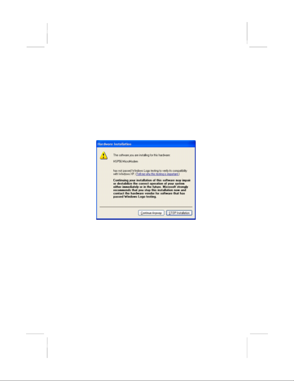
Notice:
1. Owing to Microsoft’s certifying schedule is various to every
supplier, we might have some drivers not certified yet by
Microsoft. Therefore, it might happen under Windows XP that a
dialogue box (shown as below) pop out warning you this
software has not passed Windows Logo testing to verify its
compatibility with Windows XP. Please rest assured that our RD
department has already tested and verified these drivers. Just
click the “Continue Anyway” button and go ahead the
installation.
2. USB 2.0 Driver Limitations:
2-1 The USB 2.0 driver only supports Windows XP and
Windows 2000.
2-2 If you connect a USB 2.0 hub to the root hub, plugging USB
devices into this hub, the system might not successfully
execute certain USB devices’ connection because it could
not recognize these devices.
II

Table of Contents
Chapter 1: Introduction ...................................................................1
Key Features............................................................................2
Package Contents ....................................................................5
Static Electricity Precautions...................................................6
Pre-Installation Inspection.......................................................6
Chapter 2: Mainboard Installation...................................................7
Mainboard Components ..........................................................8
I/O Ports ..................................................................................8
Installing the Processor............................................................9
Installing Memory Modules ..................................................10
Jumper Settings .....................................................................11
Install the Mainboard.............................................................12
The Panel Connector .............................................................13
Other Devices Installation .....................................................14
Expansion Slots Installation ..................................................15
Connecting Optional Devices ...............................................16
Chapter 3: BIOS Setup Utility.......................................................18
Introduction ...........................................................................18
Running the Setup Utility........... …………………………...19
Standard CMOS Setup Page..................................................20
Advanced Setup Page............................................................21
Power Management Setup Page ............................................24
PCI/Plug and Play Setup Page...............................................25
Load Optimal Settings...........................................................26
Load Best Performance Settings ...........................................26
Features Setup Page...............................................................27
CPU PnP Setup Page.............................................................28
Hardware Monitor Page ........................................................29
Change Password ..................................................................29
Exit ........................................................................................30
Chapter 4: Software & Applications .............................................31
Introduction ...........................................................................31
Installing Support Software...................................................32
Bundled Software Installation ...............................................34
Hyper Threading CPU...........................................................35
III


Chapter 1 Introduction
This mainboard has a Socket-478 supporting Intel
Pentium 4/Hyper Threading Technology processors
with front-side bus (FSB) speeds up to 533 MHz.
Hyper Threading Technology, designed to take advantage of the
multitasking features in Windows XP, gives you the power to do
more things at once.
This mainboard has the VIA P4X400 Northbridge and VT8235
Southbridge chipsets that support AC 97 audio codec, and provide
Ultra DMA 33/66/100/133 function. It supports built-in USB 2.0
providing higher bandwidth. It implements Universal Serial Bus
Specification Revision 2.0 and is compliant with UHCI 1.1 and
EHCI 0.95. This mainboard has five 32-bit PCI slots, one 8xAGP
slot, one CNR (Communications and Networking Riser) slot, and
an onboard 10BaseT/100BaseTX Network interface (optional).
This mainboard has a full set of I/O ports including two PS/2 ports
for mouse and keyboard, one serial port, one parallel port and
maximum six USB 2.0 ports– four back-panel ports and onboard
USB header USB2 providing two extra ports by connecting the
Extended USB Module to the mainboard.
This mainboard is an ATX size mainboard and has power
connectors for an ATX power supply.
Note: You must initiate the HT CPU function through
BIOS setup. It is strongly recommended you refer
to the Appendix (page 35) for relative details.

Key Features
This mainboard has these key features:
Socket 478 Processor
♦ The PGA Socket 478
♦ Supports Intel Pentium 4 series CPU with/without Hyper
Threading Technology
♦ Supports a front-side bus (FSB) of 533 MHz
Chipset
There are VIA P4X400 Northbridge and VT8235 Southbridge in
this chipset in accordance with an innovative and scalable
architecture with proven reliability and performance.
♦ Provide superior performance between the CPU, DRAM,
V-Link bus and AGP8X graphics controller bus with
pipelined, burst, and concurrent operation.
♦ Provide a 533MB/sec bandwidth Host/Client V-Link
interface with V-Link-PCI and V-Link-LPC controllers
♦ Support five PCI slots of arbitration and decoding for all
integrated functions and LPC bus.
Memory Support
♦ The mainboard accommodates two DDR 184 pin, 2.5V
DIMM sockets with a total capacity of 2 GB system
memory.
♦ Supports DDR 266/333 MHz memory bus
Built-in Graphics System
♦ AGP v3.0 compliant with 8x transfer mode compliant with
AGP 8x specification 0.9.
♦ AGP pipelined split-transaction long-burst transfers up to
1GB/sec
♦ Intelligent request reordering for maximum AGP bus
utilization
♦ Supports Flush/Fence commands
2

♦ Graphics Address Relocation Table (GART)
●One level TLB Structure
●Sixteen entry fully associative page table
●LRU replacement scheme
●Independent GART lookup control for host/AGP/PCI
master accesses
AC’97 Audio Codec
♦ Compliant with AC’97 2.1 specification
♦ 16-bit stereo full-duplex CODEC with fixed 48KHz
sampling rate
♦ 3 analog line-level stereo inputs with 5-bit volume control:
LINE-IN, CD-IN, AUX-IN
♦ 1 analog line-level mono input: PHONE-IN
♦ Three Audio Jacks – Line-Out, Line-In and Microphone-In
♦ Sound Blaster, Sound Blaster Pro Compatible
♦ Digital I/O compatible with consumer mode S/PDIF
♦ Advanced power management support
Expansion Options
The mainboard comes with the following expansion options:
♦ Five 32-bit PCI slots capable of Ultra DMA bus mastering
with transfer rates of 33/66/100/133 MB/sec
♦ One 8xAGP slot
♦ One CNR (Communications and Networking Riser) slot
Onboard I/O Ports
The mainboard has a full set of I/O ports and connectors:
♦ Two PS/2 ports for mouse and keyboard
♦ One serial port
♦ One parallel port
♦ Six USB 2.0 ports (four back-panel ports, onboard USB
header providing two extra ports)
♦ Audio jacks for microphone, line-in and line-out
3

BIOS Firmware
This mainboard uses AMI BIOS that enables users to configure
many system features including the following:
♦ Power management
♦ Wake-up alarms
♦ CPU parameters and memory timing
♦ CPU and memory timing
The firmware can also be used to set parameters for different
processor clock speeds.
USB 2.0
♦ Compliant with Universal Serial Bus Specification
Revision 2.0
♦ Compliant with Intel’s Enhanced Host Controller
Interface Specification Revision 0.95
♦ Compliant with Universal Host Controller Interface
Specification Revision 1.1
♦ PCI multi-function device consists of two UHCI Host
Controller cores for full-/low-speed signaling and one
EHCI Host Controller core for high-speed signaling
♦ Root hub consists 4 downstream facing ports with
integrated physical layer transceivers shared by UHCI and
EHCI Host Controller
♦ Support PCI-Bus Power Management Interface
Specification release 1.1
♦ Legacy support for all downstream facing ports
Built-in Ethernet LAN (Optional)
♦ 100Base-TX/10Base-T Physical Layer Solution
♦ Dual Speed – 100/10 Mbps
♦ MII Interface to Ethernet Controller/Configuration &
Status
♦ Auto Negotiation: 10/100, Full/Half Duplex
♦ Meet All Applicable IEEE802.3, 10Base-T and 100Base-
TX Standards
4

Bundled Software
♦ PC-Cillin 2002 provides automatic virus protection under
Windows 98/ME/NT/2000/XP
♦ MediaRing Talk provides PC to PC or PC to Phone
internet phone communication
♦ 3Deep delivers the precise imagery and displays accurate
color in your monitor
♦ PC DJ is a dual-MP3 player that enables users to actually
mix music right on their own personal computers.
♦ Adobe Acrobat Reader V5.0 is the software to help users
read .PDF files.
Dimensions
♦ ATX form factor of 305 x 220 mm
Note: Hardware specifications and software
items are subject to change without notification.
Package Contents
Attention: This mainboard serial has two models, M950HLU
(Hyper Threading CPU, LAN, USB2.0) and M950HU (Hyper
Threading CPU, USB 2.0).
Please contact your local supplier for more information about your
purchased model. Each model will support different specification
listed as below:
Model Specification
M950HLU Hyper Threading CPU, Onboard LAN PHY chip
(U13), USB + RJ-45 LAN connector
M950HU Hyper Threading CPU, USB connector only
Your mainboard package contains the following items:
The mainboard
The User’s Manual
One diskette drive ribbon cable (optional)
One IDE drive ribbon cable
Software support CD
5

Optional Accessories
You can purchase the following optional accessories for this
mainboard.
Extended USB module
CNR v.90 56K Fax/Modem card
Card Reader (You can buy your own Card Reader from the
third party, but please contact your local Card Reader vendor
on any issues of the specification and compatibility.)
Static Electricity Precautions
Static electricity could damage components on this mainboard.
Take the following precautions while unpacking this mainboard
and installing it in a system.
1. Don’t take this mainboard and components out of their original
static-proof package until you are ready to install them.
2. While installing, please wear a grounded wrist strap if possible.
If you don’t have a wrist strap, discharge static electricity by
touching the bare metal of the system chassis.
3. Carefully hold this mainboard by its edges. Do not touch those
components unless it is absolutely necessary. Put this
mainboard on the top of static-protection package with
component side facing up while installing.
Pre-Installation Inspection
1. Inspect this mainboard whether there are any damages to
components and connectors on the board.
2. If you suspect this mainboard has been damaged, do not
connect power to the system. Contact your mainboard vendor
about those damages.
6

Chapter 2 Mainboard Installation
To install this mainboard in a system, please follow these
instructions in this chapter:
Identify the mainboard components
Install a CPU
Install one or more system memory modules
Make sure all jumpers and switches are set correctly
Install this mainboard in a system chassis (case)
Connect any extension brackets or cables to connecting
headers on the mainboard
Install other devices and make the appropriate connections to
the mainboard connecting headers.
Note:
1. Before installing this mainboard, make sure jumper JBAT1 is
under Normal setting. See this chapter for information about
locating JBAT1 and the setting options.
2. Never connect power to the system during installation;
otherwise, it may damage the mainboard.
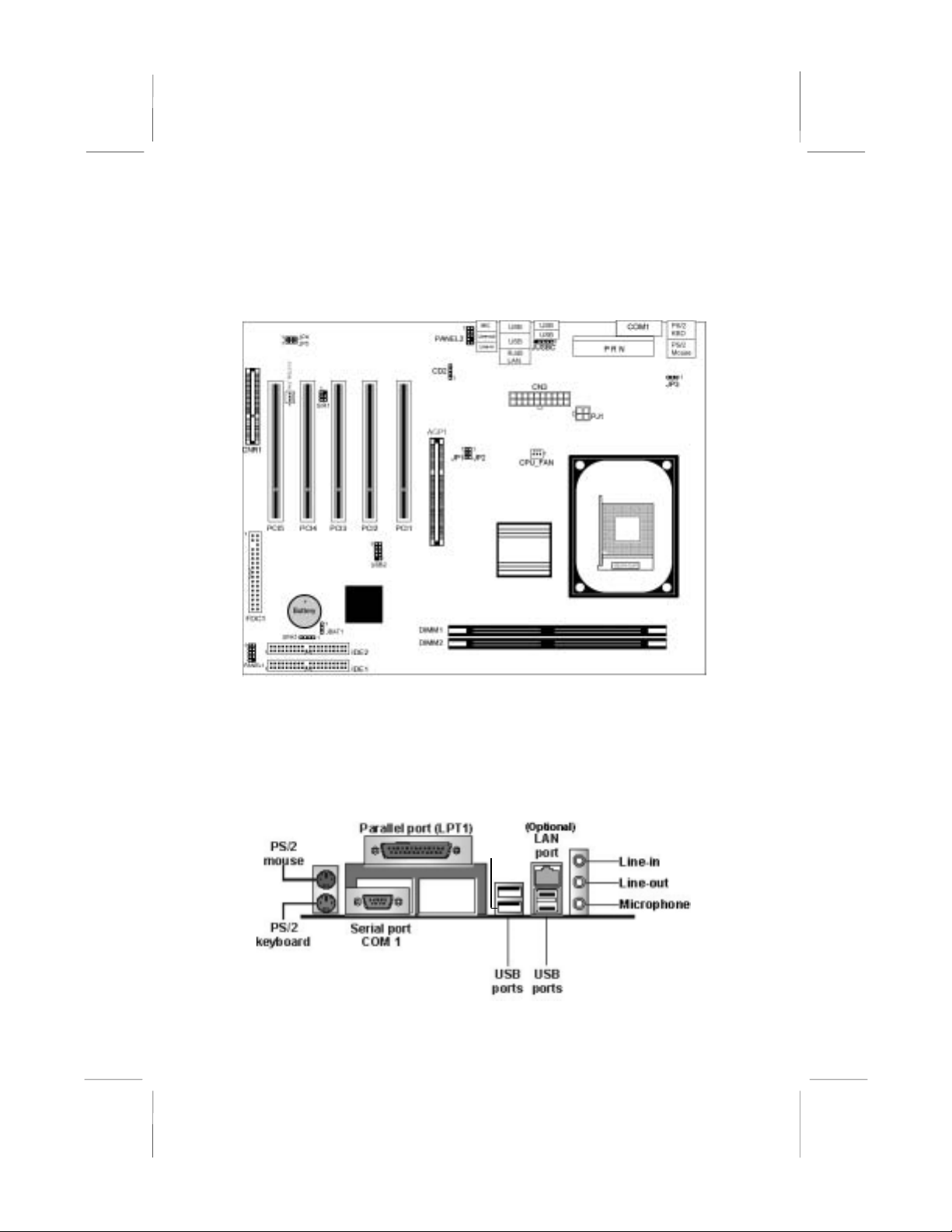
Mainboard Components
Identify major components on the mainboard via this diagram
underneath.
Note: Any jumpers on the mainboard that do not appear in
this illustration are for testing only.
I/O Ports
The illustration below shows a side view of the built-in I/O ports
on the mainboard.
(shared
with
JUSBC
)
8

PS/2 Mouse Use the upper PS/2 port to connect a PS/2
pointing device.
PS/2 Keyboard Use the lower PS/2 port to connect a PS/2
keyboard.
Parallel Port
(LPT1) Use LPT1 to connect printers or other
parallel communications devices.
COM1 Use the COM port to connect serial devices
such as mice or fax/modems. COM1 is
identified by the system as COM1.
LAN Port
(Optional) Connect an RJ-45 jack to the LAN port to
connect your computer to the Network.
USB Ports Use the USB ports to connect USB devices.
Note: The lower USB port located near the
Parallel port is shared with the JUSBC
connector.
Audio Ports Use the three audio ports to connect audio
devices. The first jack is for stereo Line-In
signal. The second jack is for stereo Line-
Out signal. The third jack is for Microphone.
Installing the Processor
This mainboard has a Socket 478 processor socket. When choosing
a processor, consider the performance requirements of the system.
Performance is based on the processor design, the clock speed and
system bus frequency of the processor, and the quantity of internal
cache memory and external cache memory.
CPU Installation Procedure
Follow these instructions to install the CPU:
1. Unhook the CPU socket’s locking lever by pulling
it away from socket and raising it to the upright
position.
2. Match the pin 1 corner of CPU socket to the one of
processor, and insert the processor into the socket.
Do not use force.
3. Push the locking lever down and hook it under the
latch on the edge of socket.
4. Apply thermal grease to the top of the CPU.
9

5. Lower the CPU fan/heatsink unit onto the CPU and
CPU socket, and then use the retention module
clamps to snap the fan/heatsink into place.
6. Plug the CPU fan power cable into the CPU
cooling fan power supply connector on the
mainboard.
Installing Memory Modules
This mainboard accommodates two 184-pin 2.5V unbuffered
Double Data Rate SDRAM (DDR SDRAM) Dual Inline Memory
Module (DIMM) sockets, and supports up to 2.0 GB
of 200/266/333 MHz DDR SDRAM.
DDR SDRAM is a type of SDRAM that supports data transfers on
both edges of each clock cycle (the rising and falling edges),
effectively doubling the memory chip’s data throughput. DDR
DIMMs can synchronously work with 100MHz, 133MHz or
166MHz memory bus.
DDR SDRAM provides 1.6 GB/s or 2.1 GB/s data transfer rate
depending on whether the bus is 100 MHz or 133 MHz.
DDR SDRAM uses additional power and ground lines and requires
184-pin 2.5V unbuffered DIMM module.
DIMM1
DIMM2
Installation Procedure
These modules can be installed with up to 2 GB system memory.
Refer to the following to install the memory module.
10

1. Push the latches on each side of the DIMM socket
down.
2. Align the memory module with the socket. The
DIMM sockets are keyed with notches and the
DIMMs are keyed with cutouts so that they can
only be installed correctly.
3. Check that the cutouts on the DIMM module edge
connector match the notches in the DIMM socket.
4. Install the DIMM module into the socket and press
it firmly down until it is seated correctly. The
socket latches are levered upwards and latch on to
the edges of the DIMM.
5. Install any remaining DIMM modules.
Jumper Settings
JP4 JP3
JP5
1
1
1
JP2
11
JP1
1
JBAT1
JBAT1: Clear CMOS Jumper
This jumper is to clear the contents of CMOS memory. You may
need to clear the CMOS memory if the settings in the Setup Utility
are incorrect that prevents your mainboard from operating. To clear
the CMOS memory, disconnect all the power cables from the
mainboard and then move the jumper cap into the CLEAR setting
for a few seconds.
Function Jumper Setting
Normal Short Pins 1-2
Clear CMOS Short Pins 2-3
11

JP1, JP2: CPU Clock Selector
This jumper enables to select CPU frequency.
CPU Clock JP1 JP2
100M Short Pins 1-2 Short Pins 2-3
133M Short Pins 2-3 Short Pins 1-2
JP3: Keyboard Power On/Off
If the Keyboard Power On is enabled, hot keys on the keyboard
can work as a power on/off switch for the system.
Function Jumper Setting
Disabled Short Pins 1-2
Enabled Short Pins 2-3
Note: The system must supply at least 1A on the +5VSB (+5V
Standby) signal before enabling the Keyboard Power On function.
JP4: Flash ROM Size Selector
This jumper enables to select size of flash ROM.
Function Jumper Setting
2M Short Pins 1-2
4M Short Pins 2-3
JP5: Flash ROM Voltage (VCC) Selector
This jumper enables to select voltage of flash ROM.
Function Jumper Setting
5V Short Pins 1-2
3V Short Pins 2-3
Install the Mainboard
Install the mainboard in a system chassis (case). The board is an
ATX size mainboard. You can install this mainboard in an ATX
case. Make sure your case has an I/O cover plate matching the
ports on this mainboard.
Install the mainboard in a case. Follow the case manufacturer’s
instructions to use the hardware and internal mounting points on
the chassis.
12

PJ1
1
SYSTEM_FAN
PANEL1
PANEL2
1
CN3
1
Connect power supply to the CN3 connector on the mainboard.
PJ1 is the CPU Vcore power connector.
If there is a cooling fan in the system chassis, connect the cooling
fan cable to the SYSTEM_FAN fan power connector on the
mainboard.
The Panel Connector
PANEL1
This panel connector provides a set of switch and LED connectors
found on ATX case. Refer to the table below for information.
Device Pins
Empty 10
N/C 9
Power
ON/OFF 6, 8
Reset Switch 5, 7
SPD-LED
Indicator +2, 4
HDD LED +1, -3
HDD LED
(Pins 1, 3)
2 1
Reset Switc
h
(Pins 5, 7)
Power Switch
(Pins 6, 8)
SPD-LED
(Pins 2, 4)
Empty
(Pin 10)
10 9
N/C
(Pin 9)
+ +
13

PANEL2
If there are a headphone jack or/and a microphone jack on the front
panel, connect the cables to the PANEL2 on the mainboard.
Device Pins
Line Out (L) 9, 10
Empty 8
NC 7
Line Out (R) 5, 6
+5V Audio 4
VCCMIC 3
GND 2
MIC IN 1
MIC IN
(Pin 1)
2 1
Line Out(R)
(Pin 5)
10 9
Line Out(L)
(Pin 9)
GND
(Pin 2)
VCC MIC
(Pin 3)
+5V Audio
(Pin 4)
Line Out(R)
(Pin 6)
NC (Pin 7)
Empty
(Pin 8)
Line Out(L)
(Pin 10)
Other Devices Installation
Floppy Diskette Drive Installation
The mainboard has a floppy diskette drive (FDD) interface and
ships with a diskette drive ribbon cable that supports one or two
floppy diskette drives. You can install a 5.25-inch drive and a 3.5-
inch drive with various capacities. The floppy diskette drive cable
has one type of connector for a 5.25-inch drive and another type of
connector for a 3.5-inch drive.
IDE Devices
Your mainboard has a primary and secondary IDE channel
interface (IDE1 and IDE2). An IDE ribbon cable supporting two
IDE devices is bundled with the mainboard.
If you want to install more than two IDE devices, get a second IDE
cable and you can add two more devices to the secondary IDE
channel.
IDE devices have jumpers or switches to set the IDE device as
MASTER or SLAVE. When installing two IDE devices on one
cable, ensure that one device is set to MASTER and the other one
to SLAVE.
14

This mainboard supports Ultra DMA 66/100/133. UDMA is a
technology to accelerate devices’ performance in the IDE channel.
To maximize performance, install IDE devices that support UDMA
and use 80-pin IDE cables supporting UDMA 66/100/133.
Expansion Slots Installation
This mainboard has one 8xAGP, one CNR and five 32-bit PCI
(Peripheral Components Interconnect) expansion slots.
8 x AGP (Accelerated Graphics Port) Slot
You can install a graphics adapter supporting 8xAGP specification
in the AGP slot. This slot has one 8xAGP edge connector.
CNR (Communications Networking Riser) Slot
You can install a CNR (the Communications Networking Riser)
card in the CNR slot.
PCI (Peripheral Components Interconnect) Slot
You can install the 32-bit PCI interface expansion cards in the slots.
PCI 4 PCI2
AGP1
CNR1
PCI 5 PCI3 PCI1
1. Remove a blanking plate from the system case
corresponding to the slot you are going to use.
2. Install the edge connector of the expansion card
into the expansion slot. Ensure that the edge
connector is correctly seated in the slot.
3. Secure the metal bracket of the card to the system
case with a screw.
15

Connecting Optional Devices
Refer to the following for information on connecting the
mainboard’s optional devices:
1
USB2
1
SIR1
1
1
SPK1
CD2
1
JUSB
C
SPK1: Speaker Connector
Connect the cable from the PC speaker to the SPK1 header on the
mainboard.
Pin Signal Pin Signal
1 SPKR 2 NC
3 GND 4 +5V
USB2: Front panel USB header
The mainboard has USB ports installed on the rear edge I/O port
array. Some computer cases have a special module that mounts
USB ports at the front of the case. If you have this kind of case, use
auxiliary USB connectors USB2 to connect the front-mounted
ports to the mainboard.
Pin Signal Pin Signal
1 VERG_FP_USBPWR0 2 VERG_FP_USBPWR0
3 USB_FP_P0- 4 USB_FP_P1-
5 USB_FP_P0+ 6 USB_FP_P1+
7 GROUND 8 GROUND
9 KEY 10 USB_FP_OC0
JUSBC: USB Card Reader Connector (optional)
This connector is for connecting internal USB card reader. You can
use a card reader to read or transfer files and digital images to your
computer.
16
This manual suits for next models
1
Table of contents
Other IBM Motherboard manuals


Popular Motherboard manuals by other brands


 user manual")


Microchip Technology
Microchip Technology PIC18F47Q10 Curiosity Nano Hardware user's guide

Intel
Intel DH67BL quick reference

Gigabyte
Gigabyte GA-Z87-D3H user manual

SOYO
SOYO SY-7VCA-E quick start guide

Sapphire Audio
Sapphire Audio PURE CROSSFIRE II PC-I7RD400 user manual

Gigabyte
Gigabyte GA-H170-Designare user manual


